Alicat Scientific M Series User manual

The Fastest Flow Controller Company in the World!
OPERATING MANUAL
M · MW · MS · MQ · MB

2 IntroductIon
Thank you for purchasing an Alicat flow meter.
If you have any questions about operating it, or if
something is not working as expected, please let us know.
We are eager to help you in any way possible.
Alicat Scientific, Inc.
info@alicat.com • alicat.com
7641 N Business Park Drive, Tucson, AZ 85743 USA
1-888-290-6060
Serial Number:
Next Calibration (Month/Day) :
Recalibrate your flow meter every year.
Alicat recommends that you have your flow meter calibrated every year
in order to ensure the continued certainty of your readings and extend
the Limited Lifetime Warranty. When it’s time for your flow meter’s annual
recalibration, contact us by phone, email or live chat to set it up, or fill out
the Service Request Form at alicat.com/service.
This Alicat device comes with a NIST traceable
calibration certificate.
This Alicat flow meter conforms to the European
Union’s Restriction of Use of Hazardous Substances
in Electrical and Electronic Equipment (RoHS)
Directive 2011/65/EU.
This Alicat flow meter complies with the
requirements of the Low Voltage Directive
2014/35/EU and the EMC Directive 2014/30/EU and
carries the CE Marking accordingly.
This Alicat flow meter complies with the
requirements of the European Union’s Waste
Electrical & Electronic Equipment (WEEE) Directive
2002/96/EC.
DOC-MANUAL-M Rev , 2020.02.20

2020.02.20 REV. 3
Welcome to the
Alicat way.
You're busy, and the last thing you want to do is waste time wrestling with
your flow meter. We're here to make your life a little easier so you can do
what you do best. It's our pleasure to introduce you to your new Alicat:
• High-accuracy performance for all your gases. Use
your flow meter with any of the 98 or more gases
that are part of Gas Select™, page 23.
• 1000 readings per second ensures high resolution data, page 29.
• Monitor pressure and temperature during flow measurement. View
internal stream absolute pressure and temperature, page 17.
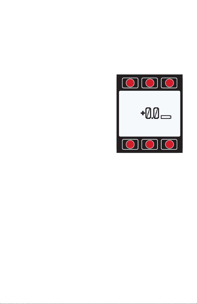
• Backlit display with adjustable contrast is easy to
read in direct sunlight. In dimly lit areas, press the
Alicat logo to turn on the backlight, page 7.
• Change your STP to match any standard temperature
and pressure reference, page 27.
• Log data to your PC. Talk to the flow meter serially to capture
all flow data for logging and analysis, page 31.
This manual covers the following Alicat Scientific instruments:
• M-Series Mass Flow Meters
• MQ-Series High-Pressure Mass Flow Meters
• MS-Series Mass Flow Meters for use with Aggressive Gases
• MW (WHISPER) Low Pressure Drop Mass Flow Meters
• MB-Series Portable Mass Flow Meters
• MBS-Series Portable Mass Flow Meters for Aggressive Gases
• MQB-Series Portable High-Pressure Mass Flow Meters
• MWB (WHISPER) Portable Low Pressure Drop Mass Flow Meters
This includes M-Series devices labeled as approved for CSA Class 1 Div
2 and ATEX Class 1 Zone 2 hazardous environments. See page 50 for
Special Conditions regarding the use of CSA/ATEX labeled devices.
Please contact Alicat at 1-888-290-6060 or info@alicat.com if you have
any questions regarding the use or operation of this device.

4 taBle of contentS
Contents
Quick Start Guide
Getting Started
Getting to Know Your Mass Flow Meter
Connectors and Buttons
The Flow Meter Display
Status Messages
Option: Charging Your Portable Flow Meter
Mounting
Filters
Connecting Your Gas Flow Meter
Power and Signal Connections
RS-232 / RS-485 Digital Input / Output Signal
Analog Signals
Option: Color TFT Display
Navigation and Customization
Flow Meter Menu Map
Collecting Live Flow Data
Choosing Engineering Units
Option: Collecting Totalized Flow Data
Menu
Taring Your Flow Meter
About
Diagnostic Information
Basic Configuration Menu
Choosing Engineering Units from the Basic Configuration Menu
Gas Select™
Gas List
Using COMPOSER™ to Personalize Mixed Gas Compositions
Adding a new mixed gas composition to COMPOSER™
Defining STP/NTP Reference Values
Advanced Setup
Display Setup
Sensor Setup
Configuring Serial Communications

2020.02.20 REV. 5
Serial Communication
Establishing Communication
Streaming vs Polling
Polling Mode
Streaming Mode
Taring
Collecting Flow Data
Quick Command Guide
Using Gas Select™and COMPOSER™
Troubleshooting
Maintenance
Gas List
Engineering Units
Flow Units
Pressure Units
Optional Pinouts
Locking Industrial Connector Pinouts
9-pin D-Sub Common Pinouts
M12 Connector Pinouts
15-pin D-Sub Common Pinouts

6 QuIck Start
Quick Start Guide
Setup
•
Connect your flow meter. Ensure that flow through your device will be
in the same direction as the arrow on the flow body (usually left to right).
•
Tare your flow meter. Before you connect the flow meter, ensure
that no air is flowing through the device and select TARE FLOW from
the Main Display. Note: Whisper flow meters are sensitive enough to
measure the lightest of breezes, so ensure that one end is plugged
before selecting tare.
•
Choose your engineering units. Press the button above or below
any parameter to enlarge it in the middle of the display. If you select
that same item a second time, you can change the engineering unit for
that parameter. You can choose units for all of the parameters at once
by selecting MENU →BASIC CONFIG →DEVICE UNITS.
Operation: Flow Verification
•
Monitor live flow readings. You can monitor live readings of flow,
pressure and temperature by viewing the screen. Readings are updated
in real time. See page 17.
•
Tare your flow meter before you begin another round of measurements.
Ensure that no flow is passing through your meter, and select
TARE
FLOW. See page 20.
•
(Optional) Capture a totalized reading. The totalizer option displays
the total flow that has passed through the device since the last time
the totalizer was reset. Press TOTAL/MENU to access the totalizer.
Backlight
Your Alicat monochrome display comes equipped with a backlight. To
activate, press the center of the Alicat logo on the front of your
device. To turn the backlight o press the button again. For color displays,
pressing this button will turn o the display to conserve power.
Maintenance and Care
• If your gas is clean, your flow meter will require no periodic cleaning.
Read more on page 40.
•
Calibrate your flow meter annually. Request an Alicat factory calibration
at alicat.com/service or by calling Alicat at 1-888-290-6060.

2020.02.20 REV. 7
Getting Started
Getting to Know Your Mass Flow Meter
Connectors and Buttons
The drawings below represent typical configurations of a standard Alicat
mass flow meter (M series) and a standard battery-powered mass flow
meter (MB series). Your flow meter's appearance and connections
may differ.
+0.0 +0.0
+13.49 +22.73
Mass Flow
CCM SCCM MENU
PSIA ¤C TARE
FLOW
SCCM
A ir
+0.0 +0.0
+13.49 +22.73
Mass Flow
CCM SCCM MENU
PSIA ¤C TARE
FLOW
SCCM
A ir
Process ports
Mounting holes
Flow body
Light button
Display
Softkey buttons
Power input Data I/O
Micro-USB
(data & power)
Power switch
Enclosed
battery
Meters
(M-Series) Battery-Powered Meters
(MB-Series)

8 GettInG Started
The Flow Meter Display
The figure below identifies the various features of the flow meter display.
Press the large button with the Alicat logo to toggle the backlight on and
o. For more details, see the Menu Map on page 16 and the menu-
by-menu descriptions that follow it.
Engineering units are used by the meter in its serial communications and
calculations. These can be dierent from button units, which are the units
being displayed. These are individually configurable. See page 18.
Highlights pressure in the center
of the meter. Push a second
time to choose the pressure
parameter (if available), or to select
pressure engineering units.
Highlights temperature.
Push a second time to select
temperature engineering units.
TARE FLOW tare the flow
rate (see page 20).
Highlights volumetric (actual)
flow rate. Push a second
time to select volumetric flow rate engineering units.
Highlights mass flow rate. Push a second time to select mass
flow (normal mass flow) or true mass flow engineering units.
TOTAL/MENU Accesses the optional flow totalizer (optional)
(page 19). MENU enters the Menu system (page 16)
Status Messages
ADC Analog-digital
converter error
LCK Front display is locked
OVR Totalizer rolled over to zero
POV Pressure over
range of device
MOV Mass flow over
range of device
TMF Totalizer missed out
of range flow
TOV Temperature over
range of device
VOV Volumetric flow over
range of device
+0.0 +0.0 TOTAL/
+13.49 +22.73
Mass Flow
LPM SLPM MENU
PSIA ¤C TARE
FLOW
SLPM
A ir
1 2 3
4 5 6

2020.02.20 REV. 9
Option: Charging Your Portable Flow Meter
If you purchased a portable meter, we've fully charged it at the factory, so
you can use it right away. Typical battery life of a fully-charged battery is 18
hours with a monochrome display or 8 hours with a TFT color display, when
the backlight is set to 10. Dimming the backlight will increase battery life.
The battery indicator on the right side of the Main Display reflects the relative
battery level. When the battery indicator is completely empty, approximately
15 minutes of battery life remains. Please charge the flow meter as soon as
possible to maintain full device performance.
Charge the flow meter using the supplied USB cable (micro-B to type A) or
a similar cable. You may charge the flow meter using any USB outlet on a
computer or portable power supply, but charging will be fastest (approx-
imately 3.5 hours) when connected to the supplied 2.0A power supply.
The red indicator LED on top of the device lights up red to indicate that the
unit is charging. The red LED turns o when the battery is charged.
Your flow meter may be used while it is charging. A small lightning bolt
symbol ( ) will appear to the right of the battery symbol while the device
is charging. If the battery has been fully depleted, you may need to charge
the flow meter for a full minute before the device can be turned on.
! Warning: The safe charging temperature range is
0-45 °C (32-113 °F). If internal sensors detect temperatures
outside of this range, the battery will not charge.
LPM
Air
Vol Flow
+16.67
MENU
+15.44
SLPM
+16.67
LPM
TARE V
#C
+24.38
PSIA
+13.60
95 – 100%
70 – 95%
50 – 70%
25 – 50%
5 – 25%
0 – 5%
Charging Indicator

10 GettInG Started
Mounting
No straight runs of pipe are required upstream or downstream of the
meter. For most Alicat flow meters, you can mount or hold the meter in
any position, because it is internally compensated for any changes to its
orientation during use. (MS/MBS series flow meters use media-isolated
sensors that must be tared after changing orientation.) Your flow meter is
also minimally aected by vibrations, so you can rest it on top of a vibrating
instrument with little impact to measurement accuracy.
Device Ports
Your flow meter has been shipped with plastic plugs fitted into its ports.
To lessen the chance of contaminating the flow stream, do not remove
these plugs until you are ready to install the device.
Standard Alicat Gas Flow Meters have female inlet and outlet ports.
Welded VCR and other specialty fittings may have male connections.
• If you are using a fitting that does not have a face seal, use
thread-sealing Teflon tape to prevent leakage around the
port threads, but do not wrap the first two threads. This
will minimize the possibility of getting tape into the flow
stream and clogging the laminar flow elements (LFE).
• If you are using a fitting that has a face seal, there is
no need to apply Teflon tape to the threads.
! Warning: Do not use pipe dopes or sealants on the process
connections, as these compounds can cause permanent
damage to the meter should they get into the flow stream.
Filters
When pressure drop is not an issue, use in-line sintered filters to prevent
large particulates from entering the flow meter. Suggested maximum
particulate sizes are as follows:
• 5 microns for units with flow ranges of 1 or less.
• 20 microns for units with flow ranges between 2 and 1 .
• 50 microns for units with flow ranges of 1 or more.

2020.02.20 REV. 11
Connecting Your Gas Flow Meter
Your Alicat flow meter can measure flow generated by positive pressure
and/or suction. Connect the meter so that the flow travels in the same
direction as the flow arrow, usually from left to right as you look at the
front of the device.
Inlet
Connection
Outlet
Connection
Flow Direction Indicator
Model
Max Common
Mode Pressure
Max Dierential
Pressure
M, MS, MB, MBS 175 75
MW, MWB 80 10
MQ, MQB 400 75

12 GettInG Started
Power and Signal Connections
Power can be supplied to your meter through either the power jack or the
multi-pin connector on top of your device.
✓ Meter power jacks require a 9–24 Vdc power supply with a 2.1
mm female positive center plug capable of supplying at least
50 mA. 4–20 mA analog signal outputs require at least 12 Vdc
and 100 mA, and 0–10 Vdc outputs require at least 12 Vdc.
Standard 8-Pin Mini-DIN Pinout
Pin Function Cable color
Not Connected
(or optional 4–20 mA Primary Output Signal) Black
Static 5.12 Vdc (or optional Secondary Analog Output
[4–20 mA, 0–5 Vdc, 1–5V dc, 0–10 Vdc] or Basic Alarm) Brown
Serial RS-232RX / RS-485(–) Input Signal (receive) Red
Remote Tare (Ground to Tare) Orange
Serial RS-232TX / RS-485(+) Output Signal (send) Yellow
0–5 Vdc (or optional 1–5 Vdc or 0–10 Vdc) Output Signal Green
Power In (as described above) Blue
Ground (common for power, digital communications,
analog signals and alarms) Purple
Note: The above pinout is applicable to all flow meters with the Mini-DIN
connector. The availability of dierent output signals depends on the options
ordered. Optional configurations are noted on the unit’s calibration sheet.
Caution: Do not connect power to pins 1 through 6, as permanent
damage can occur. It is common to mistake Pin 2 (labeled 5.12 Vdc
Output) as the standard 0–5 Vdc analog output signal. Pin 2 is
normally a constant 5.12 Vdc that reflects the system bus voltage.
For 6-pin locking industrial connector, M12, DB9 and DB15 pinouts,
see page 45 to page 48 or visit alicat.com/pinout.
12
5
3
4
678
21
3
5
4
876
Male Connector: CableFemale Connector: Device

2020.02.20 REV. 13
RS-232 / RS-485 Digital Input / Output Signal
To use the RS-232 or RS-485 digital signal, connect the RS-232 / RS-485
Output Signal (Pin 5), the RS-232 / RS-485 Input Signal (Pin 3) and Ground
(Pin 8) to your serial port as shown below. (See "Serial Communications"
on page 31 for details)
DB9 to 8-Pin Mini-DIN Connection for RS-232 / RS-485 Signals
9 Pin Serial Connection 8 Pin Mini-DIN Connection
Pin Function Pin Function
5Ground 8Ground
3Transmit 3Receive
2Receive 5Transmit
DB9 connections
Male Connector: Cable Female Connector: Device
1
69
55
96
1

14 GettInG Started
Analog Signals
Primary Analog Output Signal
Most Alicat instruments include a primary analog output signal, which is linear
over its entire range. For both standard 0–5 Vdc and optional 0–10 Vdc
output signals, a zero flow condition is usually in the range of 0.010 Vdc.
Zero flow for the optional 1–5 Vdc and 4–20 mA output signals is 1 Vdc and
4 mA, respectively. Full-scale flow is 5 Vdc for 0–5 Vdc and 1–5 Vdc signals,
10 Vdc for 0–10 Vdc signals and 20 mA for 4–20 mA signals.
Alicat’s default 8-pin mini-DIN connector places the primary analog output
on Pin 6 for voltage signals and Pin 1 for 4–20 mA current signals. Ground
for these signals is common on Pin 8.
Using Ground to Tare
You can tare your mass flow meter remotely by momentarily grounding
Pin 4, as shown below. When the switch is closed, the device will tare,
and resume operation once the switch has been released.
Option: Second Analog Output Signal
Alicat’s default 8-pin mini-DIN connector places the secondary analog
output on Pin 2 for both voltage and current signals. Your device’s
secondary analog signal may dier from its primary output signal.
✓ See the calibration sheet that shipped with your meter
to determine which output signals were ordered.
Option: 4–20 mA Current Output Signal
If your meter has a 4–20 mA current primary or secondary output signal,
your flow meter will require 12–24 Vdc power.
Caution: Do not connect 4–20 mA devices to “loop powered’”
systems, as this will destroy portions of the circuitry and void the
warranty. If you must interface with existing loop powered systems,
always use a signal isolator and a separate power supply.
Pin 8
Ground
Pin 4
Connect to tare

2020.02.20 REV. 15
Option: Color TFT Display
Instruments ordered with a color display function the same as standard
backlit monochrome instruments, but color is used to provide additional
on-screen information.
Multi-Color Display Indicators
• GREEN: Parameter labels and adjustments associated with the
button directly above or below the label are presented in green.
• WHITE: The color of each parameter is displayed in
white while operating under normal conditions.
• RED: The color of a parameter is displayed in red when
its value exceeds 128% of the device’s specifications.
• YELLOW: Menu items that are ready to be selected
appear in yellow. This color replaces the symbol
(>) in selections on monochrome display.
✓ Press the Alicat logo button to turn o the color
display backlight. The flow meter remains in
operation while the backlight is o.
LCD Contrast
LCD contrast is ranged from 0 to 11 on color displays, with 11 indicating
the greatest contrast. See “Display Setup” on page 28.
Specifications for Instruments with Color Displays
Color displays will require an additional 40 mA when using a 24 Vdc
power supply. All other specifications from your device’s specification
sheet remain in eect.
Specification Meter
Supply Voltage 7–24 Vdc
Supply Current 80 mA at 12 Vdc
70 mA at 24 Vdc

16 navIGatIon and cuStoMIzatIon
Navigation and
Customization
Flow Meter
Menu Map
M PEAK
+18.03
MENU/
MAIN
SLPM
+15.44
TOTAL/
TIMER
RESET
2:56 h:m:s
+45.29
M AVG +15.44 SL
SLPM
Air
Mass Flow
+15.44
TOTAL/
MENU
+15.44
SLPM
+16.67
LPM
TARE
FLOW
#C
+24.38
PSIA
+13.60
Main Display
*
Optional
Flow
Totalizer
Basic Config
(page 22)
MAIN
BACK
STP/
NTP
DEVICE
UNITS
GAS
Air
Adv Setup
(page 28)
MAIN
BACK
DISP
SETUP
COMM
SETUP
SENSOR
SETUP
About
(page 21)
MAIN
BACK
MFG
INFO
DEVICE
STATE
DEVICE
INFO
Main Menu
(page 20)
MAIN
ADV
SETUP
BASIC
CONFIG
TARESABOUT
Tares
(page 20)
MAIN
BACK
TARE
FLOW
TARE
PRESS
*
*
*
*
*
*Press MAIN to return
to the Main Display.
Start Here
Without
Flow
Totalizer

2020.02.20 REV. 17
Collecting Live Flow Data
The Main Display has two primary functions:
• Collecting live temperature, pressure and flow data (see below)
• Changing engineering units for temperature,
pressure and flow (page 18)
This screen displays live data for all flow parameters simultaneously. Live
data is measured 1000 times per second and typically displayed 10 times
per second on the device LCD screen. Press the button next to any of the
four flow parameters once to highlight its value in the center of the screen.
Press the same button again to enter the engineering unit selection menu
for that parameter (page 18).
Main Display
Highlights pressure in the center
of the meter. Push a second
time to select engineering units
or the pressure parameter:
•Internal absolute pressure
•Internal gauge pressure (optional)
•Barometric pressure (optional)
Highlights temperature.
Push a second time to select
temperature engineering units.
TARE FLOW Tares the flow rate (see page 20).
Highlights volumetric (actual) flow rate. Push a second
time to select volumetric flow rate engineering units.
Highlights mass flow rate. Push a second time to select
mass flow engineering units and switch between
standardized, normalized, and true mass flow.
TOTAL Accesses flow totalizer (optional) (page 19).
MENU enters the Menu system (page 20).
+0.0 +0.0
+13.49 +22.73
Mass Flow
LPM SLPM MENU
PSIA ¤C TARE
FLOW
SLPM
A ir
LCK
1 2 3
4 5 6

18 navIGatIon and cuStoMIzatIon
Choosing Engineering Units
Press the button adjacent to any of the four
measurement parameters twice to enter its
unit selection menu. You can change units in
two ways:
Button engineering units (page 18) alter
the display only, not the serial data:
• Select Set button eng units and
press SELECT to change the engineering
unit on the display only. This does
not alter the flow meter data frame.
Device engineering units alter both the
display and the flow meter data frame:
• Select Set device eng units and then
choose the engineering unit as above.
An additional confirmation screen asks
you to confirm the serial change.
If the button engineering unit is dierent than
the device engineering unit, Set device eng
units will not appear. First select Show device
eng units to revert the button to the current
device unit for that parameter. Enter the unit
selection menu again to change the device
engineering unit.
Examples of changing device engineering units:
SETCANCEL
PRESSING SET WILL
AFFECT DISPLAY
AND SERIAL VALUES.
VERIFY CONNECTED
SERIAL DEVICES
EXPECT THE CHANGE.
SELECTCANCEL
Show baro pressure
DOWNUP
Set button eng units
Set device eng units
Show gauge pressure
Show abs pressure
>
The example above shows the unit
selection menu for a device that has
the internal barometer option.
SELECTCANCEL
DOWNUP
Set device eng units
Set button eng units
>
SELECTCANCEL
DOWNUP
Show device eng units
Set button eng units
>
#C
Air
Flow Temp
+24.38
SETPT
+15.44
#C
+24.38
PSIA
+13.60
#F
Air
Flow Temp
+75.88
SETPT
+15.44
#F
+75.88
PSIA
+13.60
Changing device units:
°C is the existing device
engineering unit, so the unit
selection menu displays
Set device eng units. Select this to
choose a new unit.
Changing device units:
°F is not the existing device
engineering unit, so the unit
selection menu displays
Show device eng units. Select this
to revert the button unit to the
device unit for this parameter.

2020.02.20 REV. 19
Option: Collecting Totalized Flow Data
Your flow meter may have been purchased with an optional flow totalizer.
This displays the total amount of mass or volume that has flowed through
the instrument since its last reset, like a gasoline pump. You can access
the totalizer screen by pressing TOTAL/MENU on the Main Display.
Totalizer (Optional)
Totalizer Rollover Functions
Your flow totalizer has been configured to report a maximum of 7 digits. By
default, the placement of the decimal is the same as the live flow rate. The
totalizer can be configured at the time of order for the following behaviors.
(By default, the totalizer rolls over and displays OVR.)
• Rollover: Totalizer resumes counting from as soon
as the maximum count has been reached.
• Freeze: Totalizer stops counting at max
count, until it is reset manually.
• Error: Displays OVR status message when maximum count
has been reached; compatible with Rollover and Freeze.
The elapsed time counter has a maximum value of 9999:59:59 (h:m:s)
(416 days, 16 hours). If flow is still being totalized at that point, the timer freezes,
regardless of the behavior chosen above for the totalized flow readings.
M PEAK
+18.03
MENU/
MAIN
SLPM
+15.44
TOTAL/
TIMER
RESET
2:56 h:m:s
+45.29
M AVG +15.44 SL
MENU/MAIN Enters the Menu
system (page 16). From
there, press MAIN to exit to the
Main Display of live data.
RESET Clears all totalized data and
resets the timer to . Totalization of
ow data continues immediately.
Displays live ow rate. Press
to select engineering units.
TOTAL/TIMER Toggles between
totalized ow and elapsed
time as the parameter
highlighted in the center.
M PEAK or V PEAK Displays the
maximum ow rate since last reset.
Press to select engineering units.
Optional totalizer averaging:
Displays average ow rate
since last reset, updated live.
M PEAK
+18.030
MENU/
MAIN
SLPM
+15.44
TOTAL/
TIMER
RESET
+45.29 SL
2:56
M AVG +15.440 h:m:s
Alternating display of:
• Selected engineering unit
for totalized ow or time
(page 19).
• Selected gas calibration
(page 23).
Displays totalized ow and
elapsed time since last reset.
Time units alternate with
status messages when any
are present (page 19).

20 navIGatIon and cuStoMIzatIon
Menu
You can enter the menu system by pressing the
MENU
button from the
Main Display.
Menu
MAIN
ADV
SETUP
BASIC
CONFIG
TARESABOUT
MAIN Exits to the Main Display
(page 16).
ADV SETUP Enters the Advanced
Setup Menu (page 28).
BASIC CONFIG Enters the Basic
Conguration Menu (page 22).
TARES Enters the Tares Menu
(below).
ABOUT Enters the About Menu
(page 21).
BACK MAIN
TARE
FLOW
TARE
PRESS
Taring Your Flow Meter
Taring is an important practice that ensures that your flow meter is
providing the most accurate measurements possible. This function gives
the flow meter a good zero reference for flow measurements. For meters
with a barometer, taring can also be used to align the internal absolute
pressure sensor with the barometric pressure reading.
How to Tare
1. Ensure that nothing is flowing through the device.
2. MENU → TARE →TARE FLOW. Flow tares
should occur at the expected process
pressure, as long as there is no flow.
3. MENU →TARE → TARE PRESS. Absolute pressure
tares must be done with the meter open to
atmosphere (requires a barometer, which is
included by default in portable devices)
When to Tare
• Before every new flow measurement cycle.
• After significant changes in temperature or pressure.
• After dropping or bumping the flow meter.
• After installing the meter in a dierent orientation.
TARECANCEL
PRESS TARE WHEN
VENTED TO AMBIENT
WITH NO FLOW.
Current pressure
offset:
+0.8 mmHgA
TARE PRESS
TARE FLOW
TARECANCEL
ENSURE NO FLOW
BEFORE
PRESSING TARE
This manual suits for next models
6
Table of contents
Other Alicat Scientific Measuring Instrument manuals