ALIENTEK
User Manual
8
T100 Smart Soldering station
6.4 Tip select
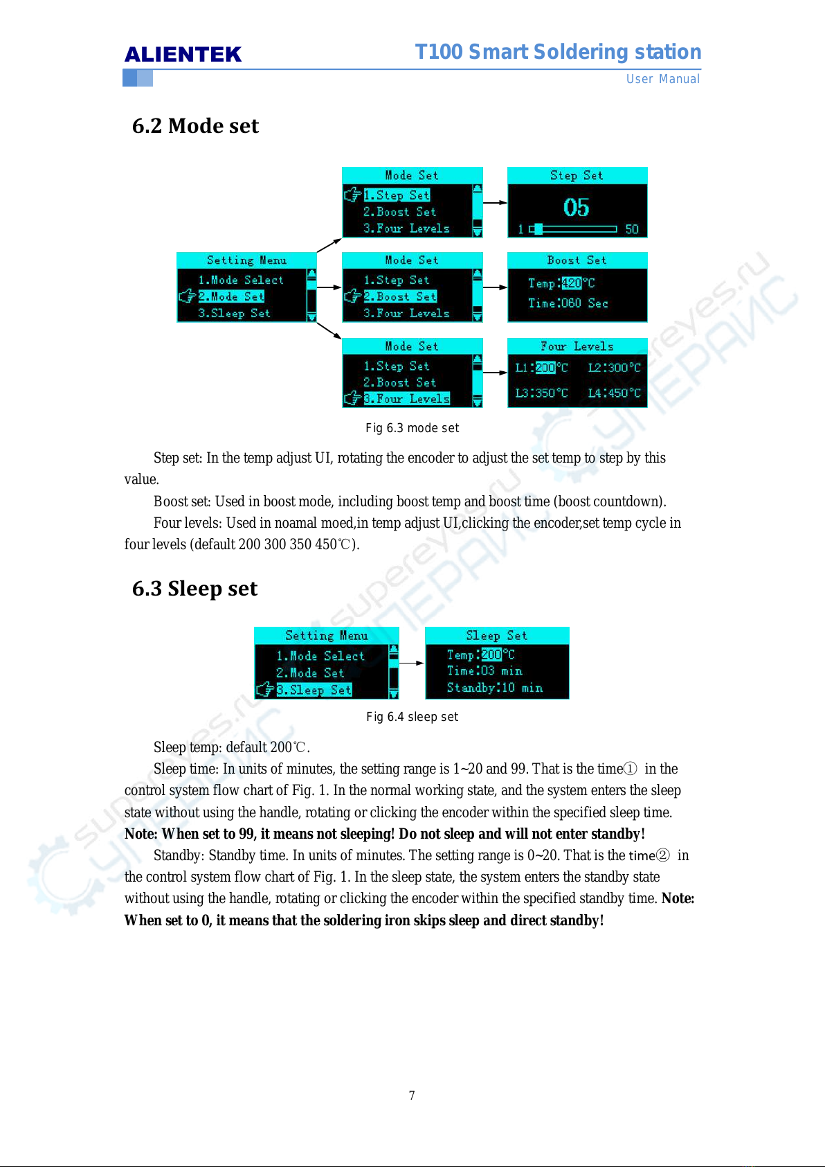
Fig 6.5 tip select
The system can save 6 tip calibration parameters, the user can select, calibrate and save any
one. (Note: the factory default selection of the tip 1 is suitable for the tip of this soldering station)
6.5 Tip calibration
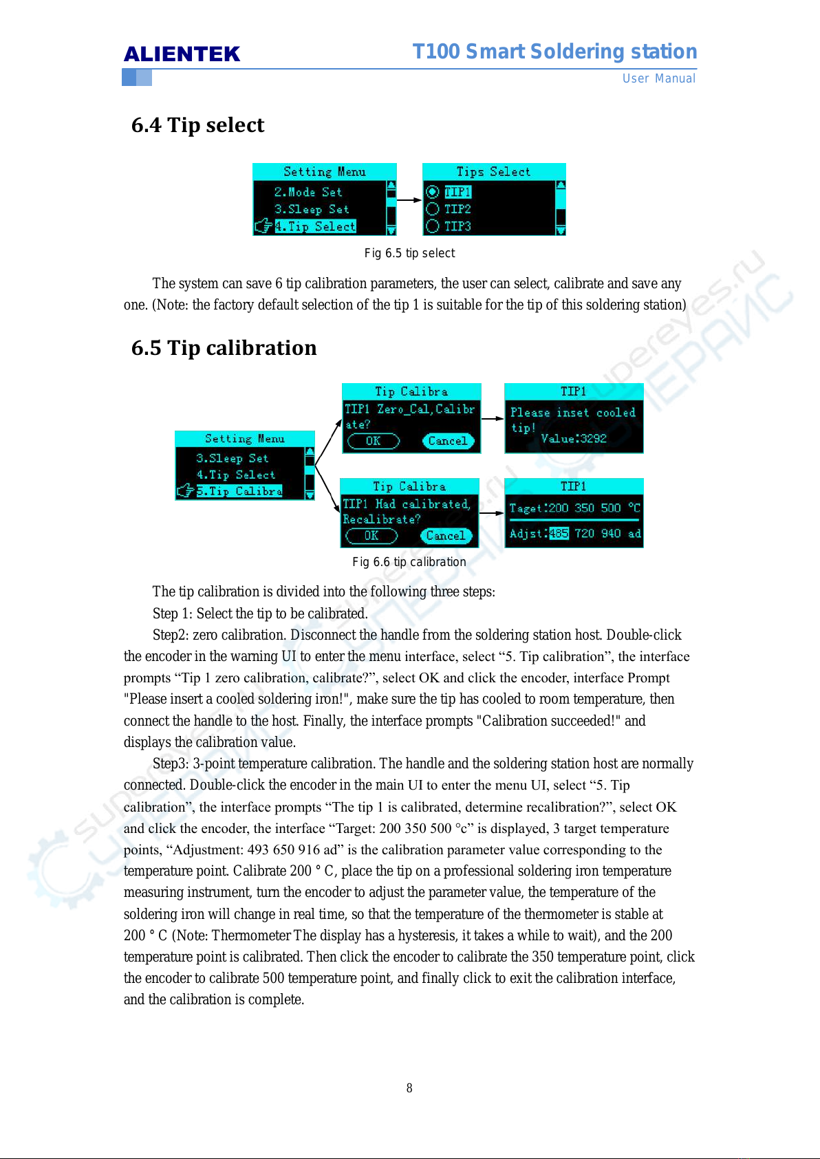
Fig 6.6 tip calibration
The tip calibration is divided into the following three steps:
Step 1: Select the tip to be calibrated.
Step2: zero calibration. Disconnect the handle from the soldering station host. Double-click
the encoder in the warning UI to enter the menu interface, select “5. Tip calibration”, the interface
prompts “Tip 1 zero calibration, calibrate?”, select OK and click the encoder, interface Prompt
"Please insert a cooled soldering iron!", make sure the tip has cooled to room temperature, then
connect the handle to the host. Finally, the interface prompts "Calibration succeeded!" and
displays the calibration value.
Step3: 3-point temperature calibration. The handle and the soldering station host are normally
connected. Double-click the encoder in the main UI to enter the menu UI, select “5. Tip
calibration”, the interface prompts “The tip 1 is calibrated, determine recalibration?”, select OK
and click the encoder, the interface “Target: 200 350 500 °c” is displayed, 3 target temperature
points, “Adjustment: 493 650 916 ad” is the calibration parameter value corresponding to the
temperature point. Calibrate 200 °C, place the tip on a professional soldering iron temperature
measuring instrument, turn the encoder to adjust the parameter value, the temperature of the
soldering iron will change in real time, so that the temperature of the thermometer is stable at
200 °C (Note: Thermometer The display has a hysteresis, it takes a while to wait), and the 200
temperature point is calibrated. Then click the encoder to calibrate the 350 temperature point, click
the encoder to calibrate 500 temperature point, and finally click to exit the calibration interface,
and the calibration is complete.