Note:Never file the tip to remove oxide.
7
3. If there is black oxide on the solder- plated portion of the tip, apply
new solder (containing flux) and wipe the tip on the cleaning ball.
Repeat until the oxide is completely removed. Coat with new solder.
The solder protects the tip from oxidation and prolongs the life of the
tip.
4. If the tip is deformed or heavily eroded, replace it with a new one.
A “dead” tip is one not wetted with solder. This exposes the plating to
oxidation and degrades the heat transfer efficiency of the tip. “Dead” is
caused by:
●Impurities in the solder, iron plating, or on the surfaces to be
soldered.
●Failure to keep the tip covered with fresh solder during idling periods.
●High tip temperatures for long time.
●Wiping the tip on dirty or dry sponge and rags. (Always use a clean,
wet, industrial grade, sulfur-free sponge or ball)
Recover a “Dead” Tip
1. Remove the tip from the solder handle and allow the tip to cool down.
2. Remove oxides from the tip with 80-grit abrasive polyurethane foam
stock or a 100-grit emery cloth.
3. Warp rosin core solder(Ø 0.8mm or larger)around the newly
exposed iron surface, inset the tip into the handle, and turn on the
station.
Note:Proper daily care can prevent “Dead” tip!
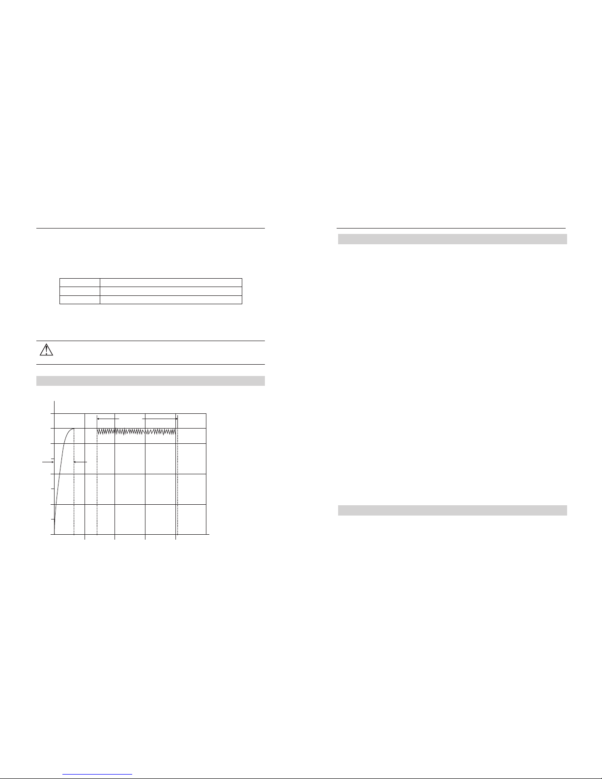
Extend tip life
1. Coat the tip with new solder after each use. This protects the tip from
oxidizing, prolonging tip life.
2. Try as low temperature as possible.
3. Use fine point tips only when necessary. The plating on fine precision
tips is less durable than the plating on thick tips.
4. Do not use the tip as a prying tool. Bending the tip can cause the
plating to crack, shortening tip life.
5. Use the minimum activation flux necessary to do the job, higher
activation flux is more corrosive to the tip plating.
6. Extend tip life by switching the system off when not in use.
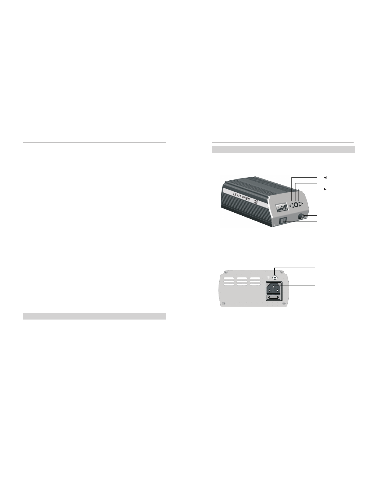
Parameter
Password setting
Enter Passwor d
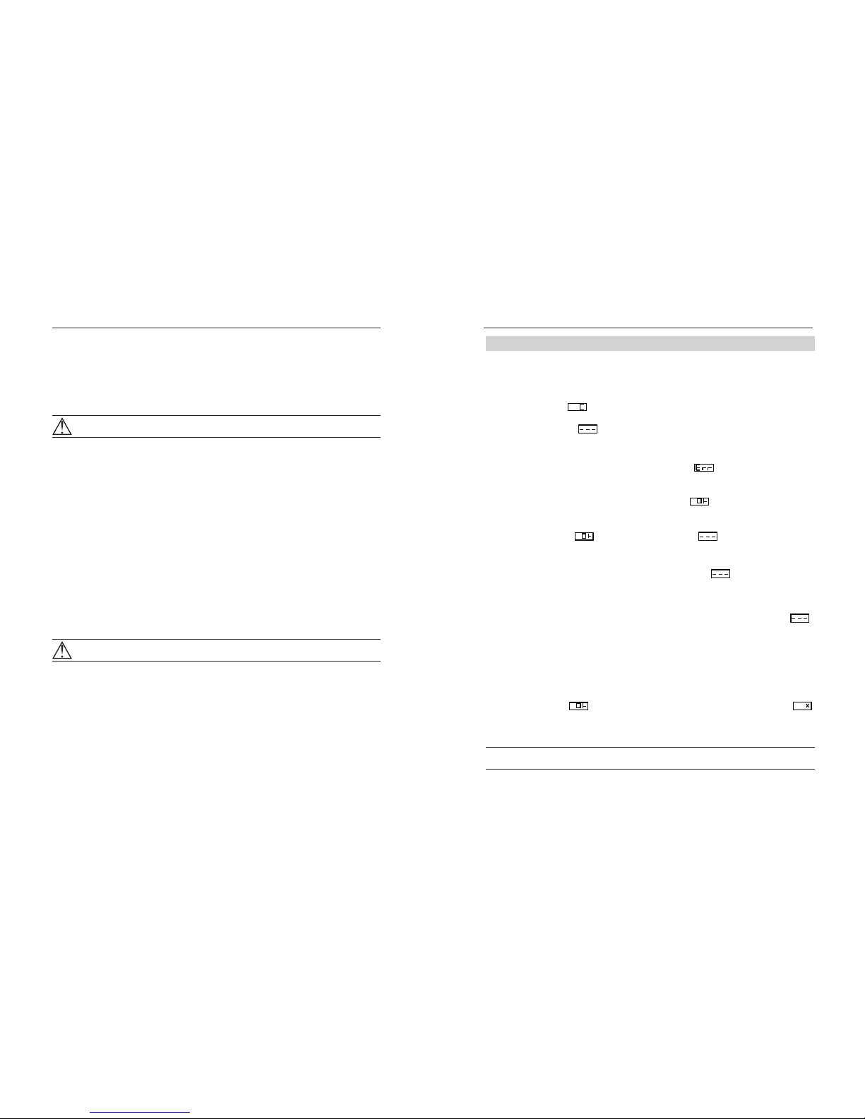
1. Press and hold ◄ and ►together, then power on.
2. It will Display which means entered password function.
Input original Password
1. Press◎,display ,the left digit will flash, and press ◄ or ►to enter
password number.
2. After enter all number, press ◎ to confirm.
● If the password is incorrect, display , soldering station will
enter work mode after 2 seconds and the temperature can not
be adjusted.
● If the password is correct, display , soldering station will
enter work mode after 4 seconds and the temperature can be
adjusted.
3. While display , press ◎ to display , means enter new
password. Press ◄ or ► to enter new password.
Re-input New Password
1. After enter 3 digit number, press◎,display ,means enter new
password to confirm, please input again.
2. If the two times password are same, after press ◎, password modify
successful and new password will be remember in machine.
3. If the two times password are not same, after press ◎, display ,
you have to re-enter the password, until the last two times number
are same.
Clean Passwor d
The initial password is “000”. Press and hold 3 keys and power on, the
password will change back to original password.
Work mode setting
1.While display , press ◄ and ► at the same time, display ,
means enter into work mode setting. Press ◄ or ► can change
working mode between mode 0 and mode 1.
Note: “×” stands for work mode number.
4