10
C. AUTOMATE FUNCTION
The system is equipped with a 5 stage automated hot air rework
profiling system. To access and change the time and temperature
settings of the profile follow the guide below:
1. Ensure that the hot air gun function switch is deactivated.
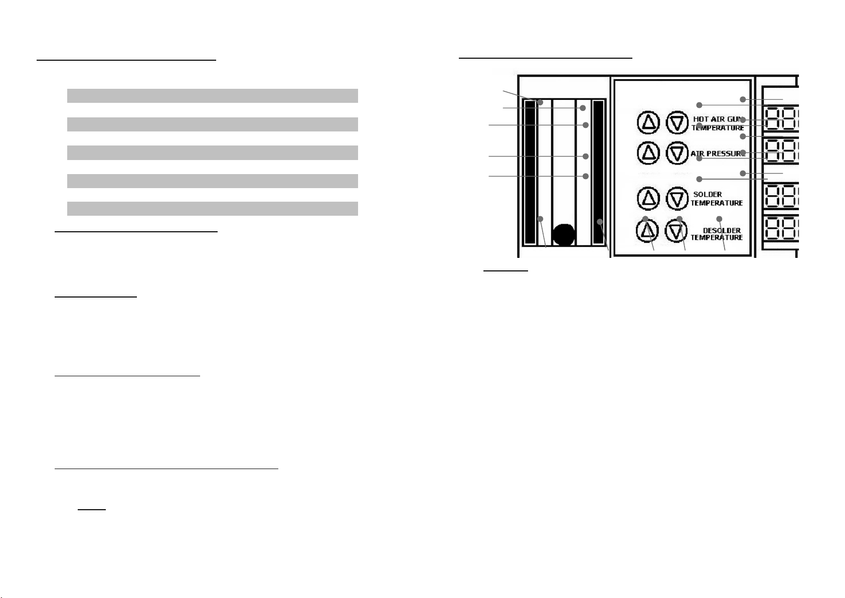
2. The Hot Air Gun Automate Function Selector (“17” from the control
panel) allows us to scroll thru the different stages of the profile.
The stages use the symbols A, b, c, d and E, to indicate stages 1 to
5 respectively. The Automate Display (“18” form the control panel)
shows the desired temperature for each stage and the Automate
Display (“16” form the control panel) shows the duration at which
the set temperature is to be maintained.
3. Now press the Hot Air Gun Automate Function Selector , the display
will change to “###A,” and “###t”. The suffix A indicates that we
are now adjusting the desired temperature for stage 1. The suffix
“t” indicates the time in seconds the desired temperature is to be
maintained.
4. Use the Hot Air Gun Temperature Adjustment Buttons to select the
desired temperature for this stage. Use the Hot Air Gun Airflow
Adjustment Buttons to select the desired duration. Adjust the
temperature/ duration of the other stages. Simply press the Hot Air
Gun Automate Function Selector to scroll to the next stage. Then
use the respective keys to adjust temperature and duration.
5. To save the newly inputted profile into memory, repeatedly press
the Hot Air Gun Automate Function Selector until the display shows
“SAUE”. Press the up button of the Hot Air Gun Temperature
Adjustment Button to confirm saving of the profile.
OPERATING GUIDELINES
19
J. Utilizing the Solder Iron Digital Temperature Calibration
By default, the system is properly calibrated but for some cases
when a little adjustment of the soldering iron temperature is required
the following procedure can be done.
1. Turn on the soldering iron function switch.
2. Set to appropriate temperature you want to calibrate. Place the tip
of the soldering iron on an external temperature meter.
3. The readings on the external temperature sensor should be more
or less equal to the displayed temperature.
4. If there are large discrepancy in the temperature reading we can
re-calibrate the temperature setting. First write down the set
temperature of the soldering iron and the actual temperature
reading from the external temperature meter. For example:
set temperature =350
external temperature = 300
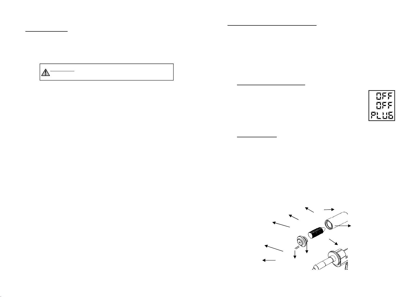
5. Turn off the Soldering Iron Function switch (“14” from the control
panel) .Ensure that the Desoldering Gun Function switch is in the
off position(“12” from the control panel) .
6. Press and hold the UP button of the Desoldering Gun
Temperature Adjustment button (“5” from the control panel) .
7. The Soldering Iron Temperature Display (“11” from the control
panel) . Will switch to four zeros “000” indicating it is now in the
soldering iron calibration mode. Release the UP button of the
Desoldering Gun Temperature Adjustment button
8. Use the Soldering Iron Temperature Adjustment buttons (“4” from
the control panel) to increase or decrease the calibration values.
In our example the set temperature is 350 but the actual
temperature is 300, There is a difference of 50 degrees. Press the
up button until we reach “050 ”.
9. Confirm the change by pressing and holding the “UP” button of
the Desoldering Gun Temperature Adjustment button (“5” from
the control panel).
OPERATING GUIDELINES