Align AL/CE-500P User manual

Iq
L\LIGN
PO"J'1EF~
-f).\3LE
FEED
UP
EFi;.YfJ9J\J J~J).\J\JU).\L
~,
,
\\,'\
No.G00399

CONTENT
PAGE INDEX
1 SPECIFICATION
2 WARNNING
3HOW TO INSTALL THE LONGITUDINAL FEED
4 HOW TO INSTALL CROSS FEED
5 HOW TO INSTALL KNEE LIFT FEED
6ASSY-L1MIT ASSEMBLY
6-8 PARTS LIST
9-10 SCHEMATIC DIAGRAM OF PARTS
11 CIRCUIT DIAGRAM
12 HOW TO INSTALL TRANSMITTER OF TR-1
13 HOW TO INSTALL TRANSMITTER OF TR-2
14 TROUBLE SHOOTING
CONGRATULATIONS ON YOUR NEW PURCHASE OF OUR POWER FEED
Please read this manual carefully before installation and using it. It will also
help you to solve some easy problems by yourselves. Hope our product
will bring you more effective and joyful working.
SPECIFICATION
I
Bevel
Model R.P.M Max Drive Max Rated Rated
R.P.M Gear Torque Voltage Current
Rate
AUCE-500P 0-160 160 4.8: 1 780 in-Ib 110V 50/60Hz 1Amp
VOLTAGE AS 220V-440V HAVE TO ADOPT TRANSFORMER

WARNNING
Please make sure if power supply be turned off
before assembly, and avoid from accident
caused during procedure of assembly.
Please take apart the drill and remove worked
item before assembly.
Please adjust suitable length of cord and watch
out the wiring, never pressure power cord by
clog then ambroin broken case short or spark.
Please don't disassemble for fixing or
refitment and free from accident or break
down caused by unhealth assembly.
Please make sure input voltage for power feed
as A.C.110V and avoid wrong power then burn
down circuit board, except A.C. 11OV,please
adopt the transformer.
A.
C.
II
av
6J
Please don't set the power feed in excessive
wettish working zone and don't wash down
the power feed by water or water shipped
then cause short or spark.
2

HOW TO INSTALL THE LONGITUDINAL FEED(X TYPE)
Adaptor Shim washers
Bearing face
Locking nut
Shim
Anti-Vandal Switch
The indicator LED will lit up
when the power is on.
Speed control knob
Circuit breaker Main power switch
When the current passing through the
switch is over 3.15A within 10 seconds,
it will automatically break the circuit.
To continue the operation, press down
the green-pusher and the power
indicator will glow.
"ON" position, power is "ON".
"OFF" position, power is"OFF".
3

HOW TO INSTALL CROSS FEED(Y TYPE)
HOW TO INSTALL T-WAY TRACK FOR CROSS-FEED
T-way bar and bracket for limit switch are
designed for simple installation on cross
slide.
-_II"
::;:::JC=I~"""" •.•~~~~~--
FIXED SUPPORT
T-WAYTRACK
L- ~~~~
STOP BLOCK
INSTALLATION INSTRUCTIONS
For ideal installation. You should not modify the cross travel lead screw.
CROSS TABLE FIT POWER FEED BODY
STAND
CROSS FEED BODY
HOW TO INSTALL T-WAY TRACK FOR KNEE-LIFT FEED
T-WAYTRACK
ASSEMBLY LIMIT SWITCH
VIEW OF LIFT SIDE OF KNEE
AND COLUMN
SCREW
CABLE CLAMP
SPRING STOP BLOCK
SOCKET HEAD CAP SCREW
4

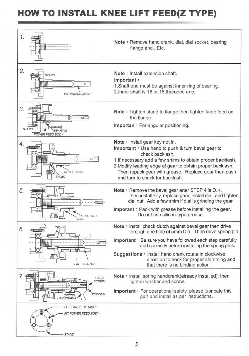
HOW TO INSTALL KNEE LIFT FEED(Z TYPE)
1.
2.
3.
4.
5.
6.
7.
Note: Remove hand crank, dial, dial socket, bearing
flange and ...Etc.
Note: Install extension shaft.
Important:
1.Shaft end must be against inner ring of bearing.
2.lnner shaft is 16 or 18 threaded unc.
Note : Tighten stand to flange then tighten knee feed on
the flange.
Importan : For angular positioning.
Note: Install gear key not in.
Important: Use hand to push & turn bevel gear to
check backlash.
1.lf necessary add a few shims to obtain proper backlash.
2.Modify leading edge of gear to obtain proper backlash.
Then repack gear with grease. Replace gear then push
and turn to check for backlash.
Note: Remove the bevel gear arter STEP 4 is O.K.
then install key, replace gear, install dial, and tighten
dial nut. Add a few shim if dial is grinding the gear.
Imporant : Pack with grease before installing the gear.
Do not use silicon-type grease.
Note: Install check clutch against bevel gear then drive
through one hole of 5mm Dia. Then drive spring pin.
Important: Be sure you have followed each step carefully
and correctly before installing the spring pins.
Suggestions: Install hand crank rotate in clockwise
direction to heck for proper shimming and
that there is no binding action.
Note: Install spring handcrank(already installed), then
tighten washer and screw.
Important: For operational safety, please lubricate this
part and install as per instructions.
5

ASSY-LIMIT ASSEMBLY
CAUTION
1.1twill damage the gear of power feed if you suddenly change the direction of power feed by
pushing the direction control handle while the machine is under high-speed operation.
If you intend to change the direction, please push the handle to the "off" position.
Waiting until the machine is completely stopped, then push the handle to your intended
direction.
2.Please make sure the position of the stop screw for your milling machine is keeping on
"loose" status.
3.While the power feed is under operation, please don't change to use manual control the
direction suddenly.
I
4.POWER FEED can only move to one direction.
Check: If ASSY-LiMIT SWITCH is normal.
S.Touch ASSY-LiMIT SWITCH POWER FEED in-between the TABLE and unable to stop it.
CHECK: If ASSY-LiMIT SWITCH is normal.
PARTS LIST
NO. PART NAME PART NO. SPECIFICATION REMARK
1 ALlCE-500P TOP HOUSING PTOOO-12
2180
0
CONTROL HANDLE P01810-12
I
90
0
CONTROL HANDLE P01816-12
I
3 SPEED CONTROL KNOB P01811-03 <t>35.5x <t>29.9x19mm
4 HANDLE KNOB E0913-03 <t>31.8x33mm
5ANTI-VANDAL SWITCH C0509
6INNER RING A0101B <t>24x16mm
7 NEEDLE BEARING A0101C <t>24x
<D
32x16mm
8AUCE-500P UPPER CLUTCH ASSEMBLY PT200
9DIRCTION SWITCH ASSEMBLY C0501-6V
10 CAP OF CIRCUIT BREAKER A0102-01
I
11 CIRCUIT BREAKER A0102 3.15A 125VAC
12 CAP OF ON-OFF SWITCH E0907-01
<D
21 X
<D
11X25mm
13 ON-OFF SWITCH E0907 R13-25A
14 BRAKE SWITCH ASSEMBLY C0508 6A 125V-250AC
15 AL-500P ADAPTOR PZOO~-13
16 SPRING FOR TOP HOUSING A01·2 11.5X 1.4X20mm
6

PARTS LIST
NO. PART NAME PART NO. SPECIFICATION REMARK
17 SPRING OF CLUTCH A0301-05 8.5X11.5X20mm
18 LIFT FORK ASSEMBLY PB300
19 LlFTFORK RING P01028
20 ARMATURE MOUNT P01082
21 SP ARMATURE ASSEMBLY P01907
22 MOTOR FIELD E0926V
23 CARBON BRUSH CAP E0906 <l>11.7X<l>5X5mm
24 BRUSH E0905 <l>8X6.1X37.5
25 CARBON BRUSH HOLDER P01004
cp
16.6X
cp
15.4X22.5mm
26 500P CAM ASSEMBLY E0902V
27 POTENTIOMETER ASSEMBLY P01905 10K
28 STRAIN RELIEF E0917
29 CONTROL CORD E24002 0.75X4CX1.7M
30 POWER CORD E23017 0.75X3CX2.7M
31 AL LIMIT SWITCH ASSEMBLY P01910-AL
CE LIMIT SWITCH ASSEMBLY P01910-CE
32 MICRO SWITCH F1104 10.1A250AC
33 PLASTIC GEAR ASSEMBLY PB800
34 PLASTIC GEAR PB801 <l>91.5X15X107T
35 AL-500P/AL500D BOTTOM COVER PO1809LS-03
36 X AXIS TRAVEL STOP ASSY P01916-1 2 PCS
Y.ZAXIS TRAVEL STOP ASSY P01916
37 BEVEL GEAR XIY (STANDARD) P01017
5/8" x1/8"
BEVEL GEAR Z (STANDARD) P01032 22x4mm
BEVEL GEAR P01054 20x6
38 BEVEL GEAR NUT A0100-01
1/4"
X20W
39 JC-10A CIRCUIT BOARD PB400
40 CIRCUIT BOARD INSULATOR E0918V 100X70XT1 mm
41 EXTENSION SHAFT (Z) P01922 16T STANDARD
EXTENSION SHAFT (Z) P01929 20T
42 T-WAYTRACK A0301-15A 59.5cm
T-WAYTRACK A0301-15B
I
66.5cm
T-WAYTRACK A0301-15D 29.5cm 2 PCS
43 ALUM STAND PFB-01A 28T
ALUM STAND PFB-02 35T
7

PARTS LIST
NO.
PART NAME PART
NO.
SPECIFICATION REMARK
43 IRON STAND PFB-18 13T
44 EXTENSION SHAFT PFB-07 L69mm
EXTENSION SHAFT PFB-08 L80mm
EXTENSION SHAFT PFB-16 L60mm
45 EXTENSION SHAFT RING PFB-03 L40mm
EXTENSION SHAFT RING PFB-04B L54.7mm
EXTENSION SHAFT RING PFB-09 L27mm
"
46 NUT PFR-76A 1/2-20X14.3mm
47 WASHER A0100-02A <1>45x <1>34xO .2mm
48 WASHER A0100-02B <1>45x <1>34xO .4mm
49 WASHER A0100-02C <1>45x <1>34xO.6mm
50 WASHER(COPPER) A0100-02D <1>45x <1>34xO.1 mm
51 WASHER A0100-04A <1>23.5 <1>16xO.2mm
52 WASHER A0100-04B <1>23.5 <1>16xO.4mm
53 WASHER A0100-04C <1>23.5<1>16xO.6mm
54 WASHER(COPPER) A0100-04E <1>23.5<1>16xO.1mm
55 WASHER A0100-07A <1>25.4 <1>16x2mm
56 PART'S KIT (X) P01911
57 PART'S KIT (Y) P01912
58 PART'S KIT (Z) P01913
II
8

-----IT]
(\'--'\7
,;;;;;>, \ :
'~4\ \
I
I . \ '\, /
"
'..-
'---,
3 "" ,,/
$_
.....- 0 .
o
l
I
I I
;
.
;
~20
to
1
I
~.-.-
~/
I
\
/
\
"
'
••.........
-
----
39
~38
40
@-37
----
............•
"
'\
/
\
/ e
~/~1
I
I I
I
I
\
/
\
/
\
/
\
/
'\
"
'
•.....
_-
--
35
44
--
'-
0 _
21

CIRCUIT DIAGRAM ALICE-SOOP
r---------~-----------------------
I Z I
I ~~ I
I
:I
I
I ~ I
I ""
II ~
!----"vv-----il ~ ~
II
co
I
Il
rr---------,
IN ~ ~
:~ s ~~~~
18
co
I;:;
IT ~
I~ ~
I
=r=
I
I
I
I
•
.----+-.~_'_llf__--_l
II
o
I
Q
11

HOW TO INSTALL TRANSFOMER OF TR·1 (ONE OUTPUT)
TRANSFOMER OF TR-1 IS USED FOR 220V, 240V, 380V AND 415V THEN TRANSFER
TO 110V. ATTACHING POWER PILOT LAMP AND ONE OUTPUT OUTLET.
ASSEMBLING GUIDE:
1.Make sure the voltage of working environment.
2.Choose the exact input point and well fix up.
3.Make sure whole screws of transformer are well locked.
4.Setting transformer on stable and dry wall.
5.Collecting cable and wire on the wire box of working plrce.
6.Keep from accident caused, don't disassemble and refit locked parts or
wiring of transformer when assembly proceeding.
TRANSFOMER
POWER CORD
CIRCUIT
415V~
I
::1:
V$
C\J
9
380V~
240
V
220V~
OV
PILOT LAMP OUTLET
12

HOW TO INSTALL TRANSFOMER OF TR-2(TW0 OUTPUT)
TRANSFOMER OF TR-2IS USED FOR 220V,240V,380V AND 415V, THEM TRANSFER
TO 110V. ATTACHING POWER SWITCH AND TWO OUTPUT OUTLET.
ASSEMBLING GUIDE:
1.Make sure the voltage f working environment.
2.Choose the exact input point and well fix up.
3.Make sure whole screws of transformer are well locked.
4.Setting transformer on stable and dry wall
5.Collecting cable and wire on the wire box of working place.
6.Keep from accident caused, don't disassemble and refit locked parts or wiring
of transformer when assembly proceeding.
OUTPUT OUTLET
POWER CORD
CIRCUIT
415V ~
~~~~
:
OV
OUTLET
13

TROUBLE SHOOTING
THE POWER FEED DOES NOT WORK AND THE POWER INDICATOR DOES NOT
GLOW:
1.Ensure there is no problem with power supply.
2.Check if the circuit breaker on the power feed unit kicked out.
3.Check for proper contact at the ON-OFF switch.
THE MOTOR DOES NOT WORK WHEN PUSH DIRECTION LEVER TO EITHER LEFT
OR RIGHT:
•
1.0pen power feed unit by loosening bottom 4 hex screws.
2.Check if the carbon brush is making proper contact with the armature or if carbon brus
h is all used up already.
3.Check that internal wiring to the printed circuit board ard all connected.
4.Check that the potentiometer connections ard intact and that it is functioning properly.
SPEED CONTROL ERRATIC OR ALWAYS AT HIGH SPEED ONLY:
1.Check rapid micro switch. Make sure it is not stuck. If its position is too high up,
lightly tap on it to lower.
2.Check V.R. Is in good connection and proper function.
BREAKER ALWAYS KICKS OUT ON POWER FEED UNIT UNDER NORMAL USAGE:
Short circuit in the armature, need to be replaced new armature.
CURRENT LEAKAGE:
1.Check limits switch assembly for possible short.
2.Check armature by first removing the brush cap.
3.Measure for short with an ohmmeter across the carbon brush and the outer cover of
the power feed unit.
14

Instruction for Power Feed installation ElmJJiiJJ~~,*~~)±~~I]l
ALIGN
Assembly illustration ~~n7.J\~1J
1. Suggested to check if all the connection accessories, hole distances to the center point
and angles are in standard before the installation.
2. Before you install Power Feed on the Milling Machine, please make sure the supplied
Longitudinal Bearing Bracket and Washer are match to Power Feed's fastening holes.
This is the key point for the installation.~
3. If you have found a little unmatched of the holes, try to ream the fastening holes on
Power Feed from <I>6.5 to <I>6.8 - <I>7. However, this is still a temporary solution. We still
suggest you to make sure everything is made as standard for the fundamental solution.
1.
~~~gM ' ~~$lCf@tJl~fflp2iim~G{!:j:, JL~e&Fi'3m~~C5~~$
0
2.m~~~n~~~~~~~gM'~$lCm~~fflp~~~m2iim~~.m~h'~~W~~~n~ii
m~AE2JL{rr' {~J~[DJ/~\[DJ~e' '8~~~~~JI[~fUW~2!U.1m
0
3.
~D5~miim~~.m~h~~~~~ , OJw:~~~~~~n~
4>6.5
~AEJL~JL~
4>6.8 - 4>7 '
tlDOJJI~fU
~~o~~m! •• ~OO~~~B$,m~.~2~~~iim~~.m~h~JLmm~~$m~.~o
If the holes are not match, fasten by force will cause the Lead Screw operating unsmoothly
and unusual sounds.
~ffJLm~g~.~~gfi.A'~.B~~~.~.~'&~~~n~~~R~o
G20362
100.07
Table of contents
Other Align Industrial Equipment manuals