Align PTT3 User manual

PTT3
Operation Manual
30,000 lbs. Capacity Battery Powered Tugger
ALIGNPROD.COM 800.888.0018
SUPPORT@ALIGNPROD.COM
PTT3 Power Tugger 2

PTT3 Power Tugger 3
Table of Contents
I. Important Precauons
II. Safety
III. Load Placement
IV. Sequence of Operaons
V. Baeries
VI. Maintenance
VII. Warranty
General Specifications
Model No. PTT3
Dimensions 61.3125” x 26.375” x 37.875”
Weight Approx. 800 lbs.
Capacity 30,000 lbs.
Battery 76 Ah
Charging 24 VDC / 12 A
Stroke 5.9”

PTT3 Power Tugger 4
I. Important Precauons
Read the following safety precautions before operating or servicing your equipment.
Follow correct lockout/tagout procedures.
Prevent personnel from leaning on equipment and containers or placing their arms, hands, legs or
any bodily member in pinch-point areas throughout the system.
Instruct personnel on the proper placement of product on the equipment. Failure to place containers
or loads in the engineered locations may hinder the operation of the equipment or cause structural
damage.
Never walk or climb into or onto the product while it is in motion.
Never alter the equipment in any way unless authorized by a qualified employee of Align.
Thoroughly read the manual and understand how to use the PTT3.
The operator should wear protective footwear at all times.
Keep the floors clean and smooth for efficient operation.
Keep the weight on the drive wheel while moving a load.
When driving the PTT3, try not to create any sudden stops / changes in direction.
Stop the unit slowly with the accelerator rather than letting go of the handle.
PTT3 Power Tugger 5
II. Safety
PTT3 Safety
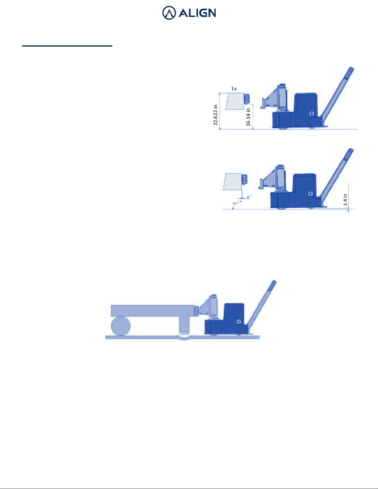
Charge the batteries after using the PTT3 Tugger.
Always place the female coupling (1a) at the correct
height. It’s important that the coupling is at the correct
angle and is firmly fastened to your trailer.
Raise / lift the coupling until the casters have enough
ground clearance (1.5”).
Only lift the coupling high enough to perform the transport.
Load Placement
The image below shows the correct setup that should be used with the PTT3, as well as where to
place the load. These trailers should consist of one wheel axle. When the trailer and the PTT3’s cou-
pling are attached to each other, and the PTT3’s arm is raised, the trailer leg will be lifted off
the ground.
As mentioned above, trailers should consist of one wheel axle. If there are two axles and the floor is
uneven, the front wheel will be lifted up by the PTT3 and overload the wheels. Uneven floors put the
trailer coupling at risk of unfastening and can disconnect from the trailer.

PTT3 Power Tugger 6
III. Load Placement
Load Placement
The image below shows the correct setup that should be used with the PTT3, as well as where to
place the load. These trailers should consist of one wheel axle. When the trailer and the PTT3’s cou-
pling are attached to each other, and the PTT3’s arm is raised, the trailer leg will be lifted off
the ground.
As mentioned above, trailers should consist of one wheel axle. If there are two axles and the floor is
uneven, the front wheel will be lifted up by the PTT3 and overload the wheels. Uneven floors put the
trailer coupling at risk of unfastening and can disconnect from the trailer.
The PTT3 has a maximum load capacity of 6,614 lbs on the drive wheel under normal conditions.
The load capacity depends on the configuration of the load. Max capacity could be under 6,614 lbs.
depending on if there is a swing bearing or a lift cylinder. Contact Hedin USA if you unsure of your lift
capacity.
The drive wheel needs ground force on it to make sure friction between the floor and wheel provides
the traction required to perform the transport.
The load center has to be in between the trailer’s wheels and the PTT3’s drive wheel. If not, there is
a chance the load could overturn.
Heavier loads must be balanced on the trailer - see picture below.

PTT3 Power Tugger 7
IV. Sequence of Operaons
As operator, you are responsible that no one is in harm’s way whilst you are
operating the transporter.
Starting the Equipment
Turn the key switch on the handle when it is in its upright position.
Check the battery indicator to make sure the PTT3 is charged and ready for use.
Push the “lift cylinder down” button to assure that the cylinder is in its lowest position.

PTT3 Power Tugger 8
IV. Sequence of Operaons
As operator, you are responsible that no one is in harm’s way whilst you are
operating the transporter.
Connecting the PTT3 to a Trailer
Ensure the coupling between the PTT3 and the trailer is properly connected.
When the lift is performed, do not lift higher than necessary as it puts additional strain on the
lift cylinder.
The casters at the back of the PTT3 will lift from 1.5” from the floor. This applies the load to the drive
wheel for easy maneuverability.
The coupling must be attached vertically so the casters in the back of the PTT3 are in the air when it
has been connected to the trailer.
If the trailer is fixed to the PTT3, the casters can be removed to avoid becoming stuck on
uneven floors.
Connecting the PTT3 to a Trailer
The direction and speed of the PTT3 is controlled and adjusted by the accelerator at the top of the
handle.
A safety switch is located on the handle. When triggered, the PTT3 will stop and take a small leap
forward to prevent the pinning of the operator.
PTT3 Power Tugger 9
IV. Sequence of Operaons
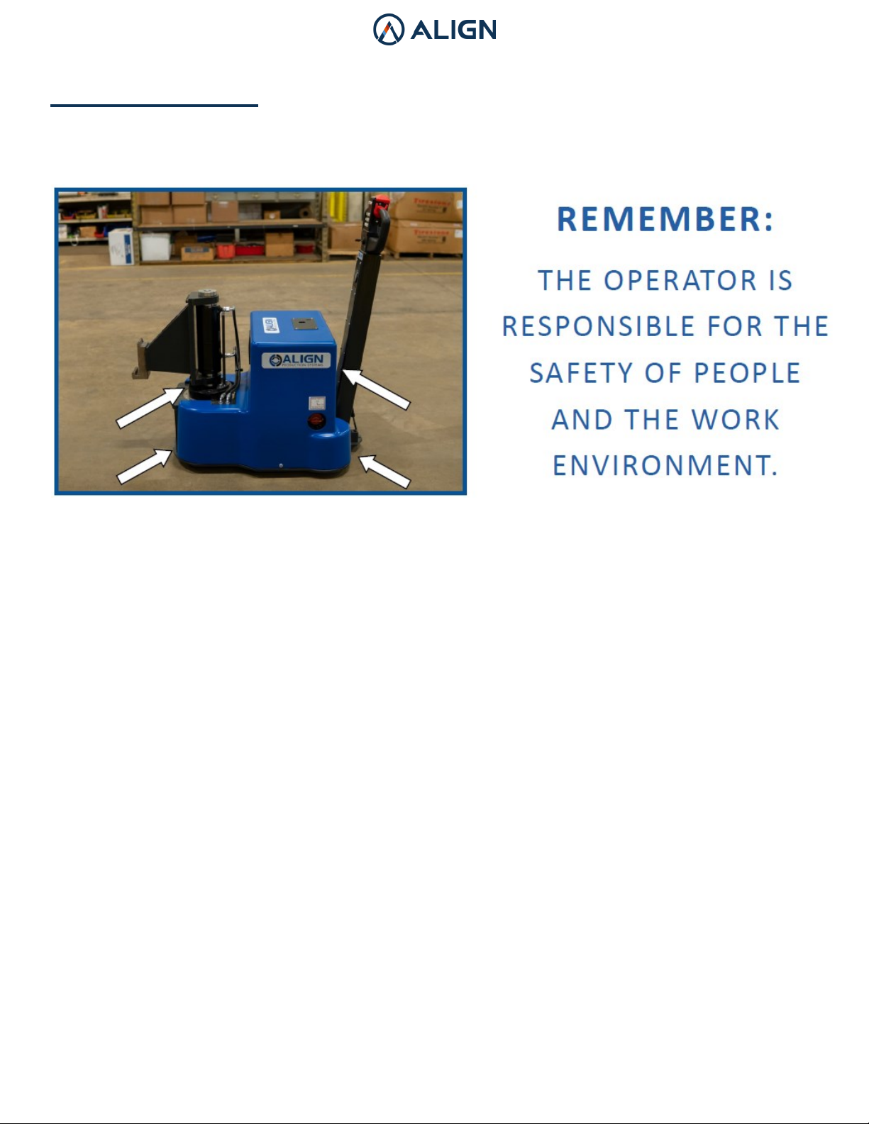
Pinch Points
Be careful of pinch points. They can occur:
• Between the PTT3 and moving or fixed objects
• During lifting—between the floor and the PTT3 or between the object being connected and the
PTT3.
• When operating the hydraulic cylinder.
• While driving the PTT3. Be cautious of surroundings.

PTT3 Power Tugger 10
V. Baeries
Charging the Batteries
Always switch the battery charger off before connecting / disconnecting the battery cables.
The batteries are to be charged a minimum once a week to maintain their capacity over time.
The charging cable is to be connected to the outlet on top of the PTT3.
“Charging” is indicated by a yellow light.
“Charge Complete” is indicated by a green light.
The charger has an extra green light which indicates that the charging current (1 Ah) is not reached
in the maximum charging time of 20 hours to prevent overcharging and harm to the battery.
Table of contents
Popular Lifting System manuals by other brands

probst
probst SDH-H-15 operating instructions

Bruno
Bruno OUTDOOR ELITE CRE-2110E Operator's manual

matev
matev FPS Mounting Assembly Installation Guide

Vestil
Vestil CYL-HLT Series instruction manual

Butts Tools
Butts Tools BXS0002 operating instructions

Safelift
Safelift MoveAround MA60 Original instructions


R. Beck Maschinenbau
R. Beck Maschinenbau HS 600 operating manual

Nova Technology International, LLC
Nova Technology International, LLC NAS Series quick start guide

Genie
Genie Z-60/34 Operator's manual

Screen Technics
Screen Technics INTERFIT Vertical Up Lift instructions

Drive
Drive DUPONT SAMERY Hermes user manual

Custom Equipment
Custom Equipment Hy-Brid 3 Series MAINTENANCE & TROUBLESHOOTING MANUAL