manuals.online logo
Brands
  1. Home
  2. •
  3. Brands
  4. •
  5. Basta Boatlifts
  6. •
  7. Lifting System
  8. •
  9. Basta Boatlifts Over-Center 18k59 User manual

Basta Boatlifts Over-Center 18k59 User manual

READ complete manual CAREFULLY
BEFORE attempting assembly or operation
tm
Over-Center Hydraulic Steel Lift
18,000 lbs Capacity Models # 18k59 &18k71
ASSEMBLY
INSTALLATION
REPLACEMENT PARTS
18k59/71
11/21
L392-0067, REV D
Copyright 2015 Basta Marine
©
866-GO-BASTA
www.gobasta.com
Basta Marine, Inc. Bellevue WA 98005 USA
Assembly Instructions .........................................................................Pages 4 - 12
First Use / Adjustments
..……………...........................................................Page 13
Basta Marine Boat Lift Accessories ....…………………....…………..…...Page 16
Parts Assembly Diagram .............................................................................Page 3
Troubleshooting / FAQ .…...........................................................................Page 14
INDEX
Warning ..……………………..............................................................................Page 2
Warranty .............................…...........................................................................Page 15
NOTE:Your boat lift is a very heavy piece of equipment. Improper use could result in
serious injury or death. For the safety of people and property please review the safety
guidelines below for your new boat lift.
Passengers should stand clear of the lift and not
be aboard when the lift is in operation.
Do not play on or near the lift.
Leave your automatic bilge pump turned on the
automatic setting to prevent the accumulation of
rain water.
Service your lift regularly.
Do not service the unit with the boat on the lift.
Use a mooring line for additional security.
Only use Basta Marine approved oil in lift.
Special biodegradable non-toxic hydraulic fluid
Visually inspect all parts and assemblies for
defects and damage prior to assembling the
lift.
Do not install the lift alone.
Install the lift on firm and level ground.
Verify the lower frame of the lift is level
before each use.
Turn the power off during periods of non- use.
This hoist is a heavy piece of equipment please
use with care.
The lift should not be used for any other
purpose besides the lifting of boats & watercraft.
WARNING
part # Y354-0001
page 2
Do not exceed the maximum weight capacity
specified for the lift. SEE PAGE 18.
MAXIMUM CAPACITY
DANGER
18,000 LBS
8 200 KG
For a full list of patents, go to:
bastaboatlifts.com/patents
INSPECT
the lift monthly
for frayed hoses, loose
fasteners and corrosion
Before Using:
Read this manual
completely!
!
!
!
lift unattended
OIL INJECTED INTO THE SKIN FROM HIGH PRESSURE
LEAKS IN HYDRAULIC SYSTEMS CAN CAUSE SEVERE
INJURY. MOST DAMAGE OCCURS DURING THE FIRST
FEW HOURS. SEEK MEDICAL ATTENTION IMMEDIATELY.
SURGICAL REMOVAL OF OIL MAY BE NECESSARY.
USE ONLY BASTA APPROVED BIODEGRADABLE HYDRAULIC FLUID
page 3
After the lift is assembled and installed, all fasteners should
be checked for proper tightness and reinspected
periodically.
!WARNING
13
14
6
5
2
1
2
4
7
10
9
17
16
ITEM PART # DESCRIPTION
1base crossmember weldment, forwardW110-0007
QTY
1
2
3
4
5
6
7
8
9
10
11
12
13
14
15
16
17
18
19
20
20
21
22
base crossmember weldment, aft
side rail weldment, left
side rail weldment, right
H-frame weldment, forward
H-frame weldment, center
H-frame weldment, aft
bunk chevron weldment
bunk board assembly, forward
bunk board assembly, aft
bunk stanchion
bolt plate, bunk
foot weldment
leg
bunk rail weldment
hydraulic cylinder
keel board
centering device bracket
centering device stanchion tube
centering device buffer tube
centering device buffer tube cap
lower unit stop
lower unit stop spacer
W110-0008
W104-0022
W104-0023
W101-0038
W101-0039
W101-0040
W113-0018
A428-0014
A428-0015
K204-0022
K204-0036
W116-0003
K200-0064
W113-0020
see page 15
W410-0051
W108-0030
W108-0003
K204-1013
K204-1014
W410-0049
K204-0082
2
1
1
1
1
1
4
2
6
16
16
6
6
2
4
1
2
2
2
2
2
4
3
15
15
10
11
12
10
page 4
In the following pages various symbols are used:
indicates an illustration for a procedure.
indicates a major part shown and described above.
indicates a hardware item shown and described on page 5.
12
1
C3
8
I T E M S 1 7 - 2 2
ARE SHOWN ON
PAGES 16 & 17
ITEM PART # DESCRIPTION
1base crossmember weldment, forwardW110-0007
QTY
1
2
3
4
5
6
7
8
9
10
11
12
13
14
15
16
17
18
19
20
20
21
22
base crossmember weldment, aft
side rail weldment, left
side rail weldment, right
H-frame weldment, forward
H-frame weldment, center
H-frame weldment, aft
bunk chevron weldment
bunk board assembly, forward
bunk board assembly, aft
bunk stanchion
bolt plate, bunk
foot weldment
leg
bunk rail weldment
hydraulic cylinder
keel board
centering device bracket
centering device stanchion tube
centering device buffer tube
centering device buffer tube cap
lower unit stop
lower unit stop spacer
W110-0008
W104-0022
W104-0023
W101-0035
W101-0036
W101-0037
W113-0018
A428-0014
A428-0015
K204-0022
K204-0036
W116-0003
K200-0064
W113-0019
see page 15
W410-0051
W108-0030
W108-0003
K204-1013
K204-1014
W410-0049
K204-0082
2
1
1
1
1
1
4
2
6
16
16
6
6
2
4
1
2
2
2
2
2
4
MODEL 18k71MODEL 18k59
C
B
B
B
D
F
A
J
G
H
E
ITEM PART # DESCRIPTION
A1 5/8” x 1-1/2” hex head set screw, SSS103-0807
QTY
24
B1
B2
B3
C1
C2
C3
D1
D2
D3
E1
E2
F1
F2
F3
G1
G2
G3
H1
H2
H3
J1
J2
J3
K1
K2
K3
L1
M1
M2
M3
1/2” x 1-1/2” hex head cap screw, SS
1/2” flat washer, SS
1/2” nylon insert lock nut, SS
1” x 9” hex head cap screw, SS
1” flat washer, SS
1” nylon insert lock nut, SS
3/4” x 5” hex head cap screw, SS
3/4” flat washer, SS
3/4” nylon insert lock nut, SS
ring type cotter pin, SS
3/4” x 3-1/2” clevis pin, SS
1/2” x 3-1/2” hex head cap screw, SS
1/2” flat washer, SS
1/2” nylon insert lock nut, SS
3/8” x 5” hex head cap screw, SS
3/8” x 3-1/4” hex head cap screw, SS
3/8” flat washer, SS
3/8” flat washer, galvanized
3/8” nylon insert lock nut, SS
3/8” lock washer, galvanized
3/8” hex nut, galvanized
3/8” x 3” hex head cap screw, SS
3/8” flat washer, SS
3/8” nylon insert lock nut, SS
5/16” flat washer, galvanized
5/16” lock washer, galvanized
5/16” hex nut, galvanized
1/2” x 1-1/4” sq head set screw,SS
S103-0707
S313-0010
S362-0010
S103-1020
S313-4015
S362-0014
S103-0912
S313-0013
S362-0012
S522-0801
S503-0013
S103-0715
S313-0010
S362-0010
S103-0519
S313-0008
S313-0008
S312-0008
S362-0008
S362-0008
S321-0008
S341-0008
S103-0513
S313-0008
S362-0008
S312-0007
S321-0007
S341-0007
S103-0514
S163-6711
24
48
24
6
6
6
6
6
6
8
8
16
32
16
32
64
32
16
32
16
4
4
4
12
24
8
12
8
8
12
page 5
A
B
F
C
GE
D
H
J
ITEMS K1 THROUGH M3 ARE
SHOWN ON PAGES 16 & 17
ASSEMBLY INSTRUCTIONS
1
1
1
3
2
2
3
Foot and Leg Sockets
1
QTY SIZE TYPE
24 hex head set screws5/8 x 1-1/2
REF
A1
apply a small
amount of grease
to bolt threads
HARDWARE
1
1
2
2
tighten leg set screws
alternately to push the
leg securely into the
corner of the leg socket
A1
A1
A1
1
page 6
step
13
A1
14
1 or 2
?parts identified
on page 4
?parts identified
on page 4
Aft and Center Crossmembers Forward Crossmember
2
3
QTY QTYSIZE SIZETYPE TYPE
8 16
16 32
8 16
bolts3/8 x 1-1/4 3/8 x 1-1/4
3/83/8
3/83/8
REF REF
B3B3
B2B2
B1B1 bolts
flat washersflat washers
lock nutslock nuts
apply a small
amount of grease
to bolt threads
apply a small
amount of grease
to bolt threads
HARDWARE
HARDWARE
do not tighten these bolts
completely until the H-frames
and bunks have been
installed & squared up
do not tighten these bolts
completely until the H-frames
and bunks have been
installed & squared up
B2
B3
B1
B3
B2
B3
B1
B3
page 7
step
step
1
3 or 4
3 or 4
2
?parts identified
on page 4
?parts identified
on page 4
ASSEMBLY INSTRUCTIONS
page 8
Forward H-Frame
QTY SIZE TYPE
2bolts1 x 9
REF
C1
2
2
flat washers
lock nuts
1
1
C2
C3
4apply a small
amount of grease
to bolt threads
HARDWARE
4
5
6
remove the plastic ties
that secure the bushings
before installing the H-frame
C1
C3
C2
step
FORWARD CENTER AFT
REMOVE
5
?parts identified
on page 4
C3 C2
C1
Center H-Frame Aft H-Frame
remove the plastic ties
that secure the bushings
before installing the H-frame
QTY QTYSIZE SIZETYPE TYPEREF REF
6
5
apply a small
amount of grease
to bolt threads
apply a small
amount of grease
to bolt threads
HARDWARE
HARDWARE
C2 C3
C1
2 2bolts bolts1 x 9 1 x 9C1 C1
2 2
2 2
flat washers flat washers
lock nuts lock nuts
1 1
1 1
C2 C2
C3 C3
remove the plastic ties
that secure the bushings
before installing the H-frame
page 9
step
step
FORWARD
FORWARD
CENTER
CENTER
AFT
AFT
REMOVE
REMOVE
7
6
?parts identified
on page 4
?parts identified
on page 4
ASSEMBLY INSTRUCTIONS
Bunk Rails
QTY SIZE TYPE
6bolts3/4 x 5
REF
D1
6
6
flat washers
lock nuts
3/4
3/4
D2
D3
7apply a small
amount of grease
to bolt threads
HARDWARE
tighten these nuts only
“finger tight” until the
cylinders are installed
7
7
7
7
7
8
8
9
9
7
D3
D1
D2
page 10
step
15
15
LONGER
SHORTER
?parts identified
on page 4
Forward Hydraulic Cylinders Aft Hydraulic Cyinders
QTY QTYSIZE SIZETYPE TYPE
44
44
ring type cotter pinsring type cotter pins
clevis pinsclevis pins
3/32 x 23/32 x 2
3/4 X 53/4 X 5
REF REF
E2E2
E1E1
8
9HARDWARE
HARDWARE
E1 E2
E2 E1
install the clevis pins
“E2” with their heads
toward the inside of the lift
page 11
step
step
INSIDE
INSIDE
NOTICE
tighten the bunk rail nuts and
crossmember bolts after
all the cylinders are installed
16
16
16
16
?parts identified
on page 4
?parts identified
on page 4
Bunk Chevrons (4 total)
QTY SIZE TYPE
16 bolts1/2 x 3-1/2
REF
F1
32
16
flat washers
lock nuts
1/2
1/2
F2
F3
10 apply a small
amount of grease
to bolt threads
HARDWARE
leave bolts loose
until bunk boards
are installed
10
F3
F2
F1
page 12
step
10
10
10
12
11
at each
bunk board
50¾” 92” 92”
8
8
8
?parts identified
on page 4
approximate starting locations
¾”
129cm 234cm 234cm
Bunks (8 total)Keel Board
QTY QTYSIZE SIZETYPE TYPE
4 32
4
4
96
48
16
galvanized flat washers bolts
galvanized lock washers
galvanized nuts
flat washers
lock nuts
bolts
5/16 3/8 x 5
5/16
5/16
3/8
3/8
3/8 x 3
REF REF
J1
J2
J3
G2, H2
G3, H3
H1
G1
12
11
apply a small
amount of grease
to bolt threads
apply a small
amount of grease
to bolt threads
HARDWARE
HARDWARE
the bunks may have to be adjusted
several times for the best fit -
J2
J1
G1
H1
H2
H3
G3
page 13
step
step
remember to tighten all the
bolts installed in Step 10
NOTICE
8
11
17
11
12
12
?parts identified
on page 4
?parts identified
on page 4
G2
WITHOUT BOAT ON LIFT!
J3
13
7
9
8
12
6
14
4. Test the lift on dry ground using the Up/Down Switch
( # 9) and the Key Fob Transmitters. Inspect the
system for leaks.
1. The Hydraulic Pump will arrive fully assembled. Make
s u re all the connections are snug to prevent leaks or
loss of power to the unit.
2. Install two Group 31 Marine Grade Batteries as shown
a b ove. Confirm that the POWER switch on the Control
Panel (#8) is OFF. Connect the two solar panels to the
batteries as shown - each panel connects to one battery.
Connect the short Link Cable (#19) between the positive
terminal of one battery and the negative terminal of the
other. Connect the Red Battery Cable (#12) to the
positive terminal of the right battery and the Black Battery
Cable (#13) to the negative terminal of the left battery.
NOTE: Ensure battery cables are correctly connected
and their terminals are tight (use pliers).
3. Slide the Hydraulic Cylinder Hoses (#14) through the
a c cess holes in the side of the White Fiberglass Box
(#10) and attach them to their corresponding
Quick Couplers (#4, #5).
Ensure each Quick Coupler is
completely seated and tight with
no gap at the connection joint.
Connection must be tight to open internal
check valve and allow fluid to flow. USE PLIERS
one
inch
hydraulic fluid level with
lift in DOWN position
only add fluid with lift
in DOWN position
Hydraulic Power Unit
13 page 14
step
OIL INJECTED INTO THE SKIN FROM HIGH PRESSURE
LEAKS IN HYDRAULIC SYSTEMS CAN CAUSE SEVERE
INJURY. MOST DAMAGE OCCURS DURING THE FIRST
FEW HOURS. SEEK MEDICAL ATTENTION IMMEDIATELY.
SURGICAL REMOVAL OF OIL MAY BE NECESSARY.
Keep inside dry
2
NO GAP!
4
5
Tighten wingnuts on
batteries very tight.
Otherwise, cables
may overheat
during lift
operation.
NOTICE
19
++
From
Solar Panels
From
Solar Panels
Battery
Group 31
marine
deep cycle
Battery
Group 31
marine
deep cycle
From
Solar Panels
Isolation Diode
Isolation Diode
To Pump
To UP-DN Switch
page 15
# R285-1004
GROUP 31 DEEP
DISCHARGE
BATTERY
POWER UNIT
SUB-ASSEMBLY
# H603-0008
NOTE: battery
can not be
shipped
PUMP
ASSEMBLY
# H602-0007
17
1
Please order replacement parts by PART NO. and DESCRIPTION
CONTROL PANEL
ASSEMBLY
# R815-0002
pre-wired
with wiring
harness
COMPLETE HYDRAULIC POWER UNIT WITH ENCLOSURE & SOLAR # H653-0008
HYDRAULIC CYLINDER ASSEMBLY # H310-0018
1 call pump motor only
2 call miscellaneous hyd. fittings
3 n/a
4 call quick coupler assy, female
5 call quick coupler assy, male
17 call
high
current
solenoid
10 C243-0005 white fiberglass enclosure
11 R281-0002 solar panel assembly
ITEM PART NUMBER DESCRIPTION
PUMP ASSEMBLY # H602-0007
ENCLOSURE ASSEMBLY # C245-0006
CONTROL PANEL ASSEMBLY # R815-0002
14 H123-0019 hydraulic hose assembly
15 H412-5302 hydraulic cylinder
16 H791-0005 hydraulic fitting kit
20 H111-0002 hydraulic hose
ITEM PART NUMBER DESCRIPTION ITEM PART NUMBER DESCRIPTION
POWER UNIT SUB-ASSEMBLY # H603-0008
12 R711-1010 positive batt cable (red)
13 R711-1005 negative batt cable (black)
NOTE: pump
appearance
may vary
18
18 W421-0002 pump board
19 R711-1001 link battery cable
Hydraulic Fluid
# Y354-0001
14
15
# H310-0018
pre-charged
with hydraulic fluid
15
16
6 R815-0001 panel with graphics
7A R812-0010 remote control rcv (w/ 2 fobs)
7B R811-0009 remote control fob
8 R310-0001 rocker switch, on-off
9 R310-0002 rocker switch, raise-lower
(quart)
Prevent unauthorized use -
KEEP BOX LOCKED
10
11
Padlock
not included
Hydraulic Cylinder
Assembly
Item #16
on pg 4
20
NOTE: kit may vary from illustration
Remote Key Fobs
# R811-0009
7B
7A
Remote Control Receiver
with Harness
STD.
WIRING
NOT USED
NOT USED
LOWER (purp)
LAMP (yel or orn)
page 16
Centering Device Brackets
QTY SIZE TYPE
12 bolts3/8 x 3-1/4
REF
K1
24
12
flat washers
lock nuts
3/8
3/8
K2
K3
14 apply a small
amount of grease
to bolt threads
HARDWARE
up to four centering
devices per side
can be installed
14
step
14
14
16
15
14
position
as desired
position
as desired
position
as desired
position
as desired
18
K3
K2
K2
K1
?parts identified
on page 4
quantities shown
are for three pairs
of centering devices
page 17
Centering Device StanchionsLower Unit Stops
QTY QTYSIZE SIZETYPE TYPE
8 12
8
8
galvanized flat washers square head set screws
galvanized lock washers
galvanized hex nut
3/8 1/2 x 1-1/4
3/8
3/8
REF REF
M1
M2
M3
L1
16
15
apply a small
amount of grease
to bolt threads
apply a small
amount of grease
to bolt threads
HARDWARE
HARDWARE
remember to tighten
all the bolts installed
in Step 10
note how bunk chevron
fits between forward and
aft bunk board stanchions
step
step
21
19
20
?parts identified
on page 4
?parts identified
on page 4
M3
L1
M1
22
12
quantities shown
are for three pairs
of centering devices
M2
page 18
FIRST USE AND ADJUSTMENTS
Follow this “first use section” during your first loading of a boat onto the boat lift.
These are required adjustments to make the lift work correctly.
1. Place the boat over the lift to the following specifications:
a. If your boat is an outboard, inboard/outboard, or V-drive, the transom should be 2 inches off of the ends of the bunk boards.
b. If your boat is a mid-engine or shaft-drive, the transom should be 12 to 24 inches off of the ends of the bunk boards.
Disembark and raise the boat. If more than two inches of settling occurs, STOP, carefully lower the lift to remove the
boat and re-level the lift. Continue repeating this step until the boatlift can be raised into the full Over - Center position
without settling.
tm
3. Remove the boat. Verify that the lift frame is level. Re-level the framework if necessary.
NOTE: If you purchase a new boat, be sure it is within the weight capacity limits of the lift. Also remember that
these adjustments will have to be done again to accommodate the new boat.
First test lift on dry ground for oil leaks, remote control function and correct operation.
2.
IMPORTANT: After installation, the legs MUST be adjusted so that the lift frame is level.
Lift must move into Over-Center position when fully raised.
!
!
!
lift unattended
104”
[92”]
69”
[62”]
33”
24”
Where measurements differ, those for
the 18k59 are shown in [brackets].
Do not exceed the maximum weight capacity
specified for the lift. SEE PAGE 18.
MAXIMUM CAPACITY
DANGER
612cm
264cm
[234cm]
175cm
[157cm]
61cm 84cm
287cm
592cm
366cm
18,000 LBS
8 200 KG
page 19
MAINTENANCE
Occasionally wipe the solar panel with a clean, damp cloth to preserve its charging performance.
INSPECT THE LIFT PERIODICALLY
After the lift is assembled and installed, all fasteners should
be checked for proper tightness and reinspected
periodically.
!WARNING
one
inch
hydraulic fluid level with
lift in DOWN position
add fluid ONLY with lift
in LOWERED position
one
inch
hydraulic fluid level with
lift in UP position
NOTICE
USE ONLY BASTA APPROVED BIODEGRADABLE HYDRAULIC FLUID
We recommend Chevron Clarity® AW ISO 32 or CITGO Aquamarine® 46 hydraulic oils.
DO NOT add fluid with
lift in RAISED position
!
Once a month:
Inspect the hoses, cylinders and fittings for leaks and wear.
Check the wire terminals for snugness and corrosion.
Check the hydraulic fluid level.
At least every 6 months:
Check the battery levels.
The battery electrolyte should be slightly
above the indicator ring in each cell. Carefully
add DISTILLED water if necessary
Do not over-fill.
BLK RED
NOT
USED
page 20
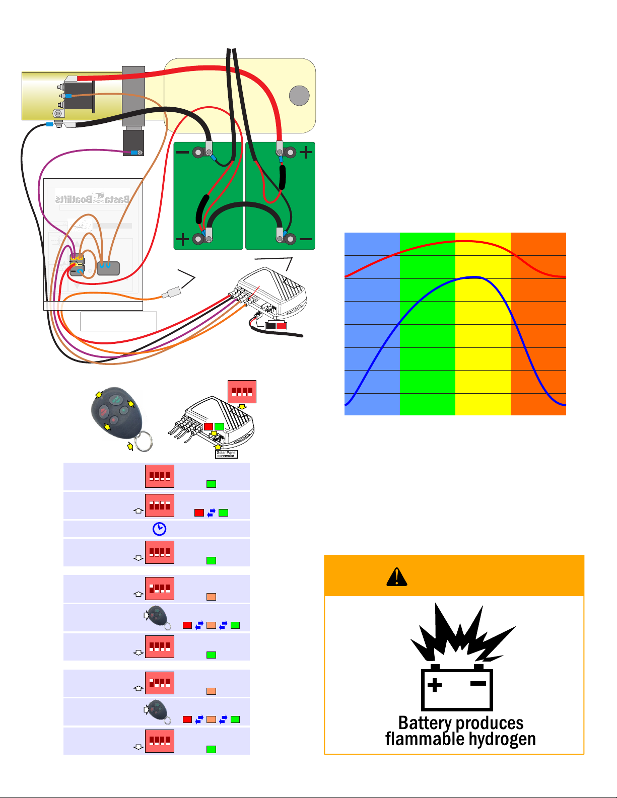
Reprogramming Key Fobs
A fully automatic battery charger or
trickle charger may be used.
Do NOT use a high power manual or boost charger
unless the battery is disconnected!
The remote control electronics may be damaged.
1.This lift uses two 12V Group 31 marine deep-cycle batteries. When looking
for a replacement, note that the figure for Reserve Capacity is the most
important feature. Heavier batteries usually have more reserve capacity.
2.The batteries should not be allowed to remain in a substantially discharged
state. It may result in permanent loss of capacity. Do not deeply discharge
batteries more often than absolutely necessary; it may reduce the life of the
batteries.
3.The following graph shows the approximate numbers of complete lift
cycles that may be expected during the day over the course of the seasons
while keeping the battery adequately charged. This data is only very
approximate and is influenced greatly by weather, temperature, solar panel
placement and cleanliness.
2
4
6
8
10
12
14
WINTER SPRING SUMMER AUTUMN
CYCLES PER DAY
Seattle-ish Miami-ish
Reprogramming Button
(Remove cover)
Control
Pendant
Serial Number
Raise
Lower
1-866-GO BASTA GOBASTA.COM
Waterline
Before use always check
that lift frame is level
!WARNING
Failure to properly position
boat on lift could cause lift
to become unstable
Exceeding lift capacity
may result in structural
failure, injury or death
90.0°
Waterline
Basta Over-Center Gravity Locking Lifts (TM)
!CAUTION
Always raise lift fully upright
Over-Center (TM)
if boat is on lift unattended
Do not use to
lift humans
Switch power off
when not in use
Off
Maid in the USA. Manufactured under one or more of the following patents #6318929, #6837651
#4895479, #4900187, # 5143182 #5184914 #5311970, Canada #2089044 other PatentsPending
!DANGER
!
Avoid all moving parts
to prevent serious
injury or death
Battery
ON
Fuse
To
Auxiliary
Lights
(if used)
Control Panel
Motor
Pump
Tank
'Down'
Solenoid
Motor
Relay
bottom view
15
Amp
BLACK
PURPLE
RED
BROWN
RED
BLACK
ORANGE
jumper
connected
on raise
connected
on lower
Group 31
marine
deep cycle
RAISE > RED AND BROWN = 12V
LOWER > RED, BROWN, PURPLE = 12V
ORANGE IS TURNED ON AND OFF BY THE "LIGHT"
BUTTONS ON THE KEY FOB - IT IS NOT AUTOMATIC
TURN POWER SWITCH OFF WHEN UNATTENDED
Battery
Group 31
marine
deep cycle
From Solar Panels
Isolation Diode
Isolation Diode
WARNING
1234
Slide open small
cover for access
LEDs
7
6
4
2
This is the normal
state of the switches.
Push all the
switches into the
OFF position.
Use the tip of a pen
to push all of the
switches into the
ON position.
Push switch #1 into
the ON position.
Push switch #1 back
into the OFF position.
The green LED located
near the solar panel
connector is on.
The green LED will stay on.
The red and green LEDs will
flash alternately, showing that
the memory is being erased.
The red LED will turn on,
making the LED orange.
The green LED will stay on.
FIRST, ERASE THE MEMORY
THEN PROGRAM ONE FOB
REPEAT FOR EXTRA FOBS
Push the UP button
on one of the fobs
for a few seconds.
1234
1234
1234
1234
1234
Wait 15 seconds.
1
3
5
10
9
Push switch #1 into
the ON position.
Push switch #1 back
into the OFF position.
The red LED will turn on,
making the LED orange.
The green LED will stay on.
Push the UP button
on the other fob
for a few seconds.
LEDs will alternate colors.
1234
1234
8
1
2
LEDs will alternate colors.
TWIST THIS RING TO POP
THE FOB HALVES APART
LED SHOULD
BE BRIGHT
TURNS AUXILIARY
LIGHTS ON
TURNS AUXILIARY
LIGHTS OFF
From
Solar Panel

Other manuals for Over-Center 18k59

1

This manual suits for next models

1

Other Basta Boatlifts Lifting System manuals

Basta Boatlifts Over-Center 10k53 User manual

Basta Boatlifts

Basta Boatlifts Over-Center 10k53 User manual

Basta Boatlifts Over-Center 36k60 User manual

Basta Boatlifts

Basta Boatlifts Over-Center 36k60 User manual

Basta Boatlifts Over-Center 24k60 User manual

Basta Boatlifts

Basta Boatlifts Over-Center 24k60 User manual

Basta Boatlifts Over-Center 2k40 User manual

Basta Boatlifts

Basta Boatlifts Over-Center 2k40 User manual

Basta Boatlifts Over-Center 18k59 User manual

Basta Boatlifts

Basta Boatlifts Over-Center 18k59 User manual

Basta Boatlifts 8k53 User manual

Basta Boatlifts

Basta Boatlifts 8k53 User manual

Basta Boatlifts Over-Center 4.5k37 User manual

Basta Boatlifts

Basta Boatlifts Over-Center 4.5k37 User manual

Basta Boatlifts Over-Center 7k51 User manual

Basta Boatlifts

Basta Boatlifts Over-Center 7k51 User manual

Basta Boatlifts 1.4k60 User manual

Basta Boatlifts

Basta Boatlifts 1.4k60 User manual

Basta Boatlifts Over-Center 12k64 User manual

Basta Boatlifts

Basta Boatlifts Over-Center 12k64 User manual

Basta Boatlifts 2x2k50 User manual

Basta Boatlifts

Basta Boatlifts 2x2k50 User manual

Basta Boatlifts Over-Center BM4050SP User manual

Basta Boatlifts

Basta Boatlifts Over-Center BM4050SP User manual

Basta Boatlifts Over-Center 4.5k37 User manual

Basta Boatlifts

Basta Boatlifts Over-Center 4.5k37 User manual

Popular Lifting System manuals by other brands

Manitou 160 ATJ PLUS Euro 3 Operator's manual

Manitou

Manitou 160 ATJ PLUS Euro 3 Operator's manual

stellar labs SI-60 owner's manual

stellar labs

stellar labs SI-60 owner's manual

QUALITY LIFTS Q4P07 Installation, operation & maintenance manual

QUALITY LIFTS

QUALITY LIFTS Q4P07 Installation, operation & maintenance manual

Norco 79324 Setup, operating, maintenance instructions

Norco

Norco 79324 Setup, operating, maintenance instructions

VENCO VP6F Installation & owner's manual

VENCO

VENCO VP6F Installation & owner's manual

Simpro Microstacker user manual

Simpro

Simpro Microstacker user manual

Sinoboom GTJZ0608ME Operation manual

Sinoboom

Sinoboom GTJZ0608ME Operation manual

Advantage Backyard Buddy Installation and operation manual

Advantage

Advantage Backyard Buddy Installation and operation manual

Sealey EVBT1000 manual

Sealey

Sealey EVBT1000 manual

Modulift CMOD 50 quick start guide

Modulift

Modulift CMOD 50 quick start guide

Auto Crane 6006EH owner's manual

Auto Crane

Auto Crane 6006EH owner's manual

Space SM2204 manual

Space

Space SM2204 manual

Corghi ERCO 4022N CEL Operator's manual

Corghi

Corghi ERCO 4022N CEL Operator's manual

Skyjack 3219 SJIII Compact Series operating manual

Skyjack

Skyjack 3219 SJIII Compact Series operating manual

REID LIFTING Tuffbuilt Pro Series Assembly & Operation guide

REID LIFTING

REID LIFTING Tuffbuilt Pro Series Assembly & Operation guide

Thiele TWN 0121/1 operating instructions

Thiele

Thiele TWN 0121/1 operating instructions

LGMG SS0507 Operation and maintenance manual

LGMG

LGMG SS0507 Operation and maintenance manual

IDEAL 7000TLX Assembly & operation manual

IDEAL

IDEAL 7000TLX Assembly & operation manual

manuals.online logo
manuals.online logoBrands
  • About & Mission
  • Contact us
  • Privacy Policy
  • Terms and Conditions

Copyright 2025 Manuals.Online. All Rights Reserved.