01/11/2013
670-00028A
2
2.0 Introduction
Thank you for purchasing the Movotec
®
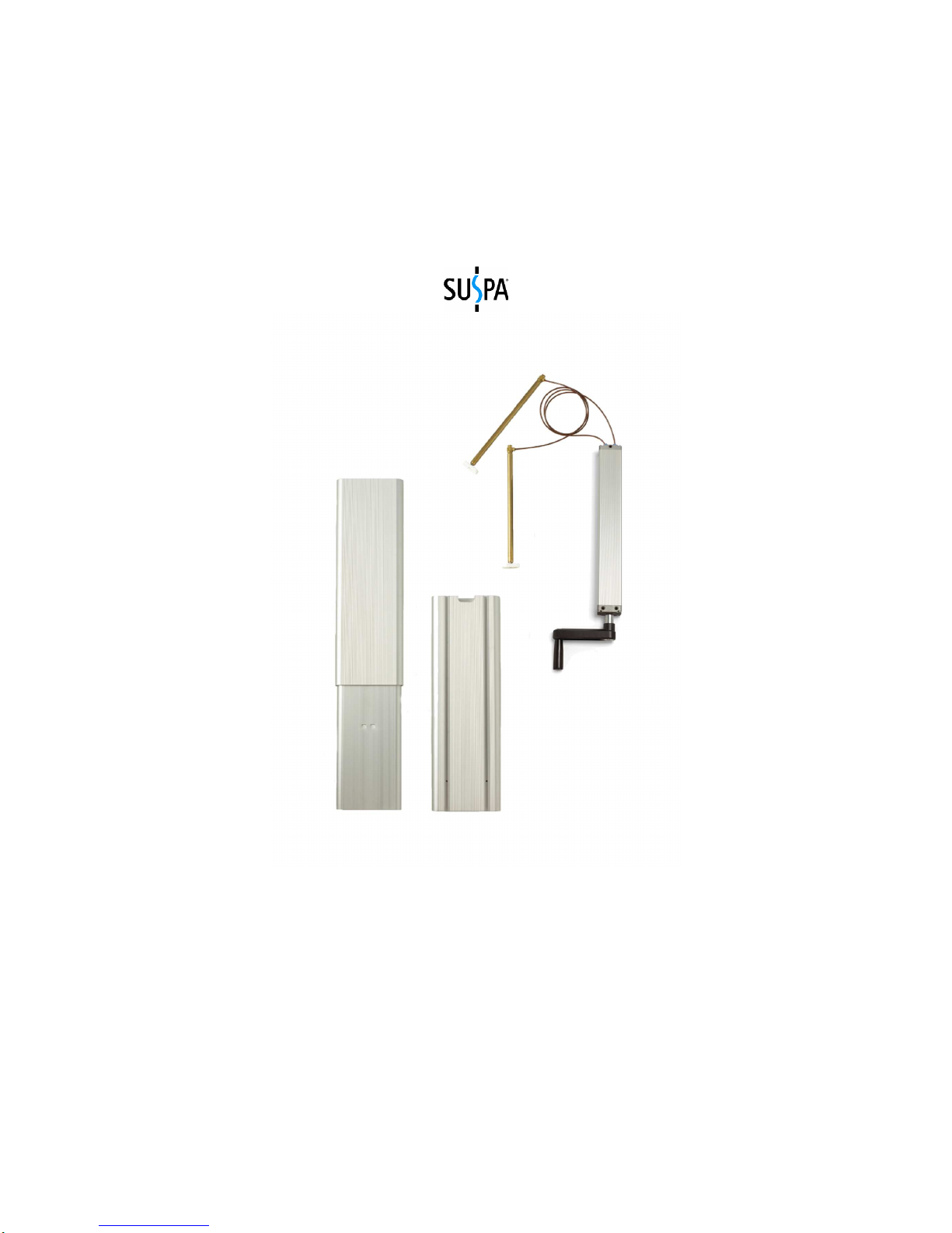
Crank Driven ATU Lift System.
The Movotec
®
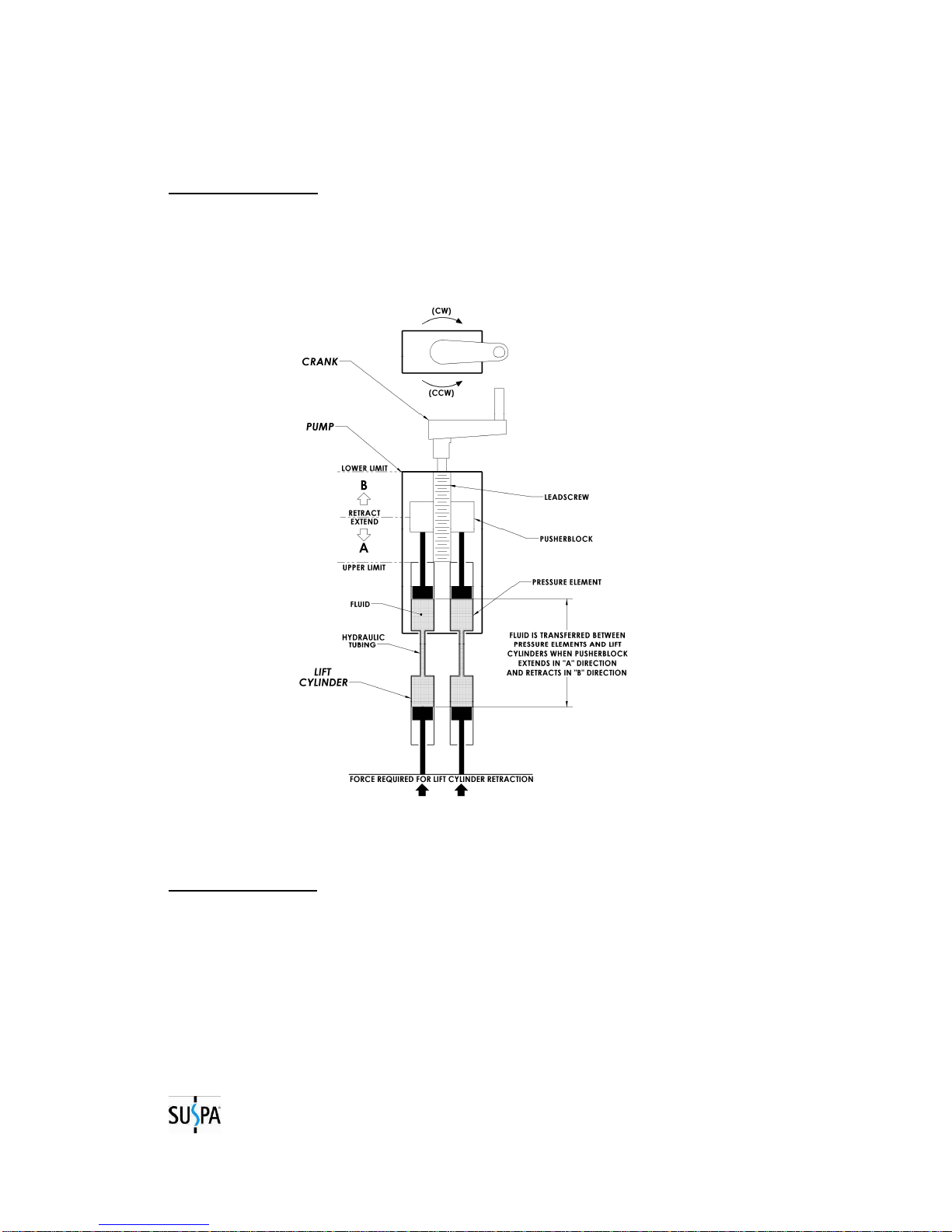
Crank Driven ATU Lift System is a single-acting fluid displacement lift
system that is manually driven by a hand crank. This particular lift system was designed
to be used in conjunction with the Movotec
®
ATU or Aluminum Telescoping Upright.
The Movotec
®
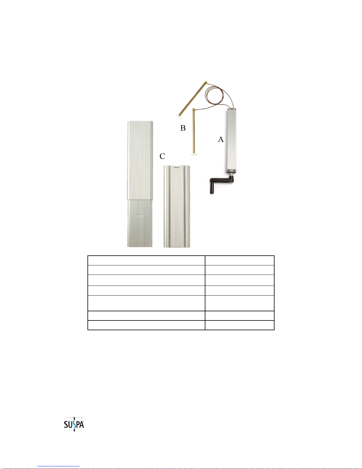
ATU is a telescoping table leg which provides guide support for Movotec
®
lift cylinders throughout their extension and retraction cycle. The ATU also offers a
solution for customers who want to make their own height adjustable table, but do not
have the means to manufacture their own telescoping leg.
Suspa also offers a Movotec
®
ATU Workstation Kit. The workstation kit contains all of
brackets and hardware necessary to construct a complete height adjustable workstation
base and includes everything but the work-surface.
For over twenty years, Movotec
®
systems have been used on industrial workbenches,
small machine bases, physical therapy equipment, massage tables, office furniture,
biological and chemical vented hoods, autopsy and necropsy tables, sewing machine
bases, home healthcare beds, packaging equipment, custom yachts, and many other
applications.
Movotec
®
lift systems are subjected to life cycle testing on a regular basis. The tests are
performed in a temperature and humidity controlled environment under full system load
conditions. Movotec
®
lift systems perform consistently well in this controlled test
environment. However, due to the wide variety of possible lift system applications and
operating conditions, Suspa
®
does not warrant that any particular lift system is suitable
for any specific application. It is the responsibility of the person who specified the
system to determine its “fitness for use” in the application, through testing and analysis,
to ensure safe and reliable performance. A complete statement including terms and
limitations of the Movotec
®
Crank Driven ATU Lift System warranty can be found in
Section 11.0 of this manual.
Movotec
®
lift systems are assembled and subjected to a full function quality test before
they leave our manufacturing facility. Suspa guarantees products are free from material
and manufacturing defects, but cannot support the warranty for our products if they are
altered, misused, misapplied, or abused in any way. It is the responsibility of system
installers, users, and service technicians to read and carry out the instructions in this
manual correctly to prevent these potentially unsafe and unwarranted occurrences from
happening.
Thank you again for purchasing the Movotec
®
Crank Driven ATU Lift System.
Suspa
®
Incorporated