All American CROWLER EL-8000B User manual

2
Table of Contents
Page 3 - Introduction & Getting Started
Page 4 - Parts Diagram
Page 5 - Maintenance
Page 6 - Adjustments & Seam Gauge
Page 7 - Trouble Shooting
Page 8 - Parts Picture List
Page 9 - Parts List
Page 10 - Parts Picture List (Continued)
Page 11 - Parts List (Continued)
Page 12 - Warranty Information

INTRODUCTION
This can sealer was thoroughly inspected and tested at the factory before shipment. Immediately
upon receipt, carefully check the can sealer for damage before using it. Do not operate the can sealer
if it is damaged; call (920)-682-8627 for further instruction.
The EL-8000B comes with the No. 300 Chuck and the S-203B Base Plate. These are designed and set
up to seal a 24oz or 32oz Crowler® can. A sample can was used to set up the machine and was locked
in place during shipping to help protect the machine. (Please note the can might look a little dented.
This will not happen when you have a full can.) Prior to removing the container, lower and raise the
base plate by turning the Can Lifter Handle as far as possible to the left and then back to the right a
few times. Pay attention to the amount of pressure you have to apply to the Lifter Handle when
locking the can into place. It is good to develop a feel for the amount of base plate pressure required
to properly seal a can. Most beer cans have a diameter of 300 (3” diameter) and the No. 300 Chuck
will work. Cans with a bigger or smaller diameter will require a different size Chuck and Base Plate.
Height adjustment with spacers is necessary before attempting to seal other size cans like the 24oz
can.
GETTING STARTED
1. The sealer can be firmly attached to a table or bar using the four bolt holes (cast into sealer
base) to bolt down the sealer. If that isn’t possible, put a bar mat underneath the base of the
machine to prevent any vibration. The weight of the machine will keep it in place.
2. Connect plug to proper receptacle, either 120 or 240 volt depending on your machine.
3. For operation, the seaming lever rivets (CY-22R) should be in the number 2 hole of the cam
roller arms (S-222B). (They come in the number 10 hole for shipping.)
4. Start the motor by switching the cord’s toggle switch to the on position.
5. Lower the Base Plate (S-203B) by turning the Can Lifter Handle (CY-10) as far as possible to the
left.
6. Place lid on filled can and set can on Base Plate (S-203B).
7. Raise can until it is clamped firmly between the Base Plate and Chuck (No. 300) by turning Can
Lifter Handle (CY-10) as far as possible to the right until handle locks itself against the Frame
(S-201). The can is now ready to be sealed.
8. To start operation, push the Reset Lever (No. 90) to the right. The Reset Lever is located on
the right side of the frame. The sealer will make one complete cycle and stop.
9. When sealer is stopped, pull can lifter handle toward you and remove can.

4
PARTS DIAGRAM
Can Lifter Handle
CY-10
Base Plate
S-203B
Sealer Base
S-284X
Electric Motor
S-296
Motor Brace Bracket
87
90
Pulley Wheel Housing
93
Beer Can Chuck
300
Base Plate Shaft
CY-32
Compression Spring
CY-34
Front Gear Cover
CY-65
Reset Lever
90
Chuck Holder Bushing
CY-19
Chuck Holder Bushing
CY-19
Reset Lever
90
Rivet for Cam Roller
CY-22R
Roller Bearing Lever
CY-9S/F
Seaming Roller Pin
CY-18S/F
Seaming Lever
S-208
Adjusting Lever
S-224
Cam Roller Lever
S-222B
Operation Roller
CY-14B/15B
Cam Worm Wheel Cover
CY-2
Lock Screw for Roller Bearing
CY-9LS
Clutch Assembly
92
Adjusting Screw
and Lock Nut
Electric Sealer Frame
S-201X
Seaming Lever Pin
CY-17

5
MAINTENANCE
Quarterly Maintenance Schedule
1. Remove Base Plate and oil Ball Bearing on the underside.
2. Remove Can Lifter Handle and oil brass stem; also oil where Handle comes in contact with Frame.
3. Put fibre grease on all of the teeth of the Cam Worm Wheel located behind the Cam Worm Wheel Cover.
4. Put fibre grease on the teeth of the Bevel Gear located behind the Front Gear Cover.
Daily Maintenance Schedule: Place a few drops of oil at each arrow below.
1
2
4
3
3
2
Oil Roller
Oil Hole in CY-2
Oil Roller
Oil Hole
Oil Hole
Oil Hole

6
ADJUSTMENTS & SEAM GAUGE
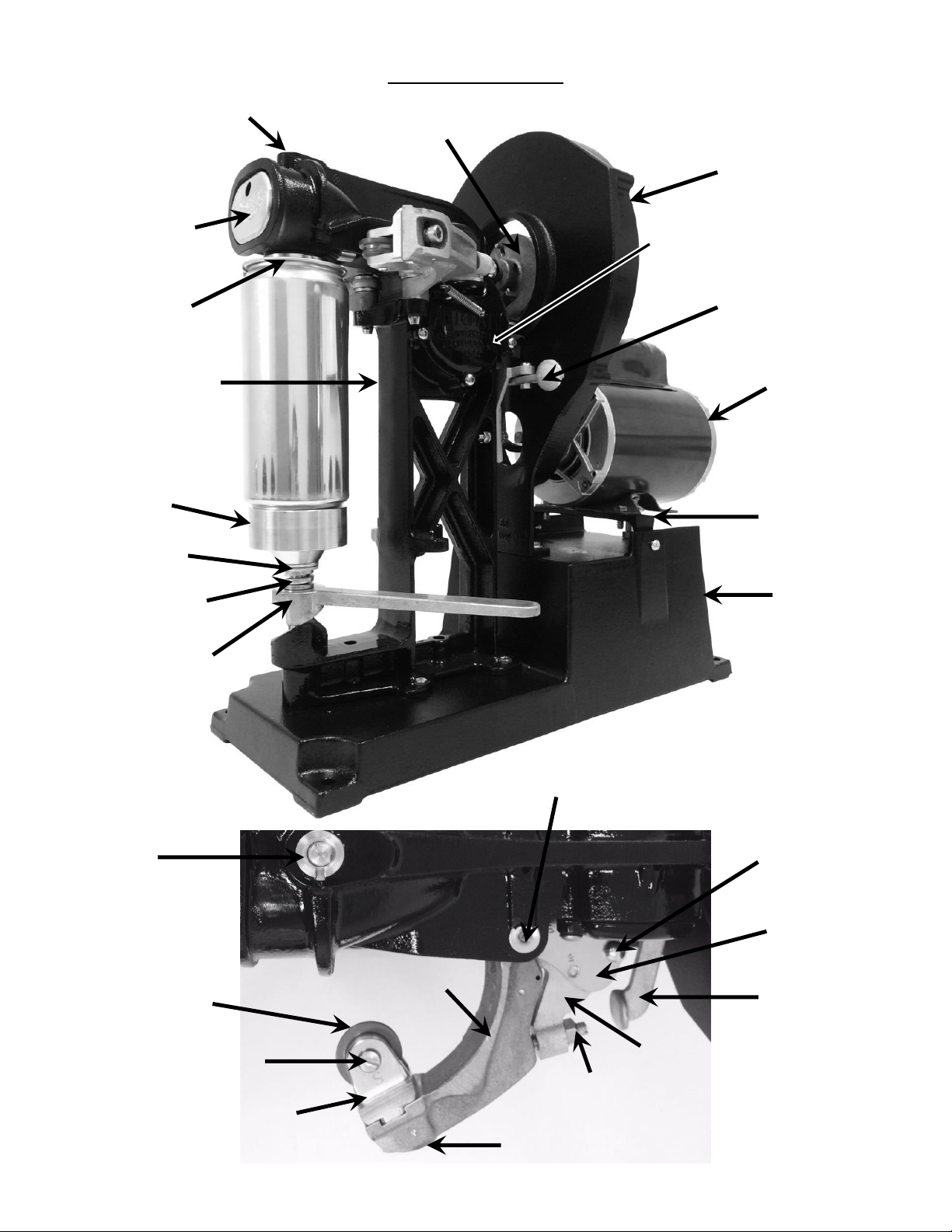
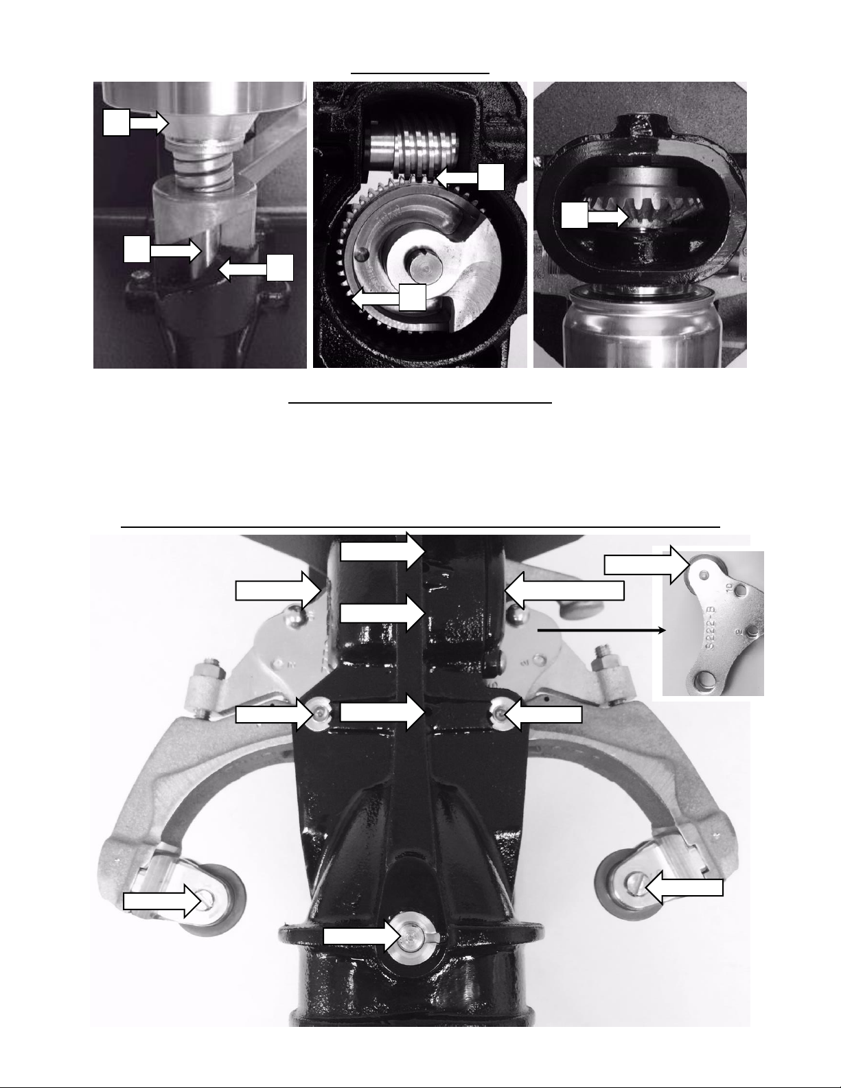
Check the adjustment of the Seaming Rolls occasionally. First
check the height adjustment as follows: When Chuck (A in sketch)
is held up tightly against the Ball Bearing (S-201BB), the underside
of the top flange on the Seaming Roll (B in sketch) must fit closely
on top of Chuck (A). To make adjustments, push the Cam Roller
Lever (S-222B) toward Chuck until Seaming Roll touches the Chuck.
Slightly loosen Screw (CY-9LS) which is “C” in sketch, push down on
Roller Bearing Lever that contains Seaming Roll (B) until top flange
of Seaming Roll (B) rests on top of Chuck (A). Now tighten Screw
(CY-9LS) which is “C” in sketch as tight as possible.
This adjustment should be made on both 1st and 2nd Operation
Rolls. After height adjustment has been made, use the Seam
Gauge which is for checking the seam on 24 or 32oz aluminum beer
cans with a 300 diameter only.
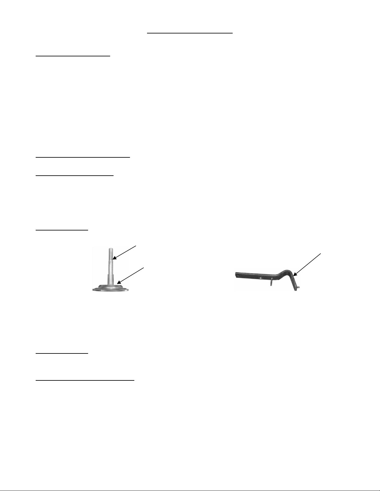
Use the seam gauge as follows: Remove the Rivet (CY-22R) on the Second Operation Cam Roller
Lever (S-222B). The second operation is on the right side if you are facing the front of the machine.
Run an empty can in the machine to seal the First Operation. Remove the can and slip the Gauge
over the seam. The groove marked “1st” should slide over seam on can. The seam will not fill the
entire length of the groove but the Gauge should slip on far enough so that it touches the can cover.
If groove in Gauge will not slip over seam, tighten Seaming Roll (CY-14B) by loosening Lock Nut (No.
24N) and turning Adjusting Screw (No. 24AS) not more than a quarter turn to the right. If the groove
in Gauge is loose on the seam, turn the Adjusting Screw to the left. Repeat above operation with
another empty can until Seam Gauge fits over seam correctly. When first operation seam is correct,
change the Rivet (CY-22R) from the First Operation Levers to the Second Operation Levers and adjust
the Second Operation Roll in the same manner as the First Operation Roll using the can that has a
proper first operation roll seam. The groove in the Seam Gauge marked “2nd” is used when adjusting
the Second Operation Roll (CY-15B). Be sure to tighten the Lock Nuts (No. 24N) after adjusting each
roller.
If it is necessary to operate sealer without a can in place, remove Chuck (No. 300) to prevent
damage to it and Seaming Rolls.

7
TROUBLE SHOOTING
Reasons for Clicking:
1. The No. 92 Clutch Assembly is not riding up on the No. 94 Clutch Knockout far enough.
2. The No. 92 Clutch Assembly is sliding back down the No. 94 Clutch Knockout when the tension
on the can is released to remove the can. This will be the case if the can sealer is very free
running.
3. Lack of sufficient grease under the chuck, on the gears, and oil on parts where the instruction
books shows to oil.
4. Too many height washers on the base plate shaft which results in too much tension on the
can lifter handle. This will cause the unit to run tight.
How to Eliminate Clicking:
Reasons #1 and #2 above:
The No. 94 Clutch Knockout is attached to the No. 99 Bracket which is attached to the CY-1X Frame by
two bolt, lock washer, and nut assemblies. Loosen both assemblies only; do not remove them. Grasp
the No. 90 Reset Lever and decrease the angle of the No. 94 Clutch Knockout by lowering the No. 90
Reset Lever. Always do this in small increments because too low of an angle is not good either.
Reason #3 above:
Remove chuck and apply grease as shown below:
Chuck No. 94 Clutch Knockout
Apply grease to entire shaft of the chuck and also on the whole top of the chuck where the arrow is
pointing in the diagram. Apply grease to the clutch knockout where the arrow is pointing in the
diagram. Also, grease and oil the unit where shown in the instruction book.
Reason #4 above:
Remove 1/16" height washer at a time until you have achieved the proper tension.
Can isn’t spinning properly:
1. Increase belt tension as follows: Loosen lock nut on the tensioning bolt, then turn
tensioning bolt to the right to increase tension. After adjustment, tighten the lock nut.

8
PARTS PICTURE LIST
1
2
6
5
4
3
7
9
8
12
10
14
13
16
17
18
19
20
15
11
21
22
23
30
24
25
26
27
31
29
28
32
34
37
33
36
35
38
39
40
41
44
43
42

9
PARTS LIST
PICTURE NUMBER
1
2
3
4
5
6
7
8
9
10
11
12
13
14
15
16
17
18
19
20
21
22
23
24
25
26
27
28
29
30
31
32
33
34
35
36
37
38
39
40
41
42
43
44
PART NUMBER
88
94
94S
94N
95LLP
90S
90N
90
95
CY-5
S-225X
CY-4
S-206XB
CY-25W
92
CY-7
CY-25D
CY-26
98
S25SS
CY-1E
CY-9LS
CY-9LW
CY-9F
CY-9S
CY-18F
CY-18S
CY-14B
CY-15B
S-208
CY-17
S-222B
CY-22R
S-224
CY24-LN
CY24-AS
CY-35
ES526C1
99
97V
93
85
86
79
DESCRIPTION
Bracket for Clutch Lever (Z0088)
Clutch Knockout (Z00103)
Clutch Knockout Screw
Clutch Knockout Nut
Lever Latch Pin (660525)
Reset Lever Screw
Reset Lever Nut
Reset Lever
Lever Latch (660015)
Bevel Pinion Gear (660890)
Worm Shaft (Z0064)
Bevel Gear w/ Ball Lock (Z000054)
Cam Worm Wheel for Beer Sealer (Z000199)
Worm Shaft Fiber Washer (660860)
Clutch Assembly, Complete (Z000102)
Worm Gear Z00076
Pin for Worm Shaft (660520)
Worm Wheel Shaft (660750)
Pins & Spring Set Only for Clutch Assembly (Z000105)
Flywheel Set Screw (660670)
Escutcheon Pin (660470)
Lock Screw for Roller Bearing (660640)
Lock Washer for Lock Screw (660830)
Roller Bearing Lever –First (Z000056)
Roller Bearing Lever –Second (Z000057)
Seaming Roller Pin –First (660490)
Seaming Roller Pin –Second (660500)
First Operation Roll for Beer Sealer (660605)
Second Operation Roll for Beer Sealer (660615)
Seaming Lever –First or Second (660390)
Seaming Lever Pin (660480)
Cam Roller Lever for Beer Sealer–Complete (660355)
Rivet for Cam Roller & Adjusting Levers (660580)
One (1) Adjusting Lever - Works for First or Second (Z0063)
Lock Nuts (2) for Adjusting Screw (660440)
Adjusting Screw for Adjusting Levers (660580)
Seaming Lever Spring (Z000169)
Shaft Collar (660530)
Set of Pin, Nut & Washer for Pulley Wheel (Z000104)
V Belt (660560)
Pulley Wheel (Z0093) May need to order part #99 also
Pulley Housing (Z0085)
Pulley Housing Cover (Z0086)
Cover Screw

10
PARTS PICTURE LIST
45
50
51
52
53
55
46
46
49
58
57
59
66
69
65
64
63
62
67
68
61
60
47
48
56
54

11
PARTS LIST
PICTURE NUMBER
45
46
47
48
49
50
51
52
53
54
55
56
57
58
59
60
61
62
63
64
65
66
67
68
69
PART NUMBER
S-284X
670040
670035
84S
84N
87A
87B
CY-24LN
89LS
89N
89
79
97P5
S-296-2-6
CY-10
300
CY-65
CY-34
1/8” HW
S-203B
CY-32
CY-2
CY-2S
CY-19
S-201X
DESCRIPTION
Senior Electric Base
¼” x 20 x ¾” Hex Bolt
Washer for Pulley Housing
Tension Bolt (670100)
Lock Nut (670090)
Motor Brace Bracket (Z00186)
Bolt for Motor Bracket (670080)
Lock Nut for CY-24 (660440)
10-24 x 7/8”89 Connector (670110)
Nut for 89 Connector (670120)
Guard Brace (Z0089)
Guard Brace Screw
5/8”x 2” Pulley (660550)
Electric Motor, Specify for 240V (660410)
Can Lifter Handle (660250)
Beer Can Chuck (660215)
Front Gear Cover (660910)
Base Plate Compression Spring (660760)
1/8” Height Washer (660820)
Base Plate w/ Ball Bearing for Beer Sealer (660025)
Base Plate Shaft (660700)
Cam Worm Wheel Cover (Z000074)
Cover Plate Screw (670010)
Chuck Holder Bushing (Top) (660070)
Electric Sealer Frame (Z0091)

12
ALL AMERICAN
AUTOMATIC MASTER CAN SEALER
LIMITED WARRANTY
This quality Automatic Master Can Sealer is designed and manufactured to provide many years of
satisfactory performance under normal use. Wisconsin Aluminum Foundry guarantees to the original
owner that should there be any defects in material or workmanship during the first ninety (90) days
after purchase, we will repair or replace it, at our option. This warranty does not apply to damage
caused by shipping. To obtain service under the warranty, please do the following:
1) Call the Customer Service Department to obtain a Return Authorization (RA) Number.
Items returned without a Return Authorization Number will be refused.
2) Return can sealer, shipping prepaid with sales receipt, RA Number and a description of the
claimed defect to:
WISCONSIN ALUMINUM FOUNDRY CO., INC.
CONSUMER PRODUCTS DIVISION
1931 South 14th Street / PO Box 246
MANITOWOC, WI 54220
Return transportation will be prepaid on all can sealers under warranty. Repairs made after the
warranty has expired will be billed at the current repair costs.
We want you to obtain maximum enjoyment from using this quality can sealer and we ask that you
take the time to read and follow the operating instructions. Failure to follow instructions, damage
caused by improper replacement parts, abuse, or misuse will void this warranty.
This warranty gives you specific legal rights, and you may also have other rights which vary from state
to state. This is Wisconsin Aluminum Foundry’s guarantee to you and is being made in place of all
other express warranties.
Important - please read: Any alterations, modifications or changes of any type
made to the can sealer or to any component thereof will void this warranty.
WISCONSIN ALUMINUM FOUNDRY CO., INC.
P.O. BOX 246 MANITOWOC, WI 54221-0246
PHONE: 920-682-8627 FAX: 920-682-4090
Table of contents
Other All American Food Saver manuals