All Seasons Hire Red Star User manual

Instruction Manual
Red
Star
Mobile Direct Fired Diesel Heater
Hanging Indirect Fired Diesel Heater
Mobile Indirect Fired Diesel Heater

Disclaimer
We reserve the right to make alterations to specifications, quantities, dimensions etc. for
production or other reasons, subsequent to publication.
The information contained herein has been prepared by qualified experts.
While we believe the information is accurate and complete, we make no warranty or
representation for any particular purposes. The information is offered in good faith and with the
understanding that any use of the units or accessories in breach of the directions and warnings in
this document is at the sole discretion and risk of the user.


• It is forbidden to connect direct-fired heaters to air ducts.
Maintenance and checks
• Depending on the operational conditions, usually every year,
the heater should be checked by qualified personnel.
• Prior to start-up, the user must check for any evident non-
compliance with rules of use, safety and protection.
4. INSTRUCTIONS FOR USE
4.1 Start-up
• The heater is factory set for operation without room thermo-
stat.
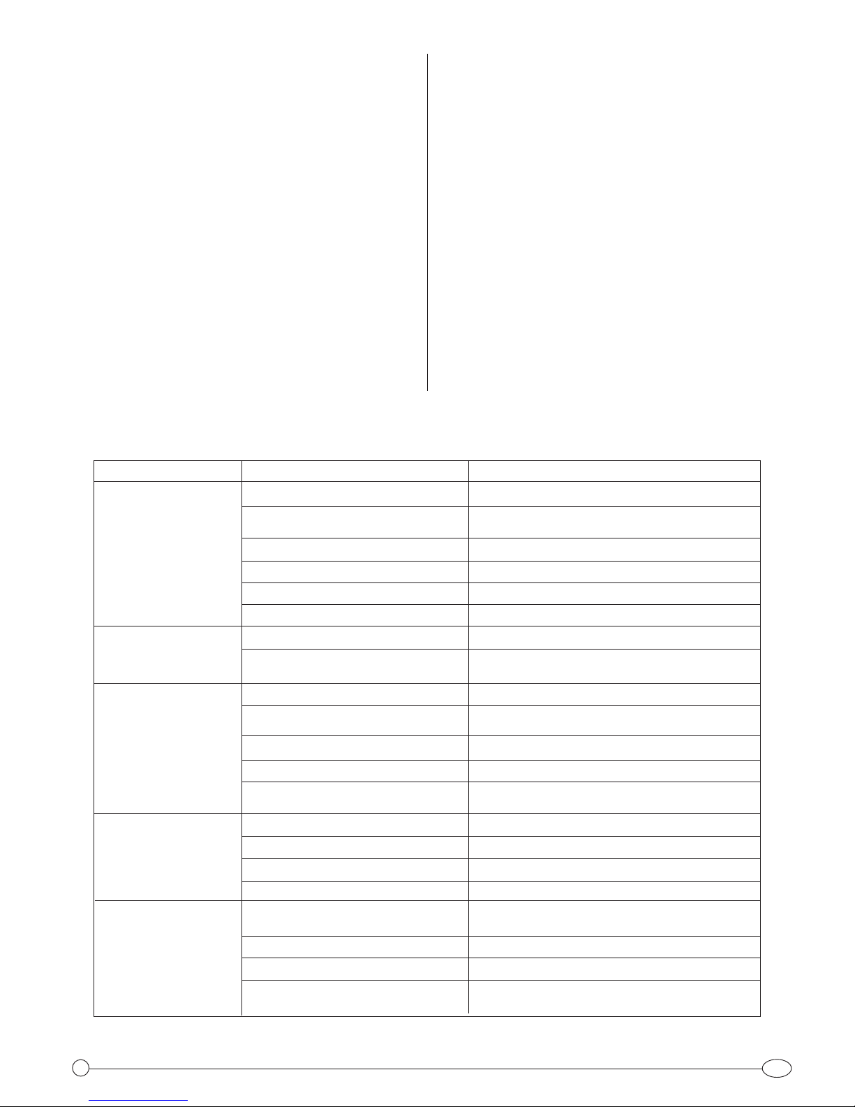
• If operation with room (remote) thermostat is desired, remove
the socket cover (Fig. 1 nr. 1) and insert the thermostat plug
into the socket.
• Fill the tank with proper fuel.
• Connect the supply plug to a 230V ~ 50 Hz single-phase
earthed socket. The green lamp indicates that the heater is
powered.
• WARNING: THE APPLIANCE MUST BE EARTHED
• Indirect fired heaters: connect the heater to a chimney or to
a exhaust duct. To get a proper draught (at least 0,1 mbar)
in the chimney the exhaust gas path must rise. Avoid any
elbows and bends in the first part of the exhaust ducts for
at least 3 m. For operation of heater in closed rooms without
flue refer to the instructions for installation (par. 4)
• If a room thermostat is used, set maximum temperature on
it.
• Turn switch to position “ON”
• Set the desired temperature on room thermostat.
1. GENERAL SAFETY RULES
• READ THE INSTRUCTIONS GIVEN IN THIS MANUAL BE-
FORE USING THE APPLIANCE.
• THE ELECTRICAL SYSTEM TO WHICH THE APPLIANCE IS
CONNECTED MUST COMPLY WITH ALL SAFETY REGULATIONS
IN FORCE. A RESIDUAL CURRENT CIRCUIT BREAKER MUST BE
PROVIDED ON THE MAIN DISTRIBUTION BOARD.
• UNPLUG THE HEATER BEFORE ATTEMPTING ANY SERVICE OR
MAINTENANCE.
• ALWAYS CHECK THE POWER SUPPLY CABLE BEFORE USE. IT
MUST NOT BE BENT, CRUSHED, OR ANYWAY DAMAGED.
• THE POWER SUPPLY CABLE MUST BE REPLACED ONLY BY QUA-
LIFIED PERSONNEL.
• ONLY USE AN ORIGINAL H07RN-F POWER CABLE WITH WATER-
PROOF PLUG.
• DO NOT TOUCH THE EXHAUST GAS OUTLET. DANGER OF
BURNS!
• THE HEATER IS INTENDED FOR PROFESSIONAL USE ONLY.
2. APPLIANCE DESCRIPTION
• Mobile space heater with:
- closed combustion chamber and gas exhaust duct (indirect-
fired models)
- open combustion chamber (direct-fired models)
3. INSTALLATION INSTRUCTIONS
3.1. General instructions
• The heater must be operated only by properly trained per-
sonnel. The manufacturer’s instructions must be followed.
• The heater must be installed and operated so that people are
not exposed to dangers deriving from exhaust gases, from
the hot air flow and in such a way that no fire risks exist.
• It is forbidden to install the heater in the surroundings of
flammable materials, combustible products, or in places
where explosion risk exist.
• When an indirect-fired heater is used in a closed room,
ensure a minimum volume of 10 m3/ kW power input and
a continuous natural air circulation through windows and
doors. For a good combustion, provide at least 80
m3/h air flow from outside.
• When a direct-fired heater is used in a closed room, ensure a
minimum volume of 31 m3/ kW power input and a conti-
nuous natural air circulation through windows and doors.
Moreover 2,5 hourly air exchanges based on the total room
volume must be supplied. To get this, two openings, one at
floor level and one at ceiling level, must be provided each
with a free area of 0.01 m2/ KW power input.
• If the levels of harmful substances are within the standard
limits and the O2content equals at least 17% no health risks
exist in the working areas.
• For the use of the heater the general and special fire safety
regulations in force in all fields of applications must be fol-
lowed. In any case the following minimum safety clearances
from materials or objects in the surroundings of the heater
must be ensured:
Sides: 0,60 m Air inlet: 0,60 m
Top: 1,50 m Air outlet: 3,00 m
• Floors and ceilings must be made of fireproof materials in the
room where the heater is operated.
• The air inlet and outlet must never be blocked for any rea-
son.
• Install the heater on a flat, level floor in a steady position.
GB 1
1 2 3 4
Fig. 1

GB
2
TROUBLE
Heater does not start
Heater starts, flame ignites
but then heater locks out
Heater starts, flame does
not ignite and then heater
locks out
Heater starts, but combu-
stion is not good
Heater stops due to safety
thermostat
CAUSE
No power
Faulty cable/connections
Burnt fuse
Room thermostat set too low
Thermostat socket cap not inserted
The safety thermostat has been activated
Dirty or faulty flame sensor
Faulty burner control unit
Clogged nozzle
Flame sensor receives an external light
signal during ignition sequence
Faulty burner control unit
No fuel
Ignition fault, dirty or incorrectly
spaced electrodes
Dirty or blocked nozzle
Clogged filters
Leakes in fuel circuit
Oil pump provides low pressure
Insufficient combustion air
Insufficient ventilation air
The appliance has overheated
Faulty safety thermostat
SOLUTION
Check main distribution board and power supply line
Check/have cable replaced by a
qualified electrician
Check and replace if required
Set room thermostat on a higher temperature
Insert cap into the thermostat socket
Reset the safety thermostat
Clean or replace
Contact service personnel
Clean or replace
Check for external lights (sun, lamps, etc.)
Contact service personnel
Fill tank
Clean electrodes, contact service personnel if
required
Clean or replace
Clean or replace
Check and eventually replace
Contact service personnel
Pulire la fotocellula e, se questo non basta,
rivolgersi a personale specializzato
Wrong air lock setting
Contact service personnel
6. TROUBLESHOOTING
Never disconnect the supply plug to stop the heater
while in operation
The big amount of heat produced could damage the
components or activate the safety thermostat and
therefore make the unit not function
5. MAINTENANCE
• Before carrying out any maintenance operation, disconnect
the power plug.
• Maintenance must be carried out by qualified personnel (see
also par. 7)
• The appliance must be thoroughly cleaned once a year to
ensure good combustion and long life.
• Clean periodically
the oil spraying nozzle and its filter;
the oil pump filter
the main fuel filter cartridge
the ignition electrodes
the fan blades
the inside of the appliance, using compressed air
the flame sensor with a mild detergent
• Periodically check cables and electrical connections
• Check the oil filter and replace if necessary.
WARNING!
Heaters equipped with heated nozzle do not start im-
mediately or may stop for some seconds after start.
This is normal and should not be considered a faulty
condition.
4.2. Reset after lockout and Reset of safety thermostat
• The heater is equipped with a Reset pushbutton. When the
heater locks out, the red lamp on the pushbutton (fig. 1 n°2)
lights up. In this case push the Reset button (see also the par.
“Troubleshooting”) to restart the heater.
• The heater is also equipped with a manual reset safety ther-
mostat fixed to the combustion chamber, that can be rea-
ched through the inspection cover. To reset the thermostat:
unplug the heater, open the inspection cover and push the
reset button on the thermostat body.
4.3. Shut down.
• Set switch to “OFF” to shut the flame off. The fan will go on
rotating for about 1’45’’ to cool the heater down. The fan
motor will automatically stop at the end of the aftercooling
time, then the unit can be disconnected from mains.

DE 3
• Die Ansaug- und Ausblasöffnungen des Warmlufterzeugers dür-
fen auf keinen Fall, auch nicht nur teilweise, abgedeckt werden.
• Das Gerät muss standfest aufgestellt werden.
• Bei den Geräten ohne Kamin ist es verboten, diese an Schläuchen
oder an Kanalisierungen zwecks Luftleitung anzuschließen.
Wartung und Kontrollen
• Das Gerät sollte unter Zugrundelegung der Arbeitsbedingungen,
im Durchschnitt mindestens einmal jährlich, von einem
Fachmann überprüft werden.
• Die mit der Bedienung des Gerätes beauftragten Personen müs-
sen vor Inbetriebnahme sicherstellen, dass keine augenfällige
Nichtbeachtung der Bedienungsanleitung, der Sicherheits- und
Schutzvorschriften vorliegt.
4. BETRIEBSANLEITUNG
4.1 Inbetriebnahme
• Das Gerät ist für den Betrieb ohne Raumthermostat bestimmt.
• Für den Einsatz des Gerätes mit Raumthermostat den
Blindstecker der Thermostatsteckdose (Abb. 1 Nr. 1) entfernen
und den Stecker des Thermostats in die dazugehörige Steckdose
einstecken.
• Sauberes Heizöl in den Öltank des Gerätes einfüllen.
• Stecker in eine geerdete Einphasenstrom-Steckdose 230 V - 50
Hz stecken. Die grüne Kontrollleuchte (Abb. 1 Nr. 4) zeigt die
Betriebsbereitschaft des Gerätes an.
• Die vorschriftsmäßige Erdung ist Pflicht.
• Das Gerät mit Kamin an einen ggf. vorhandenen Kamin anschließen
oder die Abgase mittels Rauchgasrohren ins Freie ableiten. Um
einen Zug von mindestens 0,1 mb in der Abgasleitung zu errei-
chen, ist darauf zu achten, dass die Abgasführung steigend
verlegt wird. In den ersten drei Metern der Abgasleitung dürfen
keine Knie oder Bögen vorhanden sein. Bei Einsatz des Gerätes in
geschlossenen Räumen ohne Kamin sind die Aufstellrichtlinien
in § 4 zu beachten.
• Wird ein Raumthermostat angeschlossen, muss es auf die maxi-
mal mögliche Temperatur eingestellt werden.
• Schalter (Abb. 1 Nr. 3) auf “ON” stellen.
• Das Thermostat auf die gewünschte Temperatur einstellen.
Nicht mehrere Geräte an ein und dasselbe Raumthermostat
anschließen.
1. ALLGEMEINE SICHERHEITSHINWEISE
• BENUTZEN SIE DAS GERÄT NICHT, OHNE VORHER DIE
VORLIEGENDE BETRIEBSANLEITUNG GELESEN ZU HABEN.
• Die elektrische Anlage, an die das Gerät angeschlossen ist, muss
in Übereinstimmung mit den
geltenden Gesetzen ausgeführt werden. Stromaufwärts zur
Steckdose sollte ein magnetothermischer Differentialschalter
vorhanden sein.
• Vor allen Wartungsarbeiten den Netzstecker aus der Steckdose
ziehen.
• Vor Benutzung des Gerätes das Anschlusskabel auf Beschädigung
prüfen. Das Kabel darf nicht
geknickt, gedehnt, gequetscht oder sonst wie beschädigt sein.
• Das Anschlusskabel darf nur von Elektrofachleuten ausgetauscht
werden.
• Nur Kabel vom Typ H07RN-F mit spritzwassergeschütztem
Stecker verwenden.
• Die Abgasrohre nicht berühren. Verbrennungsgefahr!
• Die Geräte dürfen nur zu gewerblichen Zwecken eingesetzt
werden.
2. GERÄTEKURZBESCHREIBUNG
• Ortveränderlicher, ölbefeuerter Warmlufterzeuger mit:
- geschlossener Brennkammer und Anschlussstück für einen Kamin
zur Abgasabführung bei den Modellen mit Kamin
- offener Brennkammer bei den Modellen ohne Kamin.
3. AUFSTELLRICHTLINIEN
3.1. Allgemeine Hinweise
• Das Gerät darf nur von dafür geschultem Personal in Betrieb
genommen werden. Es müssen dabei die vom Hersteller gelie-
ferten Betriebsanleitungen befolgt werden.
• Das Gerät muss so installiert werden, dass das Personal weder
durch die Abgase noch durch den Warmluftstrom in Gefahr
gebracht wird, und auch so, dass keinerlei Brandgefahr besteht
• Das Gerät darf nicht in der Nähe von brennbaren Materialien,
Brennstoffen oder an feuer- oder explosions- gefährdeten Orten
aufgestellt werden.
• Bei Aufstellung des Gerätes mit Kamin in geschlossenen Räumen
muss der Raum ein Mindestvolumen von 10 m3pro kW der
installierten Nennheizleistung aufweisen; es muss jedenfalls
eine andauernde und natürliche Frischluftzufuhr durch Türen
und Fenster hindurch sichergestellt werden. Besonders muss,
um eine gute Verbrennung zu erhalten, darauf geachtet werden,
dass ein Frischluftvolumen von mehr als 80 m3/h von Außen
garantiert wird.
• Sollte ein Gerät ohne Kamin in geschlossenen Räumen in Betrieb
genommen werden, muss der Raum ein Mindestvolumen von
31 m3pro kW der installierten Nennheizleistung aufweisen; es
muss jedenfalls eine andauernde und natürliche Frischluftzufuhr
durch Türen und Fenster hindurch sichergestellt werden.
Darüber hinaus muss ein Luftaustausch gewährleistet werden,
der 2,5 mal das Volumen des Raumes pro Stunde beträgt. Um das
zu erreichen, muss nötigenfalls eine Öffnung auf Fußbodenhöhe
und eine auf Deckenhöhe, die jede eine freie Oberfläche von
0,01 m2pro kW der installierten Nennheizleistung haben muss,
zur Frischluftzufuhr angebracht werden.
• Wenn die maximalen Konzentrationswerte der giftigen
Substanzen im Arbeitsbereich sich in den grenzen der Normen
befinden, und der Prozentsatz von O2gleich oder größer als 17%
ist, bestehen keine Gefahren für die Gesundheit, die bei einer zu
hohen Konzentration von giftigen Substanzen in der eingeatme-
ten Luft beständen.
• Bei Einsatz des Gerätes müssen die in den jeweiligen Bereichen
geltenden
Feuerschutz-Sicherheitsvorschriften eingehalten werden. Es
müssen jedenfalls die folgenden Sicherheitsabstände von brenn-
baren Materialien oder Komponenten befolgt werden:
Seitlich: 0,60 m Luftansaugseite: 0,60 m
Oben: 1,50 m Ausblasseite Warmluft: 3,00 m
• Im Aufstellungsraum müssen Decke und Fußboden aus
feuerbeständigen Materialien bestehen und den geltenden
Feuerschutzrichtlinien entsprechen.
1 2 3 4
Fig. 1

DE
4
STÖRUNG
Gerät springt nicht an
Gerät läuft an, Flamme
zündet, Gerät geht
jedoch auf Störung
Gerät läuft an,
Flamme zündet nicht
und Gerät geht auf
Störung
Gerät läuft an,
aber Verbrennung
ist nicht zufrieden-
stellend
Gerät schaltet ab, da
Sicherheitsther-mostat
eingreift
URSACHE
Kein Strom
Kabel beschädigt oder Sicherung durchgebrannt
Raumthermostat zu niedrig eingestellt
Blindstecker nicht eingesteckt
Sicherheitsthermostat hat Gerät ausgeschaltet
Fotowiderstand verschmutzt oder defekt
Flammenkontrollkarte defekt
Brennerdüse verstopft
Fotowiderstand von Außenlichtquelle
gestört (Fremdlicht)
Flammenkontrollkarte defekt
Heizöl fehlt
Zündeinrichtung defekt oder Elektroden verbogen,
verschmutzt oder beschädigt
Brennerdüse verschmutzt oder teilweise verstopft
Heizölfilter verstopft
Ölleitungen undicht
Ölpumpe bringt zu wenig Druck
Es fehlt Luft für dieVerbrennung
Defekte Lüftung
Überhitzung des Warmlufterzeugers
Sicherheitsthermostat defekt
BESEITIGUNG
Netzschalter und Zuleitung überprüfen
Von einem Fachmann auswechseln lassen
Thermostat auf höhere Temperatur einstellen
Blindstecker einstecken
Durch Drücken auf den Knopf Sicherheitsthermostat
entriegeln
Reinigen oder ersetzen
Fachleute hinzuziehen
Reinigen oder ersetzen
Kontrollieren
Fachleute hinzuziehen
Tank nachfüllen
Reinigen oder sich an einen Fachmann wenden
Reinigen oder auswechseln
Ölleitungen überprüfen und gegebenenfalls
auswechseln
Defekt vom Fachmann beseitigen lassen
Sich vergewissern, dass die Stauscheibe korrekt
eingestellt ist.Kontrollieren, dass die vorgeschriebenen
Lüftungsverhältnisse im Raum eingehalten werden
Sich an einen Fachmann wenden
Fachleute hinzuziehen
6. BETRIEBSSTÖRUNGEN
Netzsteckers ausschalten.
• Die große Menge restlicher Wärme könnte das Gerät beschädigen
oder jedenfalls das Sicherheitsthermostat betätigen, so dass das
Gerät außer Betrieb gesetzt wird.
5. WARTUNG
• Wartungsarbeiten nur bei herausgezogenem Netzstecker vor-
nehmen.
• Die Wartung muss von Fachleuten durchgeführt werden (siehe
auch §7).
• Einmal jährlich muss das Gerät vollständig überprüft und gerei-
nigt werden, um eine einwandfreie Verbrennung und eine lange
Lebensdauer sicherzustellen.
• In regelmäßigen Abständen zu reinigen sind:
die Öleinspritzdüse und den dazugehörigen Filter;
der Filter der Heizölpumpe
der Filtereinsatz des Öltanks;
die Elektroden;
die Ventilatorflügel;
das Geräteinnere (Druckluft verwenden);
der Fotowiderstand mit Äthylalkohol.
• In regelmäßigen Abständen den Zustand der Kabel und der
Elektroanschlüsse überprüfen.
• In regelmäßigen Abständen den Zustand des Ölfilters überprüfen
und nötigenfalls auswechseln.
ACHTUNG!
Es ist normal, dass Geräte mit beheizter Düse nicht
sofort anspringen und während der anfänglichen
Zündvorgänge einige Augenblicke stehen bleiben; das
bedeutet jedoch nicht, dass das Gerät defekt ist.
4.2. Manuelle und
Sicherheits-Inbetriebnahme
• Das Gerät verfügt über einen Leuchtschalter zur manuellen
Inbetriebnahme. Geht das Gerät auf Störung, schaltet sich die
rote Kontrollleuchte (Abb. 1 Nr. 2) ein. In diesem Falle den RESET-
Knopf drücken, um das Gerät wieder anzufahren
(siehe auch unter Punkt „Problemlösung“)
• Das Gerät ist auch mit einem Sicherheitsthermostat mit manueller
Inbetriebnahme ausgerüstet, das sich an der Brennkammer befin-
det und durch die obere Kontrollklappe erreichbar ist. Sollte das
obige Sicherheitsthermostat ansprechen, muss der Netzstecker
gezogen werden; erst danach wird die Kontrollklappe geöffnet
und auf den zentralen Knopf des Thermostates gedrückt.
4.3. Außerbetriebnahme.
• Den Schalter in die Position “OFF” bringen und somit die Flamme
ausmachen. Der Lüfter bleibt noch für ca. 1’45“ in Betrieb, um den
Warmlufterzeuger zu kühlen: das Gerät schaltet sich automatisch
ab, wenn die Zeit zu Ende geht, die auf der Karte eingegeben ist.
Danach kann der Netzstecker gezogen werden.
• Den Warmluferzeuger niemals durch Herausziehen des

FR 5
l’appareil doit être contrôlé par des Techniciens spécialisés.
• Les personnes responsables de l’emploi de l’appareil doivent con-
trôler avant sa mise en service qu’il n’y a aucune inobservation
évidente des règles d’utilisation, de sécurité et de protection.
4. MODE D’EMPLOI
4.1 Mise en route
• L’appareil est conçu pour le fonctionnement sans thermostat
d’ambiance. Pour le fonctionnement de l’appareil avec un ther-
mostat d’ambiance, il faut retirer le capuchon de protection de
la prise thermostatique (fig.1 N°1) et le remplacer par la fiche
correspondante du thermostat câblé.
• Remplir le réservoir de l’appareil avec du fuel propre. Brancher la
prise d’alimentation à une prise de courant 230V ~ 50 Hz
monophasée + Terre. La lampe verte (fig.1 N°4) éclairée indique
que l’appareil est sous tension.
• La mise à la terre est obligatoire selon les normes en vigueur.Si
il y a lieu, raccorder l’appareil à une cheminée ou à un conduit
pour la sortie des fumées vers l’extérieur. Pour obtenir un tirage
d’au moins 0,1 mmbar dans le conduit, il est nécessaire que le
parcours des fumées soit ascendant. De plus, il faut éviter la
présence de coudes dans la première partie du tubage sur un
minimum de 3 m. Pour un fonctionnement de l’appareil dans des
locaux fermés sans cheminée, consulter les instructions pour
l’installation (§ 4).
• Si le thermostat d’ambiance est raccordé, le régler sur la tem-
pérature maximum
• Placer l’interrupteur (fig. 1 N°3) sur la position “ON”.
• Régler le thermostat sur la température désirée.
• Modèles avec cheminée: raccorder l’appareil à une cheminée ou à
un conduit pour la sortie des fumées vers l’extérieur. Pour obtenir
un tirage d’au moins 0,1 mbar dans le conduit il est nécessaire
que le parcours des fumées soit ascendant. De plus, il faut éviter
la présence de coudes dans la première partie du tubage sur un
minimum de 3 m. Pour le fonctionnement de l’appareil dans des
locaux fermés sans cheminée, consulter les instructions pour
l’installation (§ 4).
• Si le thermostat d’ambiance est raccordé, le régler sur la tem-
pérature maximum.
Placer l’interrupteur (fig. 1 N°3) sur la position “ON”.
• Régler le thermostat sur la température désirée
• Ne pas brancher plusieurs appareils sur le même thermostat.
1. NORMES GENERALES DE SECURITE
• NE PAS UTILISER L’APPAREIL SANS AVOIR LU LES
INSTRUCTIONS CONTENUES DANS CETTE NOTICE.
• L’installation électrique à laquelle est raccordé l’appareil devra
être réalisée suivant la règlementation en vigueur. Nous recom-
mandons de prévoir un disjoncteur différentiel en amont de la
prise d’alimentation.
• Avant d’effectuer toute opération d’entretien il faut débrancher
l’appareil.
• Avant d’utiliser l’appareil, vérifier l’état du câble d’alimentation.
Celui-ci ne doit être ni plié, ni tendu, ni écrasé et de toute façon
ne doit être endommagé d’aucune manière.
• Le câble d’alimentation ne doit être remplacé que par du
Personnel agréé.
• Il faut utiliser uniquement un câble du type H07RN-F avec prise
protégée contre les projections d’eau.
• Ne pas toucher le conduit de sortie des gaz de combustion;
risque de brûlures !
• L’appareil ne doit être employé qu’uniquement dans le cadre
d’une utilisation professionnelle.
2. DESCRIPTION DE L’APPAREIL
• Générateur d’air chaud mobile à fuel avec
- chambre de combustion fermée et conduit de raccordement à une
cheminée pour la sortie des fumées (modèles avec cheminée).
- chambre de combustion ouverte (modèles sans cheminée)
3. INSTRUCTIONS POUR L’INSTALLATION
3.1. Instructions générales
• L’appareil ne doit être employé qu’uniquement par du Personnel
préalablement formé à son utilisation. Il est impératif de res-
pecter les instructions fournies par le constructeur.
• L’appareil doit être installé de manière à ce que le Personnel ne
soit pas exposé aux risques provoqués par les gaz de combu-
stion ou par la sortie d’air chaud, et de façon à ce qu’il n’y ait pas
de risque d’incendie.
• Il est interdit d’installer l’appareil à proximité de matières inflam-
mables ou dans des locaux comportant des risques d’incendie
ou d’explosion.
• Si l’appareil avec cheminée est employé dans des locaux fermés,
le local doit avoir un volume minimal de 10 m3par kW de puis-
sance utilisé et pour assurer une bonne combustion, un apport
constant d’air neuf de 80 m3/h.
• Si l’appareil sans cheminée est employé dans des locaux fermés,
le local doit avoir un volume minimum de 31 m3par kW de puis-
sance utilisé et il faut assurer une circulation constante d’air neuf
correspondant à 2,5 fois le volume du local. Pour obtenir cela il
faut prévoir si nécessaire, une ouverture basse pour l’entrée de
l’air et une ouverture haute pour la sortie de l’air, chacune de ces
ouvertures devant avoir une surface libre d’au moins 0,01 m2par
kW de puissance utilisé.
• Si les valeurs de concentration maximum des éléments toxiques
dans le local de travail restent dans les limites prévues et que le
pourcentage de O2est égal ou supérieur à 17%, il n’y aura aucun
risque sanitaire qui serait consécutif à une concentration exces-
sive d’éléments toxiques dans l’air inspiré.
• Pour l’emploi de ces appareils dans les domaines du bâtiment
et de l’agriculture il faut respecter les mesures de sécurité en
vigueur dans chacun de ces secteurs. Il faut notamment respecter
les distances de sécurité suivantes par rapport aux matériaux ou
aux matières inflammables:
Latérale: 0,60 m Côté entrée air: 0,60 m
Au-dessus : 1,50 m Côté sortie air chaud: 3,00 m
Dans le local où est installé l’appareil, le sol et le plafond doivent
être réalisés avec des matériaux ignifuges conformes aux règles
de protection contre les incendies.
• Les sections d’entrée et de sortie de l’air ne doivent jamais être
bouchées, même partiellement et ce pour aucune raison.
• L’appareil doit être installé en position stable.
• Le raccordement des appareil sans cheminée à des gaines de
soufflage est interdit.
Maintenance et contrôles
• Suivant les conditions d’utilisation et une fois par an minimum,
1 2 3 4
Fig. 1

FR
6
L’excès de chaleur résultant pourrait endommager les com-
posants électriques et dans
tous les cas, activer le thermostat de sécurité.
5. MAINTENANCE.
• Ne pas effectuer de travaux d’entretien sans avoir préalablement
débranché la prise d’alimentation électrique.
• L’entretien doit être effectué seulement par des Techniciens
agréés (voir aussi §7).
• Une fois par an, l’appareil doit être entièrement nettoyé afin d’as-
surer un fonctionnement de qualité sur une longue durée.
Nettoyer périodiquement:
le gicleur ainsi que le filtre fuel.
le filtre de la pompe à fuel.
le préfiltre au remplissage du réservoir.
les électrodes et leur positionnement.
les pales du ventilateur.
l’intérieur de l’appareil en soufflant de l’air comprimé.
la cellule photoélectrique en utilisant de l’alcool étylique.
• Contrôler périodiquement l’état des câbles et des connexions
électriques.
• Contrôler périodiquement l’état du filtre fuel et le remplacer si
nécessaire.
ATTENTION !
SUR LES MODELES EQUIPE D’UN GICLEUR RECHAUFFEUR,
IL EST NORMAL QUE L’APPAREIL NE DEMARRE PAS
IMMEDIATEMENT ET CECI NE DEVRA PAS ETRE CONSIDERE
COMME UN DEFAUT DE FONCTIONNEMENT.
4.2. Réarmement manuel et réarmement du thermostat de
sécurité.
• L’appareil est doté d’ un bouton-témoin de réarmement manuel
(RESET) (fig. 1 N°2).Quand l’ appareil se met en sécurité, la lampe
témoin rouge du bouton (fig.1 N°2) s’ allume.Dans ce cas, il faut
appuyer sur le bouton de RESET pour remettre en route l’appareil
(voir aussi le paragraphe “Solution des problèmes”).
• L’appareil est aussi doté d’un thermostat de sécurité à réarmement
manuel placé en contact avec la chambre de combustion. On peut
le réarmer en ouvrant la trappe d’inspection. Dans le cas où le
thermostat de sécurité se serait déclenché, débrancher l’appareil,
ouvrir la trappe d’inspection sur le capot supérieur et appuyer sur
le bouton de réarmement.
4.3 Arrêt.
• Placer l’interrupteur sur la position “OFF”. Le ventilateur continue à
tourner pendant 1’45’’ environ pour refroidir la chambre, et passé
ce temps, l’appareil s’arrête automatiqment.
Ne jamais arrêter le générateur en débranchant la prise
d’alimentation électrique.
PROBLEME
L’appareil ne
démarre pas
L’appareil démarre,
le brûleur s’allume
puis l’appareil se
met en sécurité
L’appareil
démarre mais
pas le brûleur puis
l’appareil se
met en sécurité
L’appareil
démarre, mais la
combustion n’est
pas bonne
L’appareil se met en sécu-
rité trop tôt à cause du
thermostat de sécurité
ORIGINE
Pas de courant
Câble endommagé ou fusible grillé
Thermostat d’ambiance réglé trop bas
Capuchon de protection (schunt) de la prise
thermostatique pas en place
Le thermostat de sécurité s’est activé
Cellule photoélectrique sale ou défectueuse
Boîtier électronique de contrôle du fonctionne-
ment brûleur défectueux
Gicleur obstrué
Cellule photoélectrique brouillé par une lumière
parasite
Boîtier électronique de contrôle du fonctionne-
ment brûleur défectueux
Pas de fuel
Défaut d’alimentation ou électrodes mal posi-
tionnées, sales ou endommagées
Buse bouchée ou partiellement obstrué
Filtres fioul bouchés
Prises d’air dans l’alimentation fuel
La pompe fuel donne peu de pression
Manque d’air pour la combustion
Ventilation défectueuse
Surchauffe de l’appareil
Thermostat de sécurité defectueux
SOLUTION
Contrôler le disjoncteur et l’alimentation électrique en
amont
Faire remplacer par un Technicien agréé
Régler le thermostat sur une température plus élevée
Placer le capuchon de protection dans la prise thermo-
statique
Réarmer le thermostat de sécurité
Nettoyer ou remplacer
S’adresser à un Technicien agréé
Nettoyer ou remplacer
Vérifier
S’adresser à un Technicien agréé
Nettoyer ou s’adresser à un
Technicien agréé
Nettoyer ou remplacer
Contrôler et changer éventullement les tuyaux
S’adresser à un Technicien agréé
Vérifier que le réglage d’air d’admission au brûleur soit
correct Contrôler que les conditions de
ventilation requises dans le local soient correctes
S’adresser à un Technicien agréé
6. SOLUTION AUX PROBLEMES

IT 7
• L’apparecchio deve essere installato in posizione stabile.
• Sugli apparecchi senza camino è vietato il collegamento a tubi o
condutture per il trasporto dell’aria calda.
Manutenzione e controlli
• In base alle condizioni di lavoro, in media almeno una volta l’anno,
l’apparecchio dovrebbe essere controllato da personale specializza-
to.
• Le persone addette all’uso dell’apparecchio devono controllare
prima della messa in servizio che non vi siano evidenti inosservanze
delle norme d’uso, di sicurezza e di protezione.
4. ISTRUZIONI PER L’USO
4.1 Avviamento
• La macchina è predisposta per il funzionamento senza termostato
ambiente.
Per il funzionamento dell’apparecchio con il termostato ambiente
rimuovere il cappuccio di protezione della presa termostato (fig.1
n.1) ed inserire la spina termostato nella presa.
• Riempire il serbatoio dell’apparecchio con gasolio pulito.
• Collegare la spina di alimentazione ad una presa di corrente 230V ~
50 Hz monofase con terra. La spia verde (fig. 1 n°4) accesa indica che
l’apparecchio è sotto tensione.
• L’apparecchio deve essere collegato a terra in conformità alle norme
vigenti.
• Per generatori con camino collegare il generatore ad un eventuale
camino o ad un condotto per lo scarico dei fumi all’aperto. Per otte-
nere un tiraggio di almeno 0,1 mbar nel condotto dei fumi è neces-
sario che il percorso dei fumi sia effettivamente in salita. Evitare che
vi siano gomiti o curve nel primo tratto di tubo per almeno 3 m. Per
il funzionamento dell’apparecchio in locali chiusi senza camino fare
riferimento alle istruzioni per l’installazione (§ 4).
• Se è presente un termostato ambiente, regolarlo sulla temperatura
massima.
• Portare l’interruttore (fig.1 n°3) nella posizione “ON”.
• Regolare il termostato sulla temperatura desiderata.
• Non collegare più apparecchi allo stesso termostato ambiente.
1. NORME GENERALI DI SICUREZZA
• NON USARE L’APPARECCHIO SENZA AVER PRIMA LETTO LE
ISTRUZIONI CONTENUTE IN QUESTO MANUALE.
• L’impianto elettrico a cui è collegato l’apparecchio dovrà essere rea-
lizzato in conformità alle leggi vigenti. Si raccomanda la presenza di
un interruttore magnetotermico differenziale a monte della presa
di alimentazione.
• Prima di effettuare qualsiasi intervento di manutenzione staccare la
spina dalla presa di alimentazione.
• Prima di usare l’apparecchio controllare le condizioni del cavo di
alimentazione. Esso non deve essere piegato, teso, schiacciato o in
qualsiasi modo danneggiato.
• Il cavo di alimentazione deve essere sostituito solo da personale
specializzato.
• Usare esclusivamente un cavo di tipo H07RN-F con spina protetta
contro gli spruzzi d’acqua.
• Non toccare il condotto di uscita dei gas di scarico. Pericolo di scot-
tature!
• L’apparecchio deve essere installato esclusivamente per uso indu-
striale.
2. DESCRIZIONE DELL’APPARECCHIO
• Generatore di aria calda mobile a gasolio con:
- camera di combustione chiusa e condotto di collegamento ad un
camino per lo scarico dei fumi nel modello con camino
- camera di combustione aperta nel modello senza camino.
3. ISTRUZIONI PER L’INSTALLAZIONE
3.1. Istruzioni generali
• L’apparecchio deve essere fatto funzionare solo da personale adde-
strato all’uso. Devono essere rispettate le istruzioni per l’uso fornite
dal costruttore.
• L’apparecchio deve essere installato in modo che il personale non sia
soggetto a pericoli dovuti ai gas di scarico o al flusso di aria calda e
in modo che non vi sia alcun pericolo di incendio.
• E’ vietata l’installazione dell’apparecchio in presenza di materiali
infiammabili, combustibili o in luoghi dove vi siano rischi di incendio
o di esplosione.
• Se l’apparecchio con camino è usato in ambienti chiusi, il locale
deve avere un volume minimo pari a 10 m3 per ogni KW di potenza
termica nominale installata e comunque deve essere garantita una
stabile e naturale circolazione di aria attraverso porte e finestre. In
particolare, per una buona combustione, deve essere garantita una
portata d’aria proveniente dall’esterno maggiore di 80 m3/h.
• Se un apparecchio senza camino è usato in ambienti chiusi, il locale
deve avere un volume minimo pari a 31 m3per ogni KW di potenza
termica nominale installata e comunque deve essere garantita una
stabile e naturale circolazione di aria attraverso porte e finestre.
Inoltre deve essere garantito un ricambio di aria orario di 2,5 volte
il volume del locale. Per ottenere questo deve essere prevista, se
necessario, una apertura a livello pavimento per l’entrata dell’aria
e una apertura a livello del soffitto ciascuna con una superficie
libera di almeno 0.01 m2per ogni KW di potenza termica nominale
installata.
• Se i valori di concentrazione massimi delle sostanze tossiche nel-
l’ambiente di lavoro sono entro i limiti di norma e la percentuale di
O2è uguale o superiore al 17%, non sussistono rischi per la salute
dovuti ad una eccessiva concentrazione di sostanze tossiche nell’aria
respirata.
• Per l’uso dell’apparecchio devono essere rispettate le misure di sicu-
rezza antincendio vigenti nei rispettivi settori. Comunque devono
essere rispettate le seguenti distanze di sicurezza da materiali o
componenti infiammabili o combustibili:
Laterale: 0,60 m Lato entrata aria 0,60 m
Superiore: 1,50 m Lato uscita aria calda: 3,00 m
• Nel locale dove è installato l’apparecchio i pavimenti e i soffitti
devono essere costruiti in materiale ignifugo e in regola con le
norme di sicurezza antincendio.
• Le sezioni di ingresso e di uscita dell’aria del generatore non devono
mai essere ostruite, anche parzialmente, per nessun motivo.
1 2 3 4
Fig. 1

IT
8
CAUSA
Mancanza di corrente
Cavo difettoso o fusibile bruciato
Termostato ambiente regolato troppo basso
Cappuccio di protezione della presa termostato
non inserito
Il termostato di sicurezza è intervenuto
Fotoresistenza sporca o difettosa
Scheda controllo fiamma difettosa
Ugello del bruciatore intasato
Fotoresistenza disturbata da luce estranea
(luce spuria)
Scheda controllo fiamma difettosa
Mancanza gasolio
Difetto di accensione o elettrodi in posizione errata,
sporchi o danneggiati
Ugello intasato o parzialmente ostruito
Filtri gasolio intasati
Perdite nei tubi del gasolio
La pompa del gasolio da poca pressione
Mancanza aria di combustione
Ventilazione difettosa
Eccessivo surriscaldamento del generatore
Termostato di sicurezza difettoso
PROBLEMA
Il generatore non si
avvia
L’apparecchio si avvia,
la fiamma si accende e
poi va in blocco
L’apparecchio si avvia,
la fiamma non si accen-
de e l’apparecchio va in
blocco
L’apparecchio si avvia,
ma la combustione non
è buona
L’apparecchio si ferma
per l’intervento del ter-
mostato di sicurezza.
6. SOLUZIONE DEI PROBLEMI
Non fermare mai il generatore staccando la spina
di alimentazione.
Il forte calore residuo potrebbe danneggiare
le apparecchiature o comunque far intervenire il termostato
di sicurezza rendendo la macchina inattiva.
5. MANUTENZIONE
• Non effettuare interventi di manutenzione senza aver prima stacca-
to la spina di alimentazione.
• La manutenzione deve essere effettuata da personale specializzato
(vedi anche §7).
• Una volta all’anno l’apparecchio deve essere completamente con-
trollato e pulito per consentire una buona combustione e una
lunga durata.
• Pulire periodicamente:
l’ugello di iniezione del gasolio e il relativo filtro;
Il filtro della pompa gasolio
la cartuccia del filtro serbatoio;
gli elettrodi;
le pale del ventilatore;
l’interno dell’apparecchio, utilizzando aria compressa;
la fotoresistenza con alcool etilico.
• Controllare periodicamente lo stato dei cavi e delle connessioni
elettriche.
• Controllare periodicamente le condizioni del filtro gasolio e se
necessario sostituirlo.
ATTENZIONE!
Sui modelli con ugello riscaldato il fatto che il generatore
non si avvii immediatamente o si fermi per alcuni istanti
nelle prime fasi di lavoro è normale e non deve essere consi-
derato come un difetto di funzionamento.
4.2. Riarmo manuale e riarmo di sicurezza
• L’apparecchio è dotato di un pulsante-spia di riarmo manuale.
Quando l’apparecchio va in blocco, la spia rossa del pulsante (fig.
1 n°2) si accende. In questo caso premere il pulsante di RESET per
riavviare l’apparecchio (vedi anche il paragrafo “Soluzione dei pro-
blemi”).
• L’apparecchio è dotato anche di un termostato di sicurezza a riar-
mo manuale posto a contatto con la camera di combustione, rag-
giungibile attraverso la portina d’ispezione superiore. Nel caso di
intervento di quest’ultimo, staccare la spina di alimentazione del
generatore, aprire la portina d’ispezione e premere il pulsante
centrale del termostato.
4.3. Spegnimento.
• Portare l’interruttore nella posizione “OFF” spegnendo la fiamma.
Il ventilatore continuerà a ruotare per circa 1’ e 45” per raffreddare
il generatore: l’apparecchio si spegne da solo quando finisce questo
tempo impostato sulla scheda elettronica. In seguito si può staccare
la spina di alimentazione.
SOLUZIONE
Controllare l’interruttore generale e la linea di ali-
mentazione
Far sostituire da un tecnico specializzato
Regolare il termostato su una temperatura più alta
Inserire il cappuccio di protezione nella presa
termostato
Sbloccare il termostato di sicurezza agendo
sull’apposito pulsante
Pulire o sostituire
Rivolgersi a personale specializzato
Pulire o sostituire
Verificare
Rivolgersi a personale specializzato
Riempire il serbatoio
Pulire o rivolgersi a personale specializzato
Pulire o sostituire
Pulire o sostituire
Controllare ed eventualmente sostituire i tubi del
gasolio
Rivolgersi a personale specializzato
Verificare che la serranda aria sia in posizione
corretta Controllare che siano rispettati i requisiti
di areazione del locale
Rivolgersi a personale specializzato

ES 9
• Sobre los aparatos sin chimenea está prohibida la conexión a tubos
o conductos para el transporte del aire caliente.
Manutención y controles
• En base a las condiciones de trabajo, por lo menos una vez al año, el
aparato debería ser controlado por personal especializado.
• Las personas encargadas del uso del aparato deben controlar, antes
de la puesta en servicio, que todas las normas de uso, de seguridad
y de protección vengan respetadas.
4. INSTRUCCIONES PARA EL USO
4.1 Puesta en marcha
• La máquina está predispuesta para el funcionamiento sin termostato
ambiente.
Para el funcionamiento del aparato con termostato ambiente quitar
la capucha de protección de la toma termostato (fig. 1 n° 1) e intro-
ducir el enchufe termostato en la toma. Para el funcionamiento sin
termostato ambiente es necesario que la capucha de protección de
la toma termostato esté puesta en la toma.
• Llenar el tanque del aparato de gasóleo limpio.
• Conectar el enchufe de alimentación con una toma de corriente
230V ~ 50 Hz monofásica con tierra. La luz testigo verde (fig. 1 n. 4)
encendida indica que el aparato está bajo tensión.
• El aparato debe estar conectado con tierra en conformidad con las
normas vigentes
Para los generadores con chimenea enlazar el aparato con una
chimenea o con un conducto para la descarga de los humos al aire
libre. Para obtener un tiro de por lo menos 0,1 mbar en el conducto
de los humos es necesario que el recorrido de los humos sea de
subida efectiva.
Evitar que haya codos o curvas en el primer tramo de tubo por al
menos 3 m.
Para el funcionamiento del aparato en locales cerrados sin chimenea,
hágase referencia a las instrucciones para la instalación
(§ 4).
• Si se encuentra presente un termostato ambiente, regularlo en la
temperatura máxima.
• Poner el interruptor (fig. 1 n° 3) en la posición “ON”.
• Regular el termostato en la temperatura deseada.
• No conectar muchos aparatos al mismo termostato ambiente.
1. NORMAS GENERALES DE SEGURIDAD
• NO USAR EL APARATO SIN HABER LEÍDO ANTES LAS
INSTRUCCIONES CONTENIDAS EN ESTE MANUAL.
• La instalación eléctrica a la que está conectado el aparato deberá
estar realizada en conformidad con las leyes vigentes. Se aconseja
la presencia de un interruptor magnetotérmico diferencial antes de
la toma de alimentación.
• Antes de efectuar cualquier tipo de intervención de mantenimiento,
quitar el enchufe de la toma de alimentación
• Antes de utilisar el aparato controlar las condiciones del cable de
alimentación. No debe estar doblado, tensado, aplastado o de
cualquier modo dañado.
• El cable de alimentación debe ser sustituido sólo por el personal
especializado.
• Usar exclusivamente un cable de tipo H07RN con enchufe protegido
contra las
salpicaduras de agua.
• No tocar el conducto de salida de los gases de descarga. i Peligro
de quemaduras!
• El aparato se debe instalar exclusivamente para un uso industrial.
2. DESCRIPCIÓN DEL APARATO
• Generador móvil de aire caliente a gasóleo con:
- cámara de combustión cerrada y conducto de conexión a una chime-
nea para la descarga de los humos (en el modelo con chimenea).
- cámara de combustión abierta (en el modelo sin chimenea).
3. INSTRUCCIONES PARA LA INSTALACIÓN
3.1. Instrucciones generales
• El aparato lo debe hacer funcionar exclusivamente el personal que
ha sido adiestrado para el uso. Se deben respetar las instrucciones
facilitadas por el fabricante.
• El aparato debe ser instalado de manera tal que el personal no esté
sometido a peligros debidos a los gases de descarga o al flujo de
aire caliente y de manera que no haya ningún peligro de incendio.
• Está prohibida la instalación del aparato en presencia de materiales
inflamables o en lugares en los que haya riesgos de incendio o de
explosión.
• Si el aparato con chimenea está utilizado para la calefacción de
ambientes cerrados, el local tiene que haber un volumen mínimo
de 10 m3cada KW de potencia térmica nominal instalada y de cual-
quier modo es necesario que sea garantizada una circulación del
aire estable y natural a través de puertas y ventanas. En particular,
para una buena combustión, tiene que ser garantizado un caudal
del aire procedente del exterior mayor de 80 m3/h.
• Si el aparato sin chimenea está utilizado para la calefacción de
ambientes cerrados, el local tiene que haber un volumen mínimo
de 31 m3 cada KW de potencia tèrmica nominal instalada y de cual-
quier modo es necessario que sea garantizada una circulación del
aire estable y natural a travéò de puertas y ventanas. En particolar,
para una buena combustión tiene que ser garantizado un cambio
del aire de 2,5 vezes el volumen del local. Para obtener esto tiene
que sea prevista, llegado el caso, una abertura al nivel del pavi-
mento para el ingreso del aire y una abertura al nivel del techo,
cada una con una superficie libre de al menos 0.01 m2cada KW de
potencia térmica nominal instalada.
• Si los valores de concentración máximos de las sustancias tóxicas en
el ambiente de trabajo estándentro de los límites de norma
y el porcentaje de O2es igual o superior al 17% no subsisten riesgos
para la salud debidos a una excesiva concentración de sustancias
tóxicas en el aire respirado.
• Para el uso del aparato se deben respetar las medidas de seguridad
antiincendios vigentes en los respectivos sectores. En particular, se
deben respetar las siguientes distancias de seguridad respecto a los
materiales o componentes inflamables o combustibles:
Lateral: 0,60 m Lado entrada aire: 0,60 m
Superior: 1,50 m Lado salida aire caliente: 3,00 m
• En el local en donde se instale el aparato, el suelo y el techo deben
ser de materiales ignífugos y en regla con las normas de seguridad
antiincendio.
• El aparato se debe instalar en posición estable.
1 2 3 4
Fig. 1

ES
10
Nunca parar el generador desconectando la espina
de alimentación.
El fuerte calor residuo podría arruinar los equipos o en
cualquier caso hacer intervenir el termostato de seguridad
rendindo la máquina inactiva.
5. MANUTENCIÓN
• No efectuar intervenciones de mantenimiento sin haber quitado
antes el enchufe de alimentación.
• El mantenimiento debe ser efectuado por personal especializado
(véase también §7).
• Una vez al año se debe limpiar completamente el aparato para per-
mitir una buena combustión y una larga duración.
• Limpiar periódicamente:
la boquilla de inyección del gasóleo y el relativo filtro;
el filtro de la bomba de gasóleo;
el cartucho del filtro tanque;
los electrodos;
las aspas del ventilador;
el interior del aparato, utilizando aire comprimido;
la fotoresistencia con alcohol étilico.
• Controlar periódicamente el estado de los cables y de las conexiones
eléctricas.
• Controlar periódicamente las condiciones del filtro gasóleo y si fuera
necesario, sustituirlo.
ATENCIÓN!
En los modelos con boquilla calentada es normal que el
generador no se ponga en marcha inmediatametne o se
para unos segundos durante las primeras fases de trabajo
y no tiene que ser considerado como defecto de funciona-
miento.
4.2. Rearme manual y rearme de seguridad
• El aparato está dotado de un pulsador-testigo de rearme manual.
Cuando el aparato se bloquea, el testigo rojo del pulsador (fig. 1
nº 2) se enciende. En este caso apretar el pulsador de RESET para
reactivar el aparato (véase también el párrafo “Solución de los pro-
blemas”).
• El aparato está dotado aún de un termostato de seguridad a rearme
manual puesto en contacto con la cámara de combustión, alcanza-
ble a través de la ventanilla de inspección superior. En el caso de su
intervención, desconectar la espina de alimentación del generador,
abrir la ventanilla de inspección y pisar el pulsador central del ter-
mostato.
4.3. Apagado.
• Posicionar el interruptor en la posición “OFF” apagando la llama. El
ventilador continuarà dando vuelta por aproximadamente 1’ e 45”
para enfriar el generador: el aparato se apaga solo cuando acaba
este tiempo programado sobre la ficha electrónica. Después se
puede desconectar la espina de alimentación.
CAUSA
Falta de corriente
Cable defectuoso o fusible quemado
Termostato ambiente regulado demasiado bajo
Capucha de protección de la toma termostato no
puesta
Ha intervenido el termostato de seguridad
Fotoresistencia sucia o defectuosa
Ficha control llama defectuosa
Boquilla del quemador obstruida
Fotoresistencia molestada por luz ajena
(luz espuria)
Ficha control de llama defectuosa
Falta de gasóleo
Defecto de encendido o electrodos
en posición errada, sucios o dañados
Boquilla obstruida o parcialmente obstruida
Filtros gasóleo atasados
Fugas en los tubos del gasóleo
La bomba del gasóleo da poca presión
Falta de aire de combustión
Ventilación defectuosa
Excesivo sobrecalentamiento del generador
Termostato de seguridad defectuoso
PROBLEMA
El generador no se pone
en marcha
El aparato se pone en
marcha, la llama se encien-
de y el aparato se bloquea
El aparato se pone
en marcha, la
llama no se
enciende y el
aparato se
bloquea.
El aparato se pone en mar-
cha, pero la
combustión no es buena
El aparato se bloquea
demasiado pronto para la
intervención del termostato
SOLUCIÓN
Controlar el interruptor general y la
línea de alimentación
Hacer cambiar el cable a un técnico especializado
Regular el termostato en una temperatura más elevada
Poner la capucha de protección y la toma termostato
Desbloquear el termostato de seguridad
Limpiar o reemplazar
Dirigirse al personal especializado
Limpiar o reemplazar
Verificar
Ponerse en contacto con un técnico especializado
Llenar el tanque
Limpiar o dirigirse al personal especializado
Limpiar o reemplazar
Controlar y eventualmente cambiar los tubos
del gasóleo
Dirigirse al personal especializado
Verificar que el cierre del aire sea en posición correcta
Controlar que séan respectados los requisitos de airea-
ción del local.
Dirigirse al personal especializado
6. SOLUCIÓN DE LOS PROBLEMAS

RU 11
Хорошая вентиляция достигается, если на 0,1 кВт максимальной
мощности приходится 1м3объема помещения,атакже обеспечена
постоянная естественная циркуляция воздуха через окна и
двери. Если аппарат функционирует взакрытом помещении без
использования дымохода, должна быть обеспечена хорошая
вентиляция. Хорошая вентиляция достигается если на 0,033 кВт
максимальной мощности приходится 1 м3объема помещения, а
также обеспечена постоянная естественная циркуляция воздуха
через окна идвери. Если значение содержания максимальных
концентраций токсичных веществ ввоздухе на рабочем месте
находятся врамках нормы, апроцентное содержание кислорода
равно или более 17 %, то риск для здоровья из-за чрезмерной
концентрации токсичных веществ во вдыхаемом воздухе
отсутствует.
Аппарат не следует устанавливать впожароопасных и
взрывоопасных помещениях. Аппарат должен устанавливаться
стационарно.
Контроль
Взависимости от условий работы, всреднем по меньшей
мере раз вгод аппарат должен осматриваться, атакже
должно проводиться техническое обслуживание в
сервисном центре квалифицированным персоналом. Лица,
допущенные кпользованию аппаратом, перед пуском должны
проконтролировать отсутствие очевидных недостатков по
нормам применения, безопасности изащиты.
4. ИНСТРУКЦИЯ ПО ЭКСПЛУАТАЦИИ
4.1. Запуск
Для ввода вэксплуатацию аппарата стермостатом (220 В)
вытащить заглушку штепселя розетки термостата (Рис.1 №1, см.
оригинальный паспорт) ивоткнуть вилку термостата врозетку.
Для эксплуатации без термостата необходимо, чтобы заглушка
штепселя розетки термостата находилась врозетке. Заполнить
резервуар аппарата чистым жидким топливом. Подсоединить
вилку питания крозетке соднофазным током 220 В– 50 Гц с
заземлением. Загоревшаяся зеленая лампочка (Рис.1 №4 , см.
оригинальный паспорт) показывает, что аппарат находится под
напряжением. Аппарат должен быть заземлен всоответствии с
действующими нормативами.
1. ОБЩИЕ ПРАВИЛА БЕЗОПАСНОСТИ
Запрещается пользоваться аппаратом без предварительного
ознакомления синструкциями, содержащимися вэтом
руководстве. Система электропитания, ккоторой подключается
аппарат,должна быть выполнена всоответствии сдействующими
инструкциями. Рекомендуется наличие автоматического
выключателя на щитке подачи питания. Перед проведением
каких бы то ни было работ по текущему ремонту иобслуживанию
следует вытащить вилку из розетки питания.
Перед использованием аппарата следует проверить состояние
силового кабеля. Он не должен быть согнут, натянут, смят или
каким-либо образом поврежден. Замена кабеля питания должна
производиться только квалифицированным персоналом.
Следует использовать исключительно кабель типа H07RN
свилкой, защищенной от попадания водяных брызг. Не
дотрагиваться до аппарата. Опасность возгорания! Аппарат
должен устанавливаться исключительно впроизводственных
целях.
2. ОПИСАНИЕ АППАРАТА
Мобильный нагреватель на дизельном топливе сзакрытой
камерой сгорания итрубой для отвода продуктов сгорания.
Мобильный нагреватель на дизельном топливе соткрытой
камерой сгорания, сфорсункой ибез трубы для отвода
продуктов сгорания. Запрещается подсоединять квоздуховодам
горячего воздуха.
3. ИНСТРУКЦИЯ ПО УСТАНОВКЕ
3.1. Общие инструкции
Запрещается устанавливать аппарат рядом сгорючими
материалами или впожароопасных ивзрывоопасных местах.
При потребности втеплом воздухе от 50 Вт/м3минимальный
объем помещения, вкотором установлен аппарат, должен
составлять около 500 м3 для модели на 25 кВт, около 600 м3для
модели на 30 кВт, около 800 м3для модели на 40 кВт иоколо 1500
м3для модели на 75 кВт.
При установке аппарата взакрытых помещениях, необходимо
обеспечить отвод отработанных газов наружу через дымоход и
подачу свежего воздуха около 80 м3/ч, чтобы сгорание топлива
было полным. Если аппарат устанавливается взакрытых
помещениях иотработанные газы не выводятся через дымоход,
необходимо обеспечить хорошую вентиляцию помещения.
Хорошая вентиляция обеспечена втом случае, если втечение
часа сменяется 2,5 объема воздуха данного помещения.
Чтобы получить такой обмен, при необходимости следует
предусмотреть отверстие для входа воздуха снизу иотверстие
для выхода воздуха вверху, каждое со свободной поверхностью
как минимум 0,8 м2. Для использования аппарата встроительстве
ивсельском хозяйстве должны быть соблюдены меры
безопасности, обязательные для означенных областей хозяйства.
Вособенности должны соблюдаться следующие безопасные
расстояния от горючих материалов или компонентов:
Сбоку: 0,60 м
Со стороны забора воздуха: 0,60 м
Сверху: 1,50 м
Со стороны выхода горячего воздуха: 3,00 м
Впомещении, где устанавливается аппарат, полы ипотолки
должны быть выполнены из огнеупорных материалов и
соответствовать нормам пожарной безопасности. Отверстия для
забора ивыхода воздуха никогда ини по каким причинам не
должны быть закрыты даже частично.
3.2. Установка встроительстве ивсельском хозяйстве
Аппарат должен запускаться только специально обученным
персоналом.Должнысоблюдатьсяинструкциипоиспользованию,
предоставленные производителем. Аппарат должен быть
установлен таким образом, чтобы персонал не подвергался
опасному воздействию продуктов сгорания итеплового потока,
атакже, чтобы не возникла опасность возгорания. Должно
соблюдаться пожаробезопасное расстояние. Если аппарат
функционирует взакрытом помещении сиспользованием
дымохода, должна быть обеспечена хорошая вентиляция.
1 2 3 4
Fig. 1

см. оригинальный паспорт). Вэтом случае нажать кнопку RESET,
чтобы перезапустить аппарат (см. также параграф “Устранение
неисправностей”).
4.4. Выключение
Поставить выключатель вположение “OFF”.Вентилятор продолжает
вращаться примерно 3 минуты для охлаждения камеры, ааппарат
выключается сам,кода температура достаточно снизится. Никогда
не останавливайте обогреватель, вынимая вилку из розетки!
5. ПРОФИЛАКТИЧЕСКИЕ РАБОТЫ ИТЕКУЩИЙ РЕМОНТ
Работы по устранению неисправностей, возникших из-за
нарушений инструкции по эксплуатации, самостоятельного
ремонта, естественного износа, атакже замена электродов
зажигания, техническое обслуживание, не выполняются по
гарантии.
Данная модель оборудована краном слива конденсата.
Рекомендуется после каждых трех полных заправок бака
производить слив конденсата из топливного бака.
Никогда не начинайте производить текущий ремонт, не отключив
предварительно подачу электропитания. Текущий ремонт должен
производиться квалифицированным персоналом сервисного
центра (см. также п.7). Один раз вгод аппарат должен чиститься
полностью для обеспечения хорошего сжигания идлительной
работы всервисном центре. Следует периодически проверять
состояние кабелей иэлектрических соединений, состояние
топливного фильтра ипри необходимости заменять его.
Подсоединить аппарат ктрубе при ее наличии или дымоходу для
выброса продуктов сгорания наружу помещения.
Чтобы получить тягу вдымоходе по меньшей мере 0,1 млбар,
необходимо, чтобы продукты сгорания эффективно уходили
вверх. Следует избегать колен иизгибов на первом участке трубы
длиной, по меньшей мере 3 м. Для функционирования аппарата
взакрытых помещениях без трубы следовать инструкции по
установке (п.4). При наличии термостата отрегулировать его на
максимальную температуру. Поставить выключатель (Рис.1 №3 ,
см. оригинальный паспорт) вположение “ON”.
Отрегулировать термостат на желаемую температуру.
4.2. Инструкции по зажиганию для моделей сразогреваемым
жиклером
Вмоделях сразогреваемым жиклером топливо предварительно
разогревается для облегчения зажигания. Это особенно полезно,
когда наружная температура очень низкая.
Чтобы запустить генератор: Поставить выключатель вположение
“ON” (1). ПОСЛЕ ПЕРИОДА РАЗОГРЕВАНИЯ, РАВНОГО ПРИМЕРНО 2-3
МИНУТАМ запускается двигатель ипроисходит цикл зажигания.
ВНИМАНИЕ:ВМОДЕЛЯХ СРАЗОГРЕВАЕМЫМ ЖИКЛЕРОМ ДВИГАТЕЛЬ
НЕ ЗАПУСКАЕТСЯ СРАЗУ – это НОРМАЛЬНОЕ ЯВЛЕНИЕ ИНЕ
ДОЛЖНО РАССМАТРИВАТЬСЯ КАК ДЕФЕКТ ФУНКЦИОНИРОВАНИЯ.
4.3. Запуск вручную
Аппарат снабжен кнопкой-лампочкой ручного запуска
(RESET) (Рис.1 №2 , см. оригинальный паспорт). Когда аппарат
блокируется, зажигается красная лампочка кнопки (Рис.1 №2 ,
RU
12
6. УСТРАНЕНИЕ НЕИСПРАВНОСТЕЙ
Оборудование имеет сертификат соответствия №РОСС
IT.МП09.В00886 исоответствует требованиям нормативных
документов ГОСТ 12.2.042-91 (Р.3, п.п. 4.2.2, 6.4), ГОСТ
12.1.004-91, ГОСТ 12.1.003-83 (п.2.3).
Гарантийный срок – 12 месяцев. Срок службы – 5 лет.

13
DE FR IT ES RUGB
TECHNICAL DATA - TECHNISCHE DATEN - DONNEES TECHNIQUES - DATI TECNICI - TECHNISCHE GEGEVENS
DATOS TÉCNICOS - DATOS TECNICOS - ТЕХНИЧЕСКИЕ ХАРАКТЕРИСТИКИ
Thermal power (kW)
Puissance thermique (kW)
Nennheizleistung (kW)
Potencia Térmica (kW)
Potenza termica (kW)
Номинальная тепловая мощность, кВт 36.40** 52.58** 65.98* 88.50** 115.27*
Air Flow Rating (m3/h)
Débit d’air (m3/h)
Nennluftvolumenstrom (m3/h)
Caudal de aire (m3/h)
Portata d’aria (m3/h)
Воздушный поток, м3/час 2000 2500 2800 4500 4800
Fuel Consumption (L/h)
Consommation fuel (L/h)
Nennluftvolumenstrom (L/h)
Consumo de gasóleo (L/h)
Consumo di gasolio (L/h)
Потребление топлива, л/час 3.35 4.84 6.07 7.72 10.60
Fuel Nozzle
Gicleur fuel
Heizöldüse
Tobera gasóleo
Ugello gasolio
Напряжение, вольт 0.65 60°H 1.00 60° H 1.25 60°S 1.50 80° W 2.25 80° W
Efficiency (%)
Rendement (%)
Wirkungsgrad (%)
Rendimiento (%)
Rendimento (%)
87.1 87.1 100 88.5 100
Noise Level at 2m (dB(A))
Niveau sonore à 2m (dB(A))
Geräuschentwicklung (dB(A))
Ruido a 2m (dB(A))
Rumore a 2m (dB(A))
Вес, кг 75 73 73 73 73
Voltage (V)
Voltage (V)
Spannung (V)
Tensión (V)
Tensione (V)
Напряжение, В/Гц
230 ~ 1-50 Hz 230 ~ 1- 50 Hz 230 ~ 1- 50 Hz 230 ~ 1- 50 Hz 230 ~ 1- 50 Hz
Electrical Power (W)
Puissance électrique (W)
Elektrische Leistung (W)
Potencia eléctrica (W)
Potenza elettrica (W)
Мощность, Вт 460 460 460 800 800
Current Rating (A)
Courant absorbé (A)
Stromaufnahme (A)
Corriente absorbida (A)
Corrente assorbita (A) 3 3 3 6 6
* without flue - **with flue * ohne Kamin - ** mit Kamin *sans cheminée -**avec cheminée * senza camino -**con camino
* zonder roor kanaal -** med roor kanaal * sin chimenea -** con chimenea * sem chaminè -** con chaminè

DE FR IT ES RUGB
14
TECHNICAL DATA - TECHNISCHE DATEN - DONNEES TECHNIQUES - DATI TECNICI - TECHNISCHE GEGEVENS
DATOS TÉCNICOS - DATOS TECNICOS - ТЕХНИЧЕСКИЕ ХАРАКТЕРИСТИКИ
Thermal power (kW)
Puissance thermique (kW)
Nennheizleistung (kW)
Potencia Térmica (kW)
Potenza termica (kW)
Номинальная тепловая мощность, кВт 36.40** 52.58** 65.98* 88.50** 115.27*
Weight (kg)
Poids (kg)
Gewicht (kg)
Peso (kg)
Peso (kg)
70 76 65 121 101
Lenght (mm)
Longueur (mm)
Länge (mm)
Largo (mm)
Lunghezza (mm)
Длина, мм
1188 1405 1405 1680 1680
Width (mm)
Largeur (mm)
Breite(mm)
Ancho (mm)
Larghezza (mm)
Ширина, мм
620 620 620 690 690
Height (mm)
Hauteur (mm)
Höhe (mm)
Alto (mm)
Altezza (mm)
Высота, мм
790 790 750 938 898
Flue Diameter (mm)
Diamètre cheminée (mm)
Abgasrohrdurchmesser (mm)
Diámetro de la chimenea (mm)
Diametro del camino (mm)
Диаметр дымовой трубы, мм
150 150 150
Tank Capacity (l)
Capacité du réservoir (l)
Tankinhalt (l)
Capacidad del tanque (l)
Capacità del serbatoio (l)
Вместимость топливного бака, л
51 51 51 100 100
Fuel Pressure (bar)
Pression fuel (bar)
Heizöldruck (bar)
Presión del gasóleo (bar)
Pressione del gasolio (bar)
Гарантийный срок, мес
12 12 12 12 12
Air Lock Setting (mm)
Position réglage de l’air (mm)
Einstellung der Stauscheibe (mm)
Posición cierre aire (mm)
Posizione serranda aria (mm)
Срок службы, лет
1.5 4 10 18.5 23
* without flue - **with flue * ohne Kamin - ** mit Kamin *sans cheminée -**avec cheminée * senza camino -**con camino
* zonder roor kanaal -** med roor kanaal * sin chimenea -** con chimenea * sem chaminè -** con chaminè

WIRING DIAGRAM - SCHALTPLAN - SCHEMA ELECTRIQUE - SCHEMA ELETTRICO
ELEKTRISCH SCHEMA - ESQUEMA ELÉCTRICO - ESQUEMA ELÉTRICO - ЭЛЕКТРИЧЕСКИЕ СХЕМЫ
15
DE FR IT ES RUGB
BASIC VERSION
EV Fuel Solenoid Valve
TR Ignition Transformer
M Motor
SL Warning Lamp
TS Safety Thermostat
FS Fuse
FC Flame Sensor
PL Reset Button
IN Switch
TH Room Thermostat (Optional)
FR Heated Filter (Optional)
EV Electrovanne fuel
TR Transformateur HT
M Moteur
SL Lampe témoin
TS Thermostat de sécurité
FS Fusible
FC Cellule photoélectrique
PL Bouton RESET
IN Interrupteur
TH Thermostat d’ambiance (optionnel)
FR Filtre réchauffeur (optionnel)
EV Magnetventil
TR Zündtransformator
M Motor
SL Kontrolllampe
TS Sicherheitsthermostat
FS Sicherung
FC Photowiderstand
PL RESET-Knopf
IN Schalter
TH Raumthermostat (auf Anfrage)
FR Beheizter Filter (auf Anfrage)
EV Electroválvula gasoléo
TR Transformador AT
M Motor
SL Indicador luminoso
TS Termostato de seguridad
FS Fusible
FC Fotocélula
PL Pulsador de rearme
IN Interruptor
TH Termostato ambiente (extra)
FR Filtro calentado (extra)
EV Elettrovalvola gasolio
TR Trasformatore AT
M Motore
SL Spia luminosa
TS Termostato di sicurezza
FS Fusibile
FC Fotocellula
PL Pulsante di riarmo
IN Interruttore
TH Termostato ambiente (optional)
FR Filtro riscaldato (optional)

DE FR IT ES RUGB
16
WIRING DIAGRAM - SCHALTPLAN - SCHEMA ELECTRIQUE - SCHEMA ELETTRICO
ELEKTRISCH SCHEMA - ESQUEMA ELÉCTRICO - ESQUEMA ELÉTRICO - ЭЛЕКТРИЧЕСКИЕ СХЕМЫ
VERSION WITH HEATED NOZZLE AND FILTER
EV Fuel Solenoid Valve
TR Ignition Transformer
M Motor
SL Warning Lamp
TS Safety Thermostat
FS Fuse
FC Flame Sensor
PL Reset Button
IN Switch
TH Thermostat (Optional)
FR Heated Filter (Optional)
UR Heated Nozzle (Optional)
EV Electrovanne fuel
TR Transformateur HT
M Moteur
SL Lampe témoin
TS Thermostat de sécurité
FS Fusible
FC Cellule photoélectrique
PL Bouton RESET
IN Interrupteur
TH Thermostat d’ambiance (optionnel)
FR Filtre réchauffeur (optionnel)
UR Gicleur réchauffeur (optionnel)
EV Magnetventil
TR Zündtransformator
M Motor
SL Kontrolllampe
TS Sicherheitsthermostat
FS Sicherung
FC Photowiderstand
PL RESET-Knopf
IN Schalter
TH Raumthermostat (auf Anfrage)
FR Beheizter Filter (auf Anfrage)
UR Beheizte Düse (auf Anfrage)
EV Electroválvula gasoléo
TR Transformador AT
M Motor
SL Indicador luminoso
TS Termostato de seguridad
FS Fusible
FC Fotocélula
PL Pulsador de rearme
IN Interruptor
TH Termostato ambiente (extra)
FR Filtro calentado (extra)
UR Cabeza calentada (extra)
EV Elettrovalvola gasolio
TR Trasformatore AT
M Motore
SL Spia luminosa
TS Termostato di sicurezza
FS Fusibile
FC Fotocellula
PL Pulsante di riarmo
IN Interruttore
TH Termostato ambiente (optional)
FR Filtro riscaldato (optional)
UR Testa riscaldata (optional)

WHEELS FITTING
RADMONTAGE
MONTAGE ROUES
MONTAGGIO RUOTE
FOOT FITTING
STUTZFUßMON-
TAGE
MONTAGE PIED
MONTAGGIO PIE-
DE
During the fitting of the single parts, please follow the numerical order.
Bei der Montage der einzelnen Teile muß die Zahlenfolge beachtet werden.
Dans le montage des composants suivre l’ordre numerique.
Nel montaggio dei componenti seguire l’ordine numerico.
Table of contents
Languages:
Other All Seasons Hire Heater manuals
Popular Heater manuals by other brands

PAX
PAX TR 45 installation instructions

Toyotomi
Toyotomi Laser 56 Installation and operation instruction

Orion Electronics
Orion Electronics Heating Pad user manual

IKI
IKI Corner IKI 6 kW Instructions for installation and use

Farho
Farho XANA PLUS Instructions for use and care

DeLonghi
DeLonghi TCH 7590-8590 Instructions for use

Cumberland
Cumberland VariFlame VF-16-OPS owner's manual

Herschel
Herschel MANHATTAN 3000 Installation & operating instructions

Kermi
Kermi PUR1E Series Instructions for installation and use

Helo
Helo FONDA DET Installation and user manual

Harvia
Harvia HYB300230S Installation and user instructions

Wacker Neuson
Wacker Neuson E 2200 Operator's manual