All Security Equipment ASE-KP1000EGRESS User manual

VANDAL RESISTANT
DIGITAL KEYPAD WITH
DELAYED EGRESS FEATURE
AND 1000 USER CODES
Post Mount Keypad
Programming & Installation Manual

? ? ? ?
1 0 2 #
0 0 1
? ? ? ?
1 0 2 #
0 0 2
? ? ? ?
1 0 2 #
0 0 3
5 1 2 #
* *
*
Post Mount Keypad Quick Start Guide
1. Connect Power 12V DC to 24V AC/DC to terminals (+) and (-)
2. Connect the OUTPUT 1 N/O and COM to OPEN contacts in the operator
(see operator manufacturer’s manual for proper terminals)
3. To Enter Programming mode: Press 0000 **
(this is factory set Master Code change for security) 2 beeps, yellow light illuminated
5. To set PERSONAL MASTER CODE: Press 01 and 4 digits and #
To program Relay 1 users
6. To set USER CODE 1: Press 102 then 001 and 4 digits and #
7. To set USER CODE 2: Press 102 then 002 and 4 digits and #
8. To set USER CODE 3: Press 102 then 003 and 4 digits and #
9. Continue as needed up to 1000 codes:
10.To set OUTPUT for 2 seconds: Press 512 then #
(51 is output program code. Time may be from 1 – 999 seconds)
11.To Place Relay 1 in Toggle or Latch Mode: Press 510
12.To Exit programming: Press *
For additional detailed information regarding additional functions, connection to door controls, alarms and trouble shooting
please refer to the instruction manual.
0000 * *
0 1 ? ? ? ? #
Record the new code

2
INTRODUCTION
The Post Mount Keypad is a dual relay output, vandal resistant and weatherproof keypad. It employs
back-lit all metal key buttons and a rugged metal housing for high traffic and harsh environment.
The Post Mount Keypad is designed to fit on gooseneck mounts or on posts and walls.
TERMINAL CONNECTIONS FOR THE POST MOUNT KEYPAD
12 – 24V AC/DC (POWER INPUT)
Connect to 12-24V AC or DC power supply. The (-) supply and (-) GND are the common
grounding points of the keypad system. No selection jumper is required for the full input
voltage range.
Connect DC power with the (+) and (-) polarity indicated; there is no polarity discrimination
for AC power input.
K OR A JUMPER
BACK-LIT JUMPER
CONNECTION
TERMINALS
WIEGAND & DATA I/
O HARNESS

3
Output 1
5 Amp relay dry contacts (type “C”), recommended for door strike controls. Normally Open
(N.O.) and Normally Closed (N.C.) outputs are available. Use the N.O output for Fail-secure
locking devices and the N.C. output for Fail-safe devices. Output 1 relay may be programmed
in Start/Stop toggle mode or timer mode from 1 to 999 seconds.
Output 2
1 Amp relay dry contact (type “C”), Normally Open (N.O.) and Normally Closed (N.C.). This is
an auxiliary output controlled by the user code 2, which is ideal for controlling security
systems and automatic operators. It is programmable for Start/Stop (toggle) or timing
operation from 1 to 999 seconds.
EG IN
Egress Input is normally open (N.O.) input terminal and connects to ground, with the help of
a normally open button to activate the Output 1 for the same time period as the user code.
The egress button is usually placed inside the facility near the door being controlled by the
Post Mount Keypad. More then one egress button may be connected in parallel to the terminal.
Leave this terminal open if it is not used.
KEY ACT
Keypad Active Output is an NPN open collector output transistor that switches to (-) ground
for 10 seconds on each key touch. This maybe used to turn on lights, CCTV camera, or
buzzers to notify a guard. This output is rated at I c max: 100mA sink, V c max: 24VDC.
DU OUT Duress Output is an NPN open collector output transistor that switches to (-)
ground after the Duress Code is entered. This is used to trigger a zone alarm, or turn on a
buzzer to notify a guard. I c max: 100mA sink. V c max: 24VDC.
Door Sens Door Position Sensor Input is a normally closed (N.C.) input terminal referring
to ground (-). With the help of a normally closed magnetic door switch, the system will
monitor the position of the door and give the following functions:
Note: Always connect this terminal to (-) ground if not used.
Door Auto Re-lock
The system will immediately relock the door after valid access has been gained before
the end of the programmed time for output 1, that prevents unwanted “tailgate”
entries.
b. Door Forced Open Alarm
The keypad will generate door forced-open alarm instantly if the door is forced to
open without a valid user entry or egress input. The alarm will last for 60 seconds and
can be stopped with user code 1 or one of the user codes in Group 1 at anytime.
c. Door Propped Open Alarm
When the door is left open longer than the allowable time. The keypad will generate
Door propped open alarm after the expiration of the pre-set door-open-time until the
door is closed again. The door-open-time is programmable from 1 to 999 seconds at
location 9.

4
d. Inter-lock Control
The interlock control output goes to (-) while the door is open in order to give a signal
to disable another keypad that may be in the inter-lock system.
O/ P 1INHIB
The Output 1 Inhibit Normally Open (N.O.) input terminal refers to ground (-). Both user code
1 and Egress button cannot activate output 1 while this terminal is tied to ground (-). It is
prepared for cross wire connection in inter-lock application.
INT. LOCK
Inter-Lock Control Output Is NPN transistor open collector output. The status is OFF in
normal position and switches to ground (-) immediately for the first 5 seconds after keying in
a valid user code to operate output 1, then it will keep tying to ground during the time the
door is position sensor is open due to the door being open.
Use this output to control the other keypad in an inter-lock system to prevent both doors
opening at the same time. An Inter-lock system is a two door system that always allows only
one door to open during the operation time. While one of the doors in the system is opened,
the other doors keeps closed until the first door is closed to prevent unauthorized people
dashing into a protected area.
N.C. TAMPER
Normally Closed (N.C.) contact while the keypad is secured on the housing. It is open only
while the Keypad is separated from the housing. Connect this N.C. terminal to the 24 hour
zone of an alarm system if necessary.
LED INDICATORS
RED
Lights up when output 2 is activated.
AMBER
This is a status indicator. It’s signal is in synchronization with the pacifier tones from the
built in buzzer.
GREEN
Lights up when output 1 is activated.
The Pacifier Tones & LED indicator signals
* All pacifier tones can be enabled or disabled through programming options at location 83.
** The output activation beep can be enabled or disabled through programming options at location 81.
DEL*SENOTSUTATS SIGNALS
1. In programming mode --- ON
2. Successful key entry 1 BEEP 1 Flash
3. Successful code entry 2 BEEPS 2 Flashes
4. Power up delay 5 BEEPS 5 Flashes
Continuous Flashes
5. DAP jumper not replaced Continuous BEEPS
6. In standby mode --- 1 Flash in 2 seconds interval
7. Output relay activated 1 second long BEEP** ---

5
0 0 0 0 * Set system into programming mode with factory set master code.
0
2
#
#
#
4 digits, fixed
4 digits, fixed
4 digits, fixed
Personal Master Code & Super User Code
User Code 1 for output 1 with Duress Code function
User code 2 for output 2
1
1
0
0 #
4 digits, fixed Super Code
# 1Super User
For output 1
# 2Super User
For output 2
Using Super Code:
2
0
2
2
PROGRAMMING OPTIONS – SUMMARY CHART
A) Use the Factory set Master Code to enter into programming mode – on first use
Enter code Validation Comments
*
B) Recording of Personal Master Codes & User Codes – User Programming
i) Recording of the master code and user codes for single user (digits may be repeated )
Locations Entry of Codes Validation Comments
5 1
5 1 0
5 2
1 to 999 #
#
#
From 1 to 999 seconds (default is 5 seconds)
Output 1 in Start / Stop Mode (toggle)
Output 1 in Start / Stop Mode (toggle) with
accelerated code
5 2
5 2 0
1 to 999 #
#
Output 2 in momentary mode from 1 to 999 seconds
(default is 5 seconds)
Output 2 in Start / Stop Mode (toggle)
6 0
6 0
1
2
6 0
6 0
5 to 10
00
#
#
#
#
After 10 successive false codes, keypad will lock
After 10 successive false codes, the Duress output
switches to ground.
for 60 seconds.
Selectable from 5 to 10 successive false codes, the
keypad locks for 15 minutes. The keypad can be
reset to release lock withthe Master Code at any
time during the locking period.
Removal of all above security settings
C) Configuration of Output Modes – Installer Programming
Locations Code of Duration Validation Comments
D) Personal Safety – Installer Programming
Locations No. of False Entry Validation Comments
(system default)

6
8 0
8 0
#
#
1-999 sec
0
Door Forced Open Alarm is Activated
Door Forced Open Alarm is Disabled
7 2
7 2
1
0
#
#
N
otification beep disabled and replaced by 2
short successful code entry beeps for valid
user codes.
E) Door Forced Open Alarm – Installer Programming
Locations Function Code Validation Comments
F) Output Activation Annunciation – Installer Programming
Locations Function Code Validation Comments
7 1
7 1
1
0
7 0 1 #
#
#
Auto Entry Mode is selected. Key that follows
the user code is not required in code entry. The user
codes must
be set in the same digit length as the
Master Code in Auto Entry mode and the code can be
4-8 digits
7 0 2 #
Manual Entry Mode is selected. Key that follows
the user code is required in code entry. The user codes
can be 4-8 digits and are not required to be the same
length as the Master Code.
Tones are active on key press
Tones are off. Use for silent environment requirements
#
#
NOTE: In single user mode, if selection is auto or manual mode, the Master Code and the User Code must be set
to 4 digits length.
G) User Code Entry Mode (Auto or Manual) – Installer Programming
Locations Function Code Validation Comments
H) Pacifier Tones (Key-press Acknowledgement Tones) – Installer Programming
Locations Function Code Validation Comments
8
8
1
1
#
#
N
o Propped Open Alarm
Time from 1 to 999 seconds until door
p
ropped open activates alar
m
0
1 to 999
I) Door Propped Open Alarm Time – Installer Programming
Locations Function Code Validation Comments
(system default)
(system default)
(system default)
(system default)
(system default)
1 second notification beep is given to notify the
person outside to open the door when output relay is
activated with a user code or egress button. Good for
the locking device that gives no sound when it
activates, such as a magnetic lock.

7
* * Keypad exits programming mode and returns to normal operation
K) Exit Programming Mode
Validation Comments
Default Values
Default Values Comments
511 output 1 in 1 second Momentary Mode
521 output 2 in 1 second Momentary Mode
601 After 10 successive false code the keypad lock for 30 seconds
800 Door forced open alarm is disabled
702 User Code Manual Entry Mode ** (for multi-user mode)
701 User code Auto Entry mode ** (for single user mode)
810 No propped Open alarm
#4 1 01-501)
J) Duress Code – Installer Programming
Output Duress Code ID
4 digit code
#4 2 01-102) 4 digit code
#4 3 01-103) 4 digit code
Duress Codes Validation
#
Comments
4 0 01-50 00 = One use
01-99 hours
J) Visitor Codes – Installer Programming
Location Visitor ID Valid Period
4 digit code
Visitor Code
Codes not valid after
one use or time expires
Validation
*
MASTER CODE * *
Programming and use of the keypad – Operation Examples
A) Programming Procedures
a) All programming is accomplished through the keypad. The keypad may be programmed in
your shop or at the installation site. Programmed information is stored in non-volatile
memory and will not be lost if the power is removed.
b) When programming is required, it is necessary to set the keypad into programming mode
using the master code and validating with the key twice.
c) After the keypad is in programming mode, you may go to any location for programming
options one by one. (Please see programming options summary chart for details)
d) You may make continuous programming until all desired options are programmed.
Repeated programming at the same location is allowed if the previous entry was
mistaken.

8
LOCATION 1 #
OPTION
LOCATION n #
OPTION n
*
e) Exit programming mode with the key after all your required options are programmed.
The new information that you have programmed will be saved.
B) Single User Mode Operation – Operation Example
1)Requirement
a) Single User Mode Operation
b) Change factory set Master Code 0000 to a Personal Master Code 3289
c) Set User Code 1 to 8321
d) Set User Code 2 to 6854
e) Set Output 1 to Momentary Mode. 1 second
f) Set Output 2 to Start / Stop (toggle) Mode
g) Set Keypad to lock itself for 15 minutes after 10 successive false codes
000 0 *
8 9 0 0
10 3 2 8 9
1 8 3 2 11 0 2 0 0
2 6 8 5 4
5 1 1
0
5 2
6 0 1 0
* *
#
#
#
#
#
#
#
-------
-----------
---
---
---
-------------
------------
---------
-----------------------
System has been placed in program mode with factory set Master Code
System has been set for Single User Mode ** (see note (a) below)
3289 has been stored as the new Personal Master Code & Super User Code
8321 has been stored as User Code 1, with Duress Code function
on Output 1
6854 has been stored as User Code 2, for output 2
Output 1 has been set to momentary mode with 1 second duration
Output 2 has been set to Start / Stop (toggle) mode
The keypad has been set to lock for 15 minutes after 10 successive false
codes
Keypad exits programming mode. All changes are stored, system is
ready to use
*
2) Programming – Set the above requirements into the keypad:
*
1 0 2 0 0
a) In case of wrong entry during programming, cancel with key, or, wait 10 seconds, then
re-try.
9
#
8 3 2 1
6 8 5 4
---------
---------
Output 1 activates for 1 second
Output 2 Starts or Stops (toggle mode)
#
8 3 2 1 --------- Output 1 activates for 1 second
8 3 2 1 --------- Output 2 Starts or Stops (toggle mode)
#
#
1
2
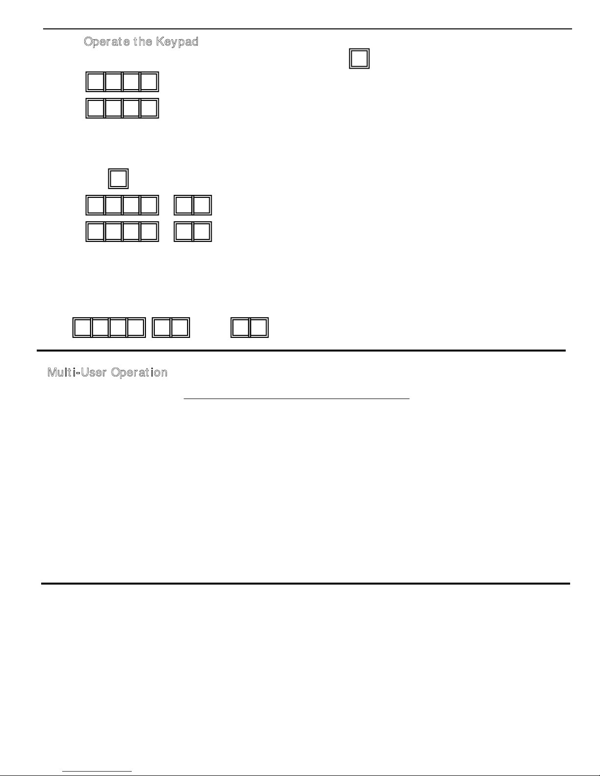
3) Operate the Keypad –Taking the data programmed above and other features in default value as reference
a) To command an output, enter it’s user code. Press is not required.
b) The Personal Master Code is a Super User Code to control the outputs. This feature allows
the owner to use only one code to operate several keypads if they have the same
Master Code but different User codes. Enter the personal Master Code and validate via
the key and corresponding output number.
3 2 8 9 ---
Lockout is reset and keypad resumes normal operation
* * * *
c) Enter false codes into the keypad to test the security. The keypad considers 4 digits as
1 code and it generates 5 beeps for each unsuccessful entry. The keypad will lock for 15
minutes after 10 unsuccessful code entries. Normal operation will resume after 15 minutes
have expired or it may be reset with the Master User Code at any time during lockout.
pause
C) Multi-User Operation – Operation Example
The following steps are an example only
1) Requirement
a) Multi-User Mode Operation
b) Change factory set Master Code “0000” to a Personal Master Code “3289”.
c) Set 1st User Code in Group 1 of 8321
d) Set 2nd User Code in Group 1 of 1122
e) Set 3rd User Code in Group 1 of 3333
f) Set 1st User Code in Group 2 of 6854
g) Set 2nd User Code in Group 2 of 5432
h) Set Output 1 to Momentary Mode, 1 second duration
i) Set Output 2 to Start / Stop Mode
j) Set the keypad to lock for 15 minutes after 10 successive false codes

10
0 0 0 0 ----- System is set to programming mode using factory set Master User Code
* *
10 3 2 8 ----
3289 has been stored as the new Personal Master Code & Super User Code
#9
1 8 3 20 0 1
002
003
--------8321 has been stored as 1st user code in Group 1
with duress code function
#10 2
1 1 1 2 ----------1122 has been stored as 2n
d
user code in Group
1 with duress code function
#20 2
1 3 3 2 ----------3322 has been stored as 3rd
user code in Group
1 with duress code function
#20 2
0 6 8 -----6854 has been stored as 1st user code in Group 2
#51 4
0
2
2 5 4 3 -------------5432 has been stored as 2n
d
user code in Group 2
#22
5 ----------------------------Output 1 is set to Momentary Mode with1 second duration
#1 1
#05 ---------------------------- Output 2is set toToggle Mode
1
6 ------------------------- Keypad is set to lock for 15 minutes after 10 successive false
codes
#0 1 0
** ------------------------------- Keypad exits programming mode. All changes are stored, system is
ready to use
#
#
8 3 2 1 # ----------------------------------- Output 1activates for 1 second
1 1 2 1 # ---------------------------------- Output 1activates for 1 second
3 3 2 2 # ---------------------------------- Output 1activates for 1 second
2) Programming
Note:
a) In case of incorrect entry during programming, cancel with the key, or, wait 10
seconds, then re-try.
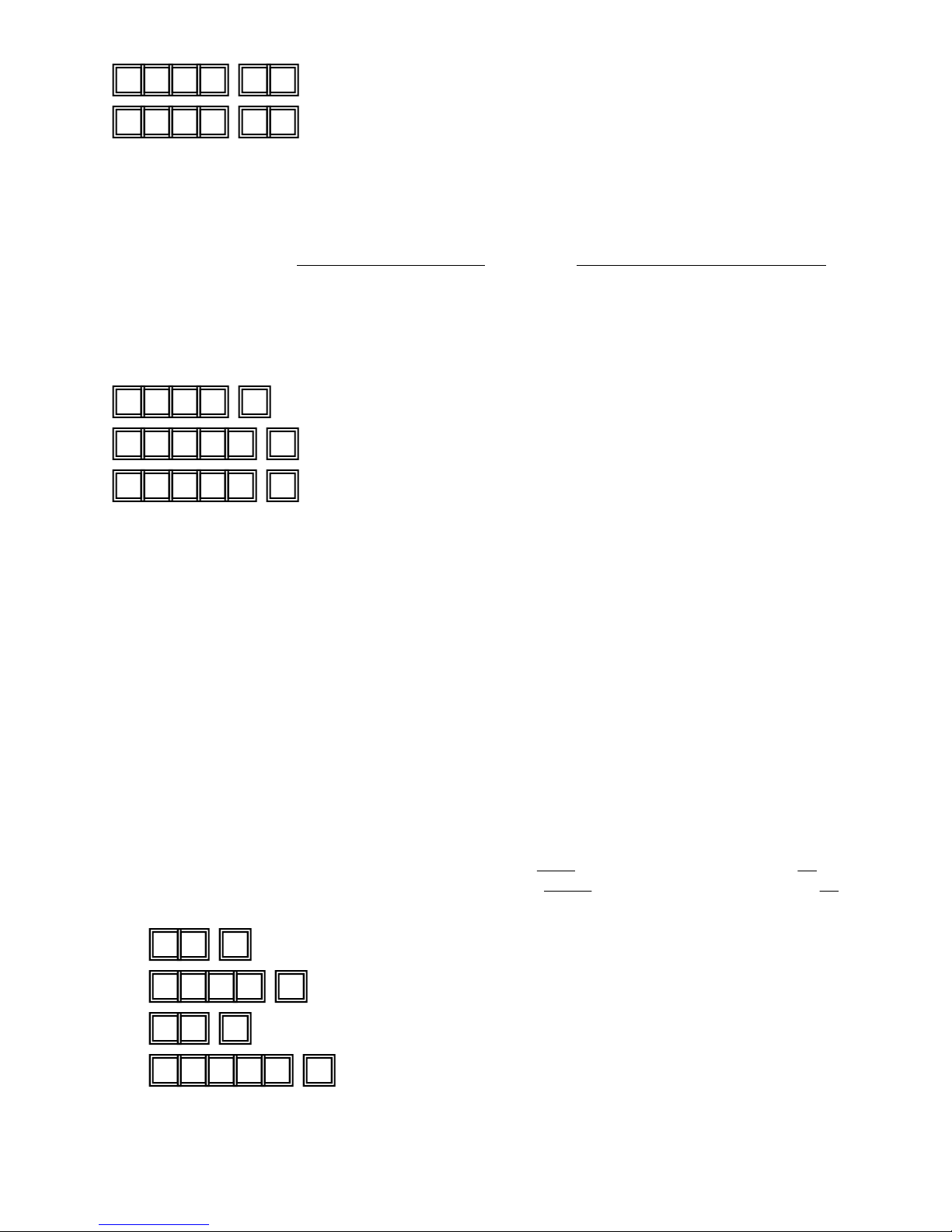
3) Operating the Keypad – Taking the data programmed above and other features in default value as
reference
a) To control Output 1 enter any one of the user codes in Group 1 and validate via the
key
#
6 8 5 4 # ----------------------------------- Output 2 Starts or Stops (toggle mode)
5 4 3 2 # ---------------------------------- Output 2 Starts or Stops (toggle mode)
b) To control Output 2 enter any one of the user codes in Group 2 and validate via the
key
#
c) Programming function 02 is a Super User Code to control the outputs. This feature
allows the owner to use only one code to operate several keypads if they have the
same Master Code but different User Codes. Enter the Personal Master Code and
validate via the key and the corresponding output number.
11
3 2 8 9 # ------------------------------- Output 1activates for 1 second
1
3 2 8 9 # ------------------------------- Output 2 Starts or Stops (toggle mode)
2
0 3 2 1 # ---
Duress output activates (switches to ground) & Output 1 activates for 1 second
3 1 2 2 # ---
Duress output activates 9switches to ground) & Output 1 activates for 1 second
3
5 3 2 2 # ---
Duress output activates 9switches to ground) & Output 1 activates for 1 second
1
Output 1 starts
d) The Duress codes do not need to be programmed. The keypad determines them
automatically by increasing the first digit in Group 1 by two units. All User Codes
have Duress Code function
Example: User Codes in Group 1 Corresponding Duress Codes
8321 0321
1122 31223
3322 53221
To activate the Duress function, enter the Duress Code(s)
Note:
The Duress Code has double actions. It activates the Duress Output and at the same
time activates Output 1 as if User Code 1 has been used. The Duress Code can always
activate or deactivate (in Start / Stop mode) Output 1, but cannot deactivate the Duress
Output. Only the User Code in Group 1 can reset (deactivate) the Duress Output.
e) The accelerated Code is the first two digits of the User Code. If Output 1 has been
programmed in Start / Stop mode with Accelerated Code )Programming Option 42,
for users in Group 1 & Programming Op tion 52 for user codes in Group2), it is
possible to activate Output 1 with only the first 2 digits of the User Code(s).
Deactivating the Output requires the full User Code(s) in their code group to be
entered.
Example: Output 1 has been re-programmed to Start / Stop mode with Accelerated Code
(Programming Option 42)
With the Complete Code of 1 st user in Group 1 of: 8321 The Accelerate Code will be 83 .
With the Complete Code of 2 nd user in Group 1 of: 11223The Accelerated Code will be 11.
8 3 #
8 3 2 1
--------------------
-------------
Output 1 Starts
Output 1 Stops
1 1 # -------------------- Output 1 Starts
1 1 2 2 --------- Output 1 Stops
3 #
#

12
3 2 8 9 ---------Lockout is reset and keypad resumes normal operation
#
*
3 2 8 9 ---------Keypad is now in Programming Mode
*
#
1 0 5 #
2 3 #
* *
f)
D) Delete User (Multi-User Mode)
If you need to delete a user who has left the company or who no longer has authority
To enter the protected area:
1) Enter System Programming mode with the Personal Master Code and the key
2) Enter the User Number (00-99 for Output 1; 0-9 for Output 2) and the key to
delete the user code
If you want to delete User Number 05 in Group 1, press:
If you want to delete User Number 03 in Group 2, press:
3) You may delete other user code(s) in this fashion
4) Exit the programming mode by pressing the key when finished
Enter false codes into the keypad to test the security. The keypad will lock for 15 min-
utes after 10 unsuccessful code entries. Normal operation will resume after 15 minutes
have expired or it may be reset with the Master User Code at any time during lockout.
Specifications
Specifications subject to change without notice.
* Operating voltage 12V – 24V AC/DC No jumper selection required for full voltage range
* Current 10mA@ 12 VDCstandby – 100mA peak (both relays activated)
* Environmental Temperature - 30oC to +70oC
* Ambient Humidity 5 – 95 % relative humidity non-condensing
* Environment All weather IP 66
* Operation Modes a) Single User Mode, Auto or Manual Code Entry
b) Multi-User - 100 user codes for output 1 (user number 00-99),
Auto or Manual Code Entry
-10 user codes for output 2 (user number 0-9), Auto or
Manual Code Entry
* User Code Combinations a) Single User Mode – 10,000 (non-volatile memory)
b) Multi-User Mode – 111,110,000 (non-volatile memory)
* Input Sensing Terminals a) Egress Input – Normally Open sinking to Ground (-) )-(dnuorgotgniknisnepOyllamroN–tupnInoitisoProoD)b )-(dnuorgotgniknisnepOyllamroN–lortnoCpotS1yaleR)c
* Relay Output Contacts Output 1 Dry contact 5A/30VDC max normally open, normally closed
amCDV03/A1tcatnocyrD2tuptuO x normally open, normally closed
* Tamper Switch Contact Dry contact 50 mA max normally closed
* Duress, Interlock & key active
Am001/CDV42evitcanehwdnuorgotsknisrotcellocnepONPNtuptuo
* Keypad timeout during code a) Each digit maximum entry time limit -- 10 seconds
umixamedochcaE)byrtne m entry time limit – 30 seconds
)mm651(ni41.6snoisnemid* H x 4.1 in (103mm) Wx 2.76 in (50mm) D
ten)smarg089(sdnuop61.2thgieW* )kcalB(leetSdetaoCredwoP&dezidonAgnisuoH* leetssselniatS)mm5.1(ni60.0etalPecaF*
* Key Buttons Cast Metal Back-lit Buttons
13
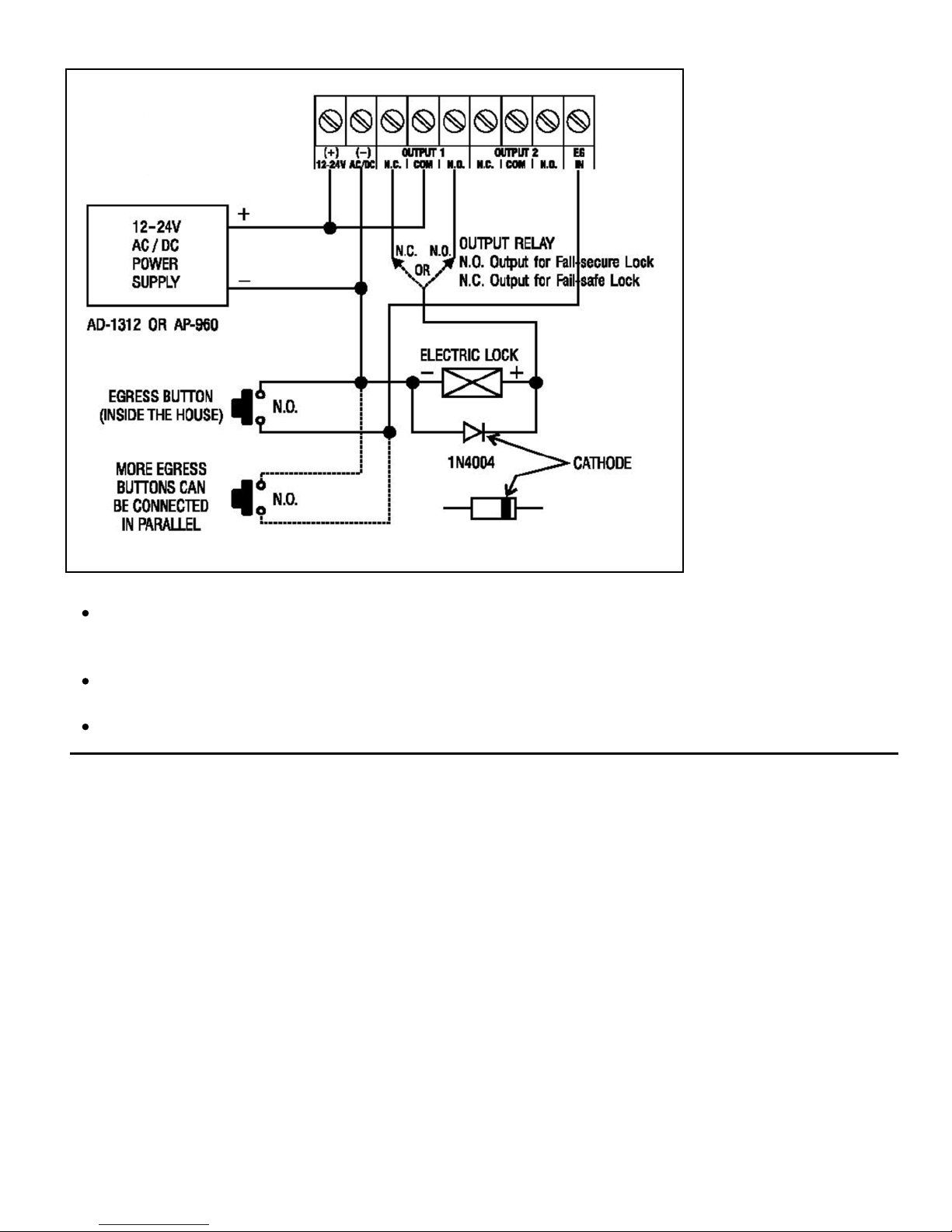
1) Basic wiring of Stand Alone Door Lock Installation
Note:
Connect the 1N4004 as close as possible to the lock in parallel with the lock terminals to
absorb the back EMF to prevent damage to the keypad. The 1N4004 is not required if the
electric lock is AC operated.
To avoid Electro-Static-Discharge from interfering with the operation of the keypad, always
ground the (-) terminal to earth ground.
Always connect Door Sensor terminal to (-) ground if not used.

14
2) Example of wiring with stand alone door lock with inhibit authorization code
Use output 2 as authorization control. The owner may key in the user code 2 to stop
operation of the electric lock at night or after office hours to prevent unauthorized access.
Set output 2 to Start / Stop (toggle) Mode (Program Option 51) for ON-Off control.
Simply connect the “output 1 inhibit” (O/P 1 I NHIB) terminal with output 2 as shown in the
wiring diagram. User code 1 is invalid while the “O/P 1 INHIB” terminal is shunted to ground
with user code 2.

15
3) Basic Wiring of an Inter-lock System using two keypads
An inter-lock system needs two door controllers. This application example uses two Post Mount Keypad
with simple cross wire connection on the “Output 1 Inhibit” and “Inter-lock Control Output” terminals. It
is necessary to link up the “(-) GND” terminals of the two keypads as common ground to achieve
the inter-lock logic function.
Use keypad to open door from outside
Press egress button to open door from inside
Connect the door magnetic sensors on the doors to monitor position
While door 1 is open, door 2 is forced to stay closed or vide versa
Use N.O. relay output for fail-secure lock; and N.C. output for fail-safe lock
Please consult “NOTE” stated in application example (1)

16
(B) DOOR SENS
a) Door Auto Relock – the system will
immediately re-lock the door after a valid
access has been gained to prevent “tailgate”
entry.
b) Door Forced-open alarm – The keypad will
generate an instant alarm if the door is
forced to open. Enable the function with
Program Option 801
c) Door Propped Open Alarm – The keypad
will generate an alarm if the door is left
open longer than the pre-set time. Enable
the function with Program Option 9 with
duration of 1 to 999 seconds.
With the help of a normally closed door d) Inter-lock Control– When the door is open
Position sensor (usually a magnetic door the inter-lock output of the keypad will give
switch)on the door to set up the following a (-) command to de-activate the other
functions. keypad in an inter-lock system.
Application Examples for Auxiliary Terminals

17

18
Open Collector
Output ---
Output switches to
ground when
activated
N.O. CONTACT
Output ---
Output switches to
ground when
activated
EQUIVALENT
APPENDIX
Dry Contact
A dry contact means that no electricity is connected to it. It is prepared for free connection.
The relay contacts provided by the Post Mount Keypad are dry contacts.
N.C.
Normally Closed, the contact is closed circuit in a normal status. It is open when activated.
N.O.
Normally Open, the contact is open circuit in a normal status. It is closed when activated.
Transistor Open Collector Output
An open collector output is equivalent to Normally Open (N.O.) contacts switching to ground
similar to a relay contact connecting to ground. The transistor is normally OFF, and it’s
output switches to ground (-) when activated. The open collector can only provide switching
function for low power requirements but is usually good enough for control of an alarm
system . The Duress, Inter-lock and Key Active outputs of the Post Mount Keypad are open
collector outputs.
Table of contents
Popular Keypad manuals by other brands


ADEMCO
ADEMCO Galant 6128 RFH installation guide

DMP Electronics
DMP Electronics ePAD 5.0 Programming guide

DSC
DSC PowerSeries LCD5511 Installation insrtuctions

Gianni Industries
Gianni Industries DG-800 instruction manual

DMP Electronics
DMP Electronics Thinline 7463 Installation and programming guide

Kramer
Kramer RC-206 quick start guide


