All-sun EM3610 User manual

Battery Internal Resistance Meter
3610
Users Manual
Read this manual thoroughly before use

1
INTRODUCTION
This Battery Internal Resistance Meter is an intelligent
instrument which can be used for battery online
measurements. It can be used to measure battery terminal
voltage and internal resistance as well as to make normal
resistance measurements. The internal resistance is
measured with the international standard AC signal
(1000Hz ± 10%) by means of four-wire method to eliminate
the impact of the resistance of the test leads on the
measured value, and the battery voltage can also be
measured by the same connection method.
It is applicable for measurements of internal resistance of
Lithium-ion, nickel-hydroxide, lithium-manganese cells or
assembled battery.
GENERAL SPECIFICATION
Overrange Indication: only figure " 1 " shown on the
display
Negative Polarity Indication: "
-
" shown on the display
automatically
Operating Environment: temperature: 0 ~ +40°C
relative humidity: < 80%
Temperature Coefficient:
0.1 x (specified accuracy)/°C (< 18°C or > 28°C)
2
6
1
2
3
4
5
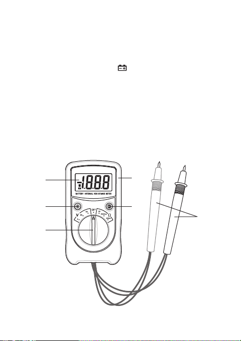
STRUCTURE
Storage Environment: temperature: -10 ~ +45°C
relative humidity: < 85%
Battery: 9V battery, 6F22 or equivalent, 1 piece
Low Battery Indication: " " shown on the display
Size: 150×83×44mm (only mainbody )
Weight: about 315g (including battery)

SPECIFICATIONS
Accuracy is specified for a period of one year after
calibration and at 18°C to 28°C, with relative humidity
< 75%. Accuracy specifications take the form of:
±([% of Reading] + [number of Least Significant Digits])
3
1. Display
3 1/2-digit LCD, with a max. reading of 1999
2. " " Button
Press this " " button to turn on the backlight. The
backlight will turns off automatically about 10 secs later.
3. Function / Range Switch
Used to select desired function and range as well as to
turn on or off the meter.
To preserve battery life, set this switch to the " OFF "
position when the meter is not in use.
4. " " Button
Press this " " button to hold the present reading on
the display, the symbol " " will appear on the display
as an indication. To exit the Data Hold mode, just press
this button again. " " disappears.
5. Holster
6. Test Probes

Battery Voltage
Range Resolution Accuracy
0 ~ 1.999V
2.00V ~ 19.99V
20.0V ~ 50.0V
1mV
10mV
100mV
± (1% + 2)
Range Resolution Accuracy
0 ~ 199.9m
200m ~ 1999m
2.00 ~ 19.99
0.1m
1m
10m
± (3% + 5)
Resistance/Battery Internal Resistance
4
5
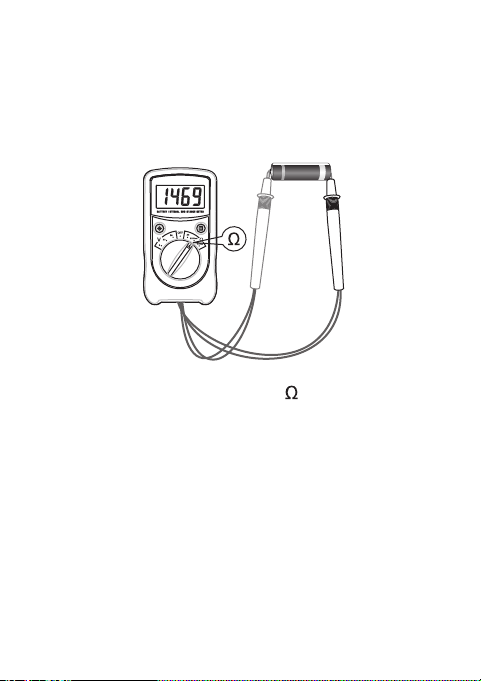
1. Set the range switch to desired range position.
2. Connect the red test probe to the positive terminal of
the battery to be measured and the black test probe to
the negative terminal of the battery.
3. Read the reading on the display.
4. If the display shows " 1 ", it means that the measured
value exceeds the selected range and you should set
the range switch to a higher range position.
Note:
1. When the test probes are in open circuit state, the
display will show " 1 " as an overrange indication.
OPERATION INSTRUCTION
Measuring Battery Internal Resistance
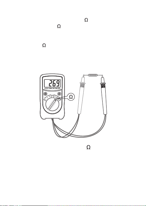
1. Set the range switch to desired range position.
2. Connect the test probes across the resistor to be
measured.
3. Read the reading on the display.
Note:
1. The resistance is measured by the meter with an AC
signal so that the capacitance value and inductance
Measuring Resistance
6
2. For measurements in the 200m range, set the range
switch in the 200m range position and short the two
test probes, the display will show a reading. This
reading must be subtracted from all the measurements
in the 200m range.

7
Measuring Battery Voltage
value of the resistor under test can affect the
measurement result.
2. The frequency of the meter's test signal is 1kHz.
3. When the test probes are in open circuit state, the
display will show " 1 " as an overrange indication.
4. Before measurement, disconnect all power to the circuit
to be tested and discharge all capacitors thoroughly.
5. For measurements in the 200m range, set the range
switch in the 200m range position and short the two
test probes, the display will show a reading. This
reading must be subtracted from all the measurements
in the 200m range.

8
1. Set the range switch to desire Vrange position.
Note: a. The range you select must be higher than the
battery's rated voltage.
b. If the magnitude of the battery's voltage is not
known beforehand, set the range switch to the
highest range position and then reduce it
range by range until satisfactory resolution is
obtained.
2. Connect the red test probe to the positive terminal of
the battery to be measured and the black test probe to
the negative terminal of the battery.
3. Read the reading on the display. The polarity of red test
probe connection will be indicated as well.
NOTE
1. Do not apply a voltage higher than 50V between the
test probes; otherwise the meter will be damaged.
2. When you measure battery, the red test probe must be
connected to the battery's positive terminal and the
black test probe must be connected to the battery's
negative terminal.
3. When you measure battery internal resistance, you
must connect the test probes to the battery directly. To
ensure measurement accuracy, do not use other lead(s)
for connection; otherwise the resistance of the lead(s)

9
will be included in the measurement result.
4. Remove the battery in the meter's battery compartment
from the meter if you don't use the meter in a long
period.
5. Do not use the meter where explosive gas, vapor, or
dust is present.
6. To void electric shock and personal injury, do not touch
any naked conductor with hand or skin and do not
ground yourself.
7. Do not use the meter if it is damaged or if it operates
abnormally.
8. To avoid damage to the meter, do not apply any AC
signal between the test probes.
BATTERY REPLACEMENT
When the symbol " " appears on the display, the battery
is low and should be replaced immediately.
To replace battery, remove the screws on the battery cover
and remove the battery cover. Replace the exhausted
battery with a new one of the same type (9V, 6F22 or
equivalent). Reinstall the battery cover and the screws.

10 V110507
DISPOSAL OF THIS ARTICLE
Dear Customer,
If you at some point intend to dispose of this article,
then please keep in mind that many of its components
consist of valuable materials, which can be recycled.
Please do not discharge it in the garbage bin, but
check with your local council for recycling facilities in
your area.
DECLARATION
1. This manual is subject to change without notice.
2. Our company will not take the other responsibilities for
any loss.
3. The contents of this manual can not be used as the
reason to use the meter for any special application.
Table of contents
Popular Measuring Instrument manuals by other brands


Level Pro
Level Pro ULTRAPRO 1000 instruction manual

dallmeier
dallmeier SMatrix DMX2400 Service

Hanna Instruments
Hanna Instruments HI 93705 instruction manual

Dostmann Electronic
Dostmann Electronic P4000 Series Operating instruction

Hach
Hach QbD1200 AutoSampler user manual

Gespasa
Gespasa MGE-110 instruction manual

Siemens
Siemens SENTRON 7KT PAC1200 System manual

SICK
SICK FlexChain operating instructions

PRECISION DIGITAL
PRECISION DIGITAL NOVA PD560 Series instruction manual

IFM
IFM DI5029 installation instructions

NK
NK EmPower Oarlock quick start guide

IFM Electronic
IFM Electronic efector 300 SI0519 operating instructions