Allanson ACL-SC3C4A-DMX User manual
2
4.3 DMX Dimming Instruction:
CH1 0-255
CH2 0-255
CH3 0-255
Each DMX decoder occupied 3 DMX
addresses when connecting the DMX console. PWM 0-100% (LED R)
PWM LED G)0-100% (
PWM LED B)0-100% (
CH1
CH2
CH3
DMX Consol e DMX Decoder
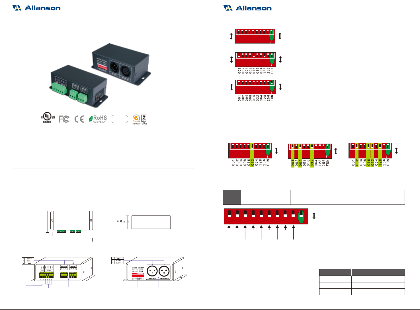
Dip Switch Operation:
4.
RDM Mode: The dip switch 1-10 are OFF.
FUN=ON (the 10th dip swit ch=ON)
Self-testing Mode:
FUN=OFF (the 10th dip swit ch=OFF)
DMX Mode:
Setting DMX addr es ses with dip swit ch 1-9
FUN =OFF (
the 10th dip swit ch
)Mode
=OFF
DMX
4.1 How to set DMX addr ess via dip switch:
E.g.1: Set Initial Addres s To 32. E.g.2: Set Initial Addres s To 37. E.g.3: Set Initial Address To 178.
001+004+032=37 002+016+032+128=178
4
4
4
1
1
1
111
2
2
2
222
3
3
3
333
4
4
4
444
5
5
5
555
6
6
6
666
7
7
7
777
8
8
8
888
9
9
9
999
ON
ON
ON
DIP
DIP
DIP
0
1
0
1
0
1
OFF
ON
OFF
ON
OFF
ON
OFF
ON
OFF
ON
OFF
ON
10
10
10
10 10 10
ONDIP ON ON
DIP DIP
4.2 Self-testing Mode:
DMX address value=the total value of (1-9), to get the plac e value when in “ON” position,
otherwise will be 0.
e.g., the default ed initial address is 1, please nd
their corr esponding relationships in the form.
FUN =ON (
the
10th dip swit ch = ON) Self-tes ting Mode
1=on 4=on 7=on 8=on 9=on2=on 5=on
3=on 6=on
Self- test
Function
1-9=o
Dip Switch
Static
Black
Static
Red
Static
Red
Static
Green
Static
Green
Static
Blue
Static
Blue
Static
Yell ow
Static
Yell ow
Static
Purpl e
Static
Purpl e
Static
Cyan
Static
Cyan
Static
White
Static
White
7 Colors
J umping
7 Colors
Jumping
7 Colors
Smooth
7 Colors
Smooth
[Attn] When se ver al dip switches ar e on, subjected to the highes t switch value .
As the gure above shows, the eect will be 7 colors smooth at 7 speed level.
For changing eects (Dip Switch 8 9=on):/
DIP swit ch 1-7 is used to realize 7 speed
levels. (7=on, the fas tes t level)
OFF
ON
12345678910
warranty
5 years
ACL-SC3C4A-DMX
DMX/RDM 3CH CV DECODER (Sub-Controller)
ACL-SC3C4A-DMX ACL-SC3C4A-DMX
64mm
125mm
115mm
Dimming Range:
Working Temper ature:
Package Size:
Weight (G.W.):
0~100%
-30°C ~65°C
L135×W70×H50(mm)
305g
1. Pr oduct Par ameter:
Input Signal:
Input Voltage:
Curr ent Load:
Output P ower:
DMX512 Sock et:
DMX512, RDM
12~24Vdc
4A×3CH 12A
144W/432W/576W(12V/36V/48V)
XLR-3, Green Terminal
Max.
Max.
2. Product Size:
3. Conguration Diagram:
1
12345678910
ONDIP
Power Input
Sock et
12
3
Green
Terminal
(with amplier
function)
XLR-3
Addres s
Dip Switch
1 2
3
LED Lamps
Connection
Sock et
www.allansonled.com
ACL-SC3C4A-DMX
W
communication,
achieves
remote management of reading and writing DMX address (DMX mas ter controller
must recognize the RDM protocol). Equipped with DMX standard XLR-3, green terminal interf ace. Realize
0-100% dimming or dierent lighting eect; workabl e with singl e color, bi-color or RGB LED lamps.
ith the standard RDM remote device management protocol, it supports DMX512 signal bi-dir ectional
4
6. Attention:
7. Warranty Agr eement:
6.1 The product shall be ins tall ed and serviced by the qualied person.
6.2 This product is non-wat erpr oof. Pl ease avoid the sun and rain. When ins tall ed outdoors please ensur e
it is mounted in a water proof enclosur e.
6.3 Good heat dissipation will prolong the working life of the controller. Please ensure good ventilation.
6.4 Pl ease check if the output voltage of the LED power supply used comply with the working voltage of
the product.
6.5 Please ensure that adequate sized cable is used from the controller to the LED lights to carry the current.
Pleas e also ensure that the cable is s ecured tightly in the connector.
6.6 Ensur e all wire connections and polarities ar e corr ect before applying power to avoid any damages to
the LED lights.
6.7 If a fault occur s, please return the product to your supplier . Do not attempt to x this product by yourself .
7.1 We provide lifelong technical assistance with this product:
A 5- year warranty is given from the date of purchase. The warranty is for free repair or replacement
if cover manufacturing faults only.
For faults beyond the 5-y ear warranty, we reserve the right to charge for time and parts.
7.2 Warranty exclusions below:
Any man-made damages caused fr om improper operation, or connecting to exces s voltage and
overloading.
The product appears to have exces sive physic al damage.
Damage due to natural disaster s and force majeure.
Warranty label, fr agile label and unique barcode label have been damaged.
The product has been replac ed by a brand new product.
7.3
7.4 Any amendment or adjus tment to this warr anty mus t be approved in writing by our company only.
★This manual only applies to this model. reserv e the right to mak e changes without
We prior notice.
Repair or replac ement as provided under this warr anty is the exclusiv e remedy to the cus tomer.
We shall not be liabl e for any incident al or consequential damages for breach of any stipulation
in this warr anty.
5.2 The connection diagr am of two DMX terminals:
05.16.2019
3
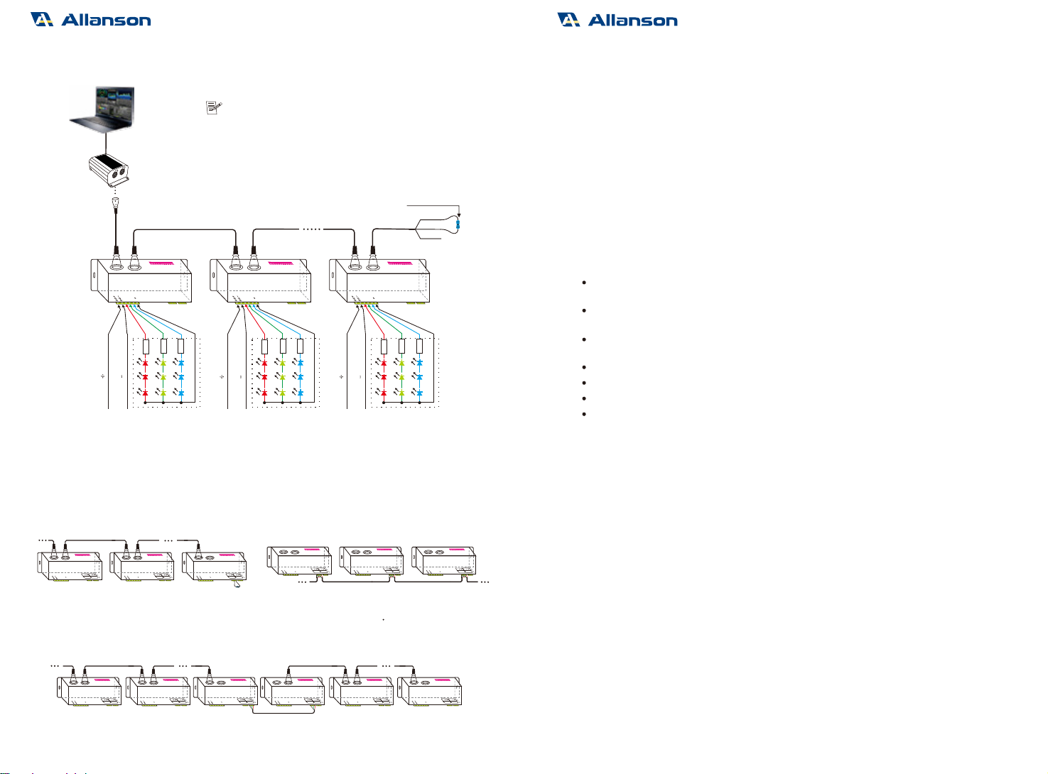
5. Wiring Diagr am:
DMX/RDM Signal
DMX/RDM signal
DMX Console
Equipped with 2 types DMX terminals for users ’ sel ection. The
diagram tak es XLR-3 terminal as a exampl e, same connecting method for the
green terminal (with amplier function) .
Terminal resis tor
5.1 Decoder can be connected to a variety of standar d DMX512 devices:
*An amplier is needed when mor e than 32 decoders are connected, signal amplic ation should not be more than
5 times continuously.
*
terminal resistor at the end of each line.
If the recoil e ect occurs because of longer signal line or bad line quality, pl ease try to connect 0.25W 90-120Ω
5 dc-24V
5 dc-24V5 dc-24V
Input Power
Input PowerInput Power
5.3 The connection diagr am of :AMP signal amplier terminal
XLR-3 Connected in P ar all el Green Terminal Connected in P ar all el
D M X s ignal input
*when too many DMX decoders are c onnected or signal line is too long, signal
amplication should be no more than 5 times continuousl y.
AMP interf ace c an be used f or signal amplic ation
These 2 terminals can be connected in a mixed way
DMX/RDM Signal
DC
+
DC
+
DC
+
DC
-
DC
-
DC
-
R
R
RG
G
GB
B
B
R
3
R
3
R
3R
2
R
2
R
2R
1
R
1
R
1
CH1
CH2
Ch3
V
123 4 5 67 8 9 10
ON
CH1
CH2
Ch3
V
1234 5 678910
ON
CH1
CH2
Ch3
V
1234567 8 910
ON
GND
DATA+
DATA-
DMX IN
G
DMX AMP
G
CH1
CH2
Ch3
V
123 456 7 8910
ON
DMX IN
G
DMX AMP
G
CH1
CH2
Ch3
V
12 3456 7 8910
ON
DMX IN
G
DMX AMP
G
CH1
CH2
Ch3
V
12 3456 7 8 910
ON
DMX IN
G
DMX AMP
G
CH1
CH2
Ch3
V
12345678910
ON
DMX IN
G
DMX AMP
G
CH1
CH2
Ch3
V
12345678910
ON
DMX IN
G
DMX AMP
G
CH1
CH2
Ch3
V
12345678910
ON
AMP
DMX IN
G
DMX AMP
G
CH1
CH2
Ch3
V
12345678910
ON
DMX IN
G
DMX AMP
G
CH1
CH2
Ch3
V
12345678910
ON
DMX IN
G
DMX AMP
G
CH1
CH2
Ch3
V
12345678 910
ON
DMX IN
G
DMX AMP
G
CH1
CH2
Ch3
V
1234567 8 910
ON
DMX IN
G
DMX AMP
G
CH1
CH2
Ch3
V
1234567 8 910
ON
DMX IN
G
DMX AMP
G
CH1
CH2
Ch3
V
12345678910
ON
ACL-SC3C4A-DMX ACL-SC3C4A-DMX ACL-SC3C4A-DMX
ACL-SC3C4A-DMX
www.allansonled.com
Other Allanson Media Converter manuals

Popular Media Converter manuals by other brands


Baumer
Baumer HUBNER BERLIN MHGE 100-HDmag Mounting and operating instructions

Cirrus Logic
Cirrus Logic CS4953xx Hardware user manual

Viessmann
Viessmann 5213 Digital 2 operating instructions

Samlexpower
Samlexpower SDC-5 owner's manual

Comtech EF Data
Comtech EF Data MBT-5000 User's installation and operation manual

Sony
Sony NXL-IP4F Operation manual