manuals.online logo
Brands
  1. Home
  2. •
  3. Brands
  4. •
  5. ALLEN & HEATH
  6. •
  7. Controllers
  8. •
  9. ALLEN & HEATH PL-1 User manual

ALLEN & HEATH PL-1 User manual

PL-1 User Guide AP5079 1
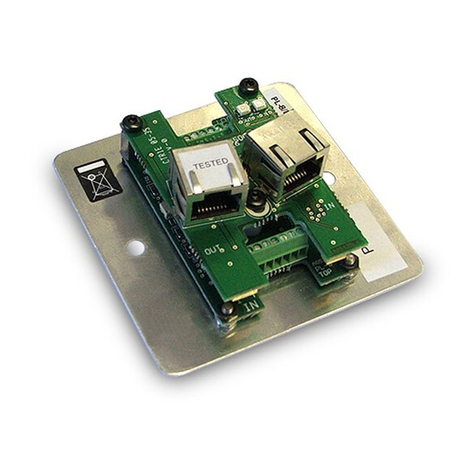
Introduction The PL-1 is a remote control device available for use with
the Allen & Heath DR66 and DR128 audio mix processors. It is a wall plate or
furniture mounted module comprising plastic control panel and attached circuit
assembly. It can be mounted in a single unit wall box using a standard face
plate (UK, EU or US version supplied). A pre-cut brushed aluminium EU
(AA5029) or US (AA5030) plate is supplied. The PL-1 interfaces with the
DR66/128 rear panel REMOTE port. The number of PL-1 units which may be
connected is determined by the number of remote switch and tally output lines
from the DR system and how many you wire to each PL unit. The wall plate
switch and indicator functions are programmed using the Allen & Heath WinDR
software. Space is provided on the control panel for custom labelling of the
programmed functions. The following combination of controls makes the PL-1
ideal as a wall mounted room remote controller in installed audio systems. The
installer can program the unit so that the non-technical operator has local
control of volume, mute, source select, and patch changes which reconfigure
the room for different functions.
4 switches can be assigned for level up or down control (input, output, or
crosspoint), mute toggle or patch recall.
4 LED indicators (DR66 only) can be assigned to display input or output
channel mute status, or as patch related static indicators. Each can be wired to
display either red or green. Two DR66 outputs can be used to switch an LED
to red, green or yellow.
Custom labels Recessed areas are provided for fitting custom adhesive
labels. Recommended maximum sizes are 6x26mm and 26x9mm (height x
width).
Note : The PL-1 differs from the PL-2 only in that it
does not include the DR/iDR-switch LED adapter card.
This is not required as the LED series resistors are built
into the DR66 for which it is intended. To avoid
damage only use the PL-1 with the DR66 or DR128.
This product complies with the European
Electromagnetic Compatibility directives 89/336/EEC &
92/31/EEC.
NOTE: Any changes or modifications to the
equipment not approved by Allen & Heath could void
the compliance of the equipment. Whilst we believe
the information in this guide to be reliable we do not
assume responsibility for inaccuracies. We also reserve
the right to make changes in the interest of further
product development.
PL-1 User Guide AP5079 Issue 1
Copyright© 2003 Allen & Heath Ltd. All rights reserved.
IMPORTANT :
Observe the local standards which may apply
to the installation regarding the grade of cable and
installation methods.
To ensure operator safety ensure that any
exposed metal face plates are correctly bonded to
ground. Do not install the equipment where it is
subject to moisture, heat or vibration.
Connect this equipment to the Allen & Heath
DR66 or DR128 only. Test for correct wiring and
installation before switching the equipment on.
The DR66/128 provides opto-isolated contact
closure switch inputs and logic outputs with internal
series resistors. How these are wired to external
equipment is the responsibility of the installer.
Details are provided here for wiring to the PL-1 wall
plate. Allen & Heath do not assume responsibility
for any damage done to the equipment due to
incorrect or faulty installation.
PL-1 Wall Plate for DR66/128 AP5079
USERGUIDE
DR66 12 switches, 4 LEDs
DR128 8 switches, no LEDs
BATTERY / REMOTE connector REMOTE SWITCHES connector
2 PL-1 User Guide AP5079
Aligning the arrow keys The four switch
caps can be rotated so that the arrow faces up, down,
left or right. Decide which way you want them to face
according to function, for example volume or source
select.
To change them, first remove the four screws (B) and
lift away the PCB. Rotate the switch caps into the
required position. Reassemble the module.
A
A
B
B
BB
Mounting into the face plate A pre-cut
brushed aluminium UK (part number AA5029), EU
(AA5250) or US (AA5030) plate is supplied. A backing
box for the UK plate can be supplied (AA5220).
The assembled module fits into an ‘H’ shaped cutout in
the centre of the mounting plate. The module is held
using the two screws with plastic clamps provided (A).
Unscrew these from the module first. Dimensions are
in millimetres below.
Grounding a metal plate If the face
plate is metal make sure that it is correctly grounded to
ensure operator safety. The plate should be connected
to a local safety ground, not to the DR unit 0V common
or cable shield. Use a ground wire or physical contact
with a grounded back box.
Wiring standards Use flame retardent shielded
cable that meets the requirements of the installation.
We recommend the multi-stranded rather than solid
conductor type. Screw terminal blocks are provided for
the switch and LED connections. Use a small flat
bladed screwdriver. Ensure the wires are correctly
stripped and formed to allow sufficient service loop in
the backing box.
Wiring to the DR66/128 The following
shows the DR66 and DR128 connector pinouts.
Connect each SWITCH pin to the required PL-1 SW
terminal, and OUTPUT to the required R or G terminal.
Connect 0V COMMON to the 0V terminal. Connect the
cable shield to the DR unit D-connector shell.
LED1 R,G
LED2 R,G
LED3 R,G
LED4 R,G
SW1
SW2
SW3
SW4
Deciding the LED colour Wire the DR66
output to the G terminal for green, or to the R terminal
for red. Do not wire one output to both G and R. Wire
two DR66 outputs to G and R of the same LED to
switch it red, green or yellow (both G and R on).
Assigning the controls The function of the
LEDs and switches is assigned using the Allen & Heath
WinDR system manager software. First ensure the wall
plates are correctly wired to the DR unit. Plug your PC
into the DR RS232 port and run WinDR. For full details
refer to the WinDR application Help file.
Specification
390 ohms 100 ohms
100 ohms
390 ohms
CN1
SW3
SW4
RG RG
LED4 LED3
CN2
SW1
SW2
RG RG
LED2 LED1
Switch Press-to-make Current = 4mA max
LED 2-colour green / red Current = 6mA max
Max ground current = 40mA (4 switch, 4 LED)
Cable Shielded multi-core, 1k ohm max resistance
12
16
32
16
34
20
20
DIA 6
c
TOP
16
16
SW 2
0V COMMON
SW 1
LED 1G
LED 1R
LED 2G
LED 2R
SW 4
0V COMMON
SW 3
LED 4R
LED 4G
LED 3R
LED 3G
CN1 CN2
LEDs SW
SHELL

Other ALLEN & HEATH Controllers manuals

ALLEN & HEATH iDR-4 Operating and installation instructions

ALLEN & HEATH

ALLEN & HEATH iDR-4 Operating and installation instructions

ALLEN & HEATH PL Series User manual

ALLEN & HEATH

ALLEN & HEATH PL Series User manual

ALLEN & HEATH Xone 1D User manual

ALLEN & HEATH

ALLEN & HEATH Xone 1D User manual

Popular Controllers manuals by other brands

DCS 090 Series Reference manual

DCS

DCS 090 Series Reference manual

Danfoss Saginomiya RGE-Z3R2-7 instructions

Danfoss

Danfoss Saginomiya RGE-Z3R2-7 instructions

Mitsubishi Electric MELSEC iQ-R RD78G4 user manual

Mitsubishi Electric

Mitsubishi Electric MELSEC iQ-R RD78G4 user manual

ST Sitronix ST7038 manual

ST

ST Sitronix ST7038 manual

Furious FPV Fortini F4 OSD REV.3 user manual

Furious FPV

Furious FPV Fortini F4 OSD REV.3 user manual

Honeywell WEB-600E manual

Honeywell

Honeywell WEB-600E manual

HDL SB-DN-512DMX user manual

HDL

HDL SB-DN-512DMX user manual

Velleman CHLSC2 user manual

Velleman

Velleman CHLSC2 user manual

Valco Cincinnati VC3500 user manual

Valco Cincinnati

Valco Cincinnati VC3500 user manual

Shinko ACS-13A-*A Series instruction manual

Shinko

Shinko ACS-13A-*A Series instruction manual

Bernard LE Series Installation, start-up and maintenance instructions

Bernard

Bernard LE Series Installation, start-up and maintenance instructions

Honeywell HCE 60 Installation and operation

Honeywell

Honeywell HCE 60 Installation and operation

Mocbos DC 3600 XRi manual

Mocbos

Mocbos DC 3600 XRi manual

Hyperkin CADETP REMIUM instruction manual

Hyperkin

Hyperkin CADETP REMIUM instruction manual

NTN K-EGA57 instruction manual

NTN

NTN K-EGA57 instruction manual

Belimo AF120 US manual

Belimo

Belimo AF120 US manual

DEVI DEVIreg 850 Installation and user manual

DEVI

DEVI DEVIreg 850 Installation and user manual

Festo CDSA-D1-VX quick start guide

Festo

Festo CDSA-D1-VX quick start guide

manuals.online logo
manuals.online logoBrands
  • About & Mission
  • Contact us
  • Privacy Policy
  • Terms and Conditions

Copyright 2025 Manuals.Online. All Rights Reserved.