Alliance Rubber Oyster Banding Machine User manual
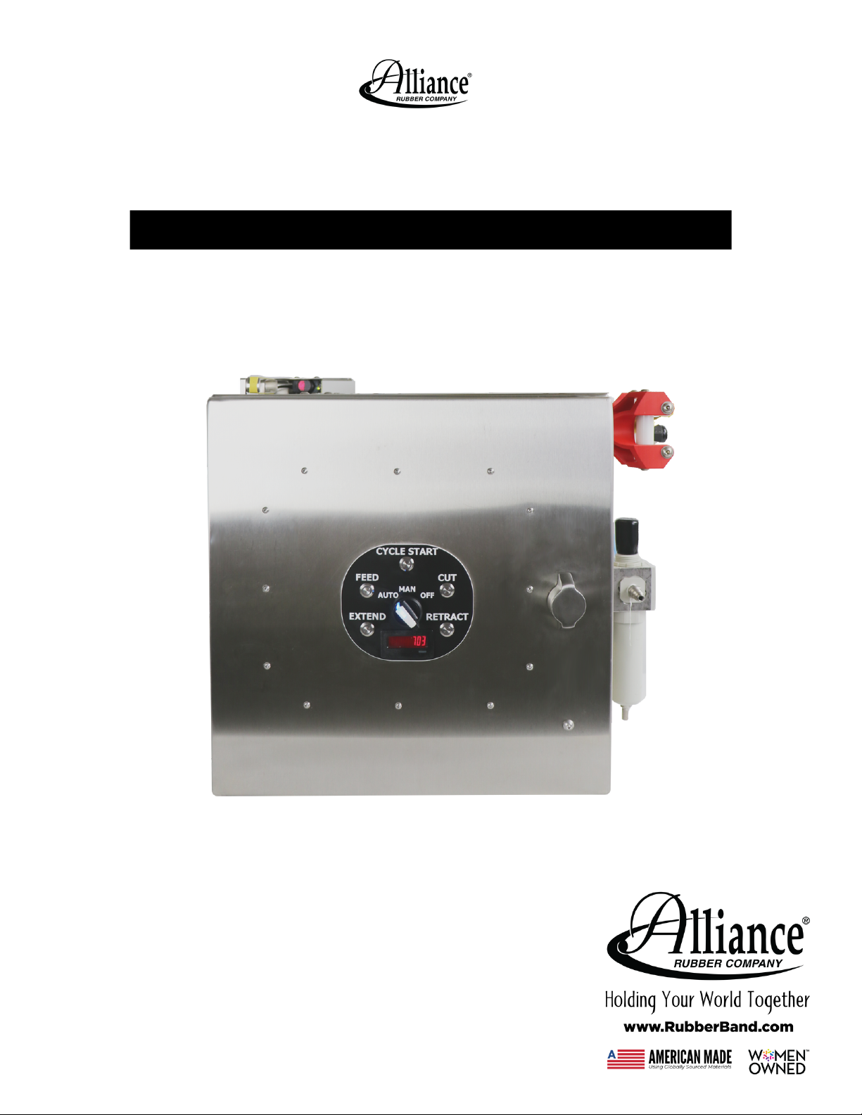
OYSTER BANDING
MACHINE
Operator's Manual
Manufactured in the USA by:
ALLIANCE RUBBER COMPANY
Hot Springs, AR
(2020.09)


User Diagram
Technical Diagram
Table of Contents
01
02
Diagram Page
Safety Procedures
Power and Air
03
03
Safety Page
Machine Setup
Functions: Manual Mode ("MAN")
Loading Bands
Functions: Auto Mode ("AUTO")
Unloading Bands
General Maintenance of Machine
Technical Instructions and Troubleshooting
04
06
07
11
13
14
15
Instructions Page
Enclosure
Enclosure
Core Assembly
Core Assembly
Core Assembly
Core Assembly
Core Assembly
17
19
21
23
25
27
29
Diagram Page
- Exterior
- Interior
- Mounting
- Knife and Stretcher Mounting
- Stretcher Assembly
- Knife Mechanism
- Feed Mechanism
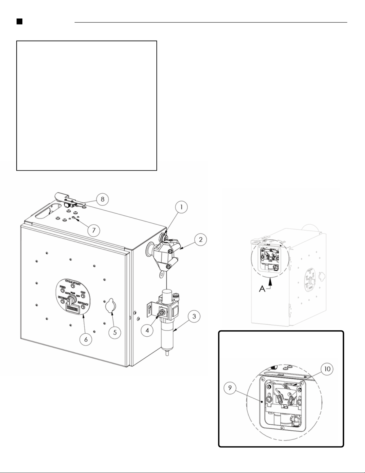
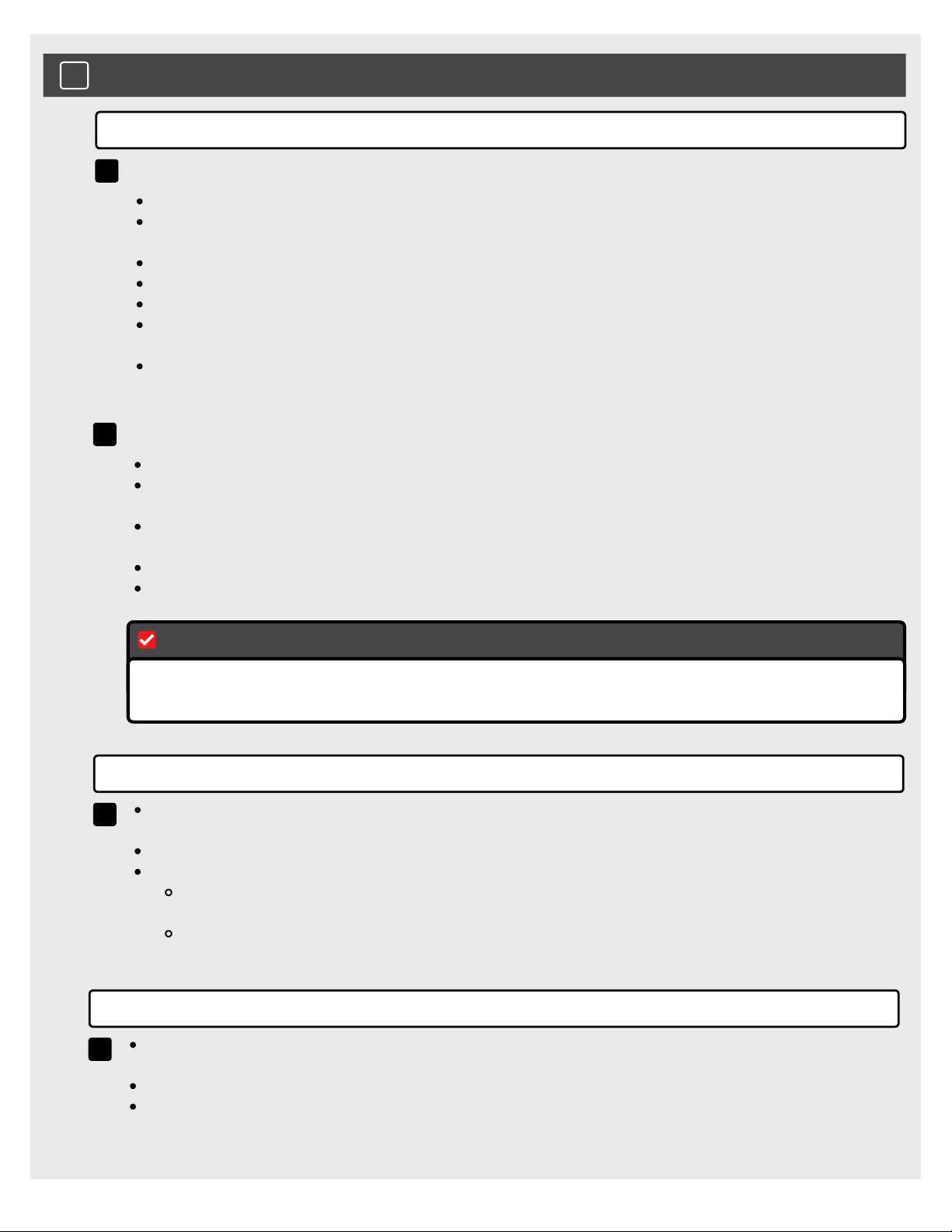
Power Connector
Feed Tube
Regulator
Compressed Air Inlet Valve
Door Lock
Control Panel
Feed Tensioner
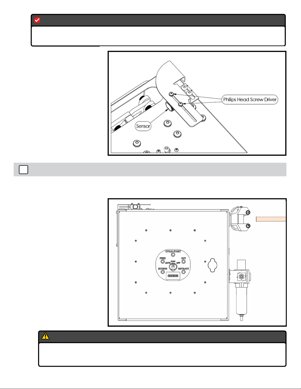
Sensor
Safety Shield
Fingers
1.
2.
3.
4.
5.
6.
7.
8.
9.
10.
User Diagram
DETAIL A
Fingers Assembly
Page 1 Oyster Banding Machine

Core Assembly
Main Enclosure
Subpanel Assembly
Lubricator
Control Box
Knife Blade
Fingers Cylinder
Feed Cylinder
Knife cylinder
1.
2.
3.
4.
5.
6.
7.
8.
9.
Technical Diagram
2020.09 Page 2
1Safety Procedures
FAILURE TO REMOVE APPENDAGES OR OTHER FOREIGN MATERIALS
FROM THE PATH OF THE KNIFE BLADE CAN RESULT IN PROJECTILES
OR LOSS OF APPENDAGES.
This device can be operated from 110-120 VAC~ 1.4A 50-60Hz and should be used with
the provided power cable. The connection can be directly attached using the 3-prong
plug attached to the provided power cable.
Caution
DO NOT LET ANY BODY PART CROSS THROUGH THE PATH OF THE
KNIFE BLADE AT ANY TIME.
DO NOT LET ANY BODY PART GET STUCK BELOW THE FINGERS
MECHANISM WHILE OPERATING.
Power Source
Alternatively, the power can be directly wired to a 12-24VDC auxiliary power supply
(battery) and should be used with the provided power cable. The connection can be
directly wired using the 2-pin plug attached to the provided power cable. The positive
terminal should be connected to the yellow wire.
This device requires a minimum of 100psi of clean and dry air for the inlet valve for proper
operation.
Air Source
Page 3 Oyster Banding Machine
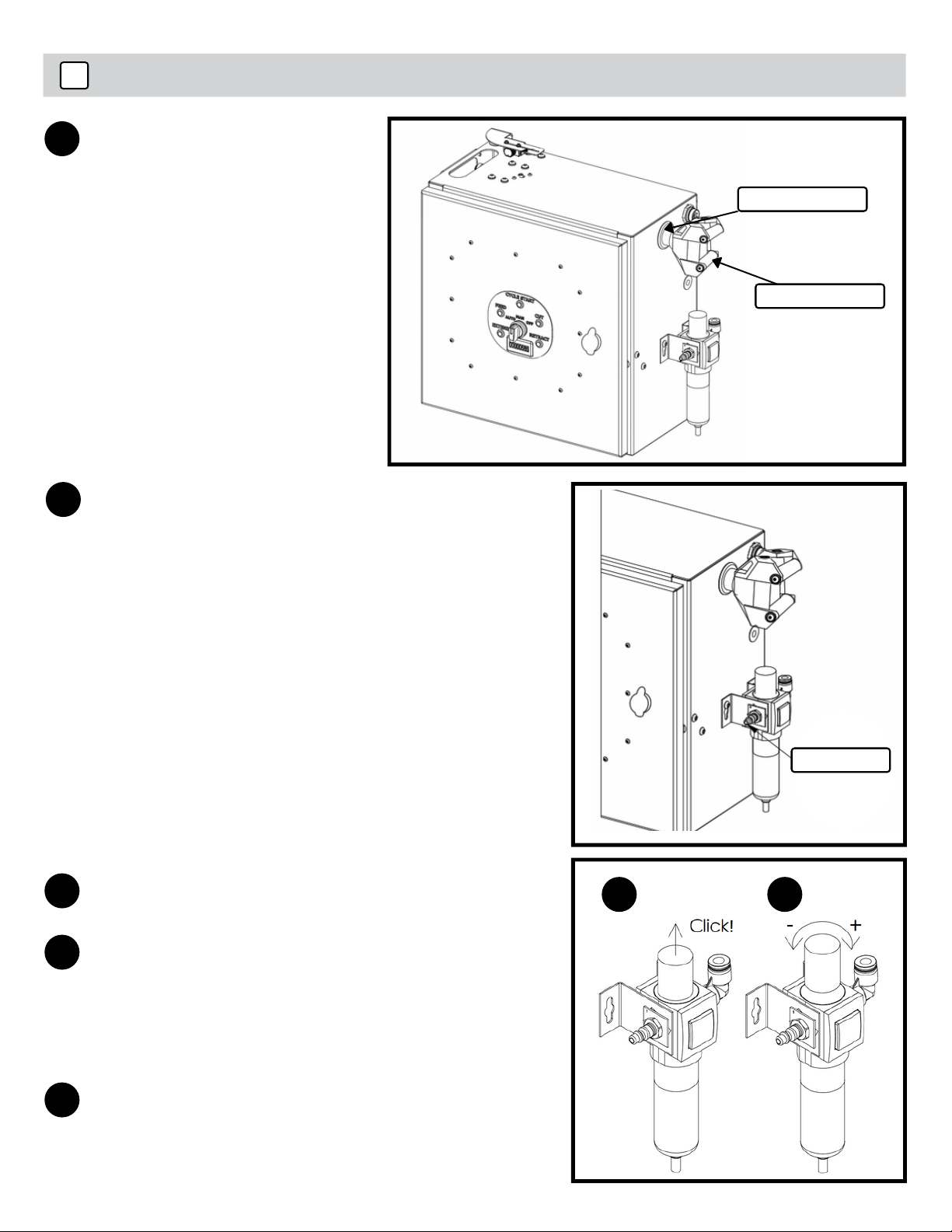
2Machine Setup
Attach the provided funnel
by placing it on the end of
the feed tube.
1
Connect an air compressor to the
regulator using the 1/4" male quick
connect coupling. Make sure the inlet
compressed air is regulated to 75 psi.
2
Pull up on the regulator adjustment knob
until it clicks to adjust pressure.
3a
Adjust the regulator pressure to 75 psi.
Turn the handle clockwise to increase the
pressure and counterclockwise to
decrease the pressure supplied to the
system. (It is not recommended for
pressure to be greater than 75 psi)
3b
Once the pressure is adjusted to 75 psi,
push back down on the handle until you
hear a click to lock the handle in place.
3c
3a 3b
Feed Tube
Funnel
Coupling
2020.09 Page 4

Connect power cable to the
labeled power connector
and the other end either to a
3-prong outlet (120VAC).
Please see page 3
4
Male End View
AC (in)
1 = WHITE
2 = RED
3 = GREEN/YELLOW
4 = ORANGE
5 = BLACK
Female End View
(on machine)
Close the door and lock it.
5
If the door is open, the safety switch will not allow the machine to function.
IMPORTANT!
Power
Connector
Door Lock
Page 5 Oyster Banding Machine

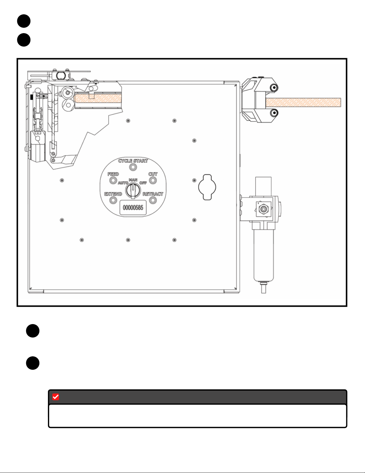
3Functions: Manual Mode ("MAN")
Flip the switch on the control board to "MAN" and confirm that each of the following
buttons work properly. In manual mode, each function can be independently
operated to assist in band loading or troubleshooting.
1
KEEP ALL GUARDS AND COVERS IN PLACE AT ALL TIMES
IMPORTANT!
Feed:
This button will feed the band tubing through two rolls towards the knife blade and
extension fingers.
Cut:
This button will operate the knife blade upwards to cut whatever is in its path.
BE SURE TO KEEP ANY BODY PART OR PLIERS OUT OF THIS PATH BEFORE
PRESSING.
IMPORTANT!
Extend:
This button will extend the fingers that hold the bands at full extension and ready for
banding of objects.
Retract:
This button will retract the fingers out of the way and is the best way to store the
machine when not being used.
TURN SWITCH BACK TO OFF WHEN NOT IN USE
IMPORTANT!
2020.09 Page 6
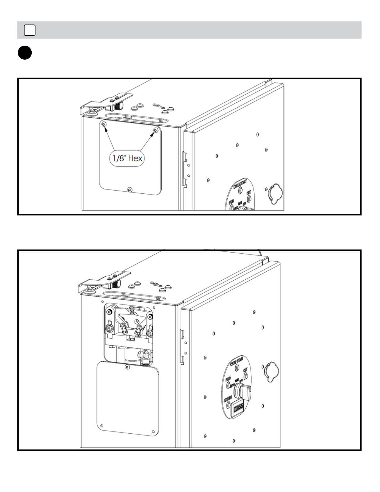
4Loading Bands
Use a 1/8" hex key to remove the (2) socket head screws and turn the safety shield
down temporarily.
1
Page 7 Oyster Banding Machine
Make sure the compressed air is on and the regulator is at 75 psi.
2
Load the tubing into the funnel.
3
Push the tubing all the way through the funnel until you feel it stop. It should have
stopped against the feed wheel. Hold the band tubing in place keeping some
pressure against the feed wheel.
4
Press the "FEED" button on the the control panel until you feel the feed wheel
engage and apply pressure, pulling the tubing. Make sure to not press "FEED" more
than 1-2 times after you feel it pull the tubing.
5
If it does not engage and pull the tube after a few attempts, see step 7a. If it
engages, continue to step 8.
IMPORTANT!
2020.09 Page 8
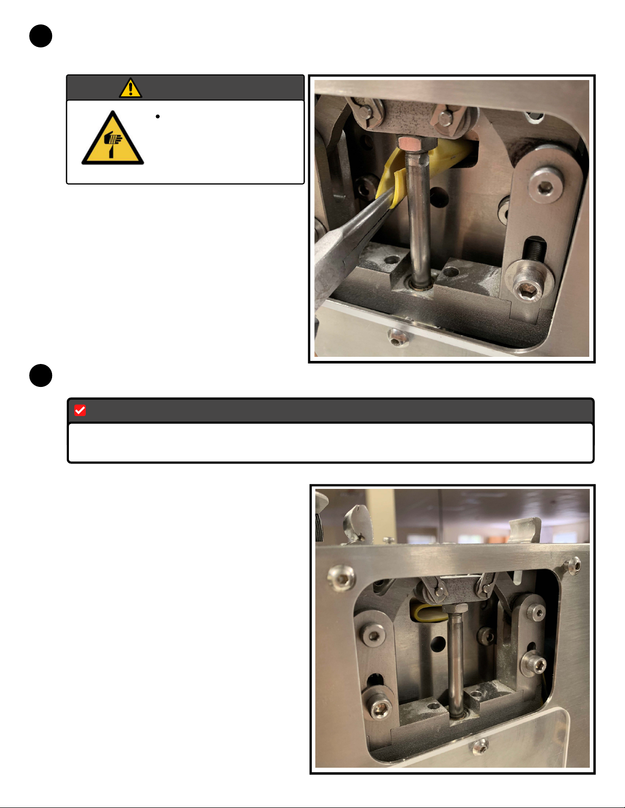
Look through the window on the side of machine where the safety shield was located.
Press FEED 1-3 more times until you see enough tubing to grab with pliers.
6
While pulling the tubing towards the window, make sure that it is fully through the
feed wheel.
7
MAKE SURE THE PLIERS ARE NOT IN THE PATH OF THE KNIFE BLADE ONCE
COMPLETE.
IMPORTANT!
Press the "CUT" button on the control panel to cut the band.
DO NOT PLACE
ANY APPENDAGES
IN PATH OF KNIFE
BLADE
Caution
Page 9 Oyster Banding Machine
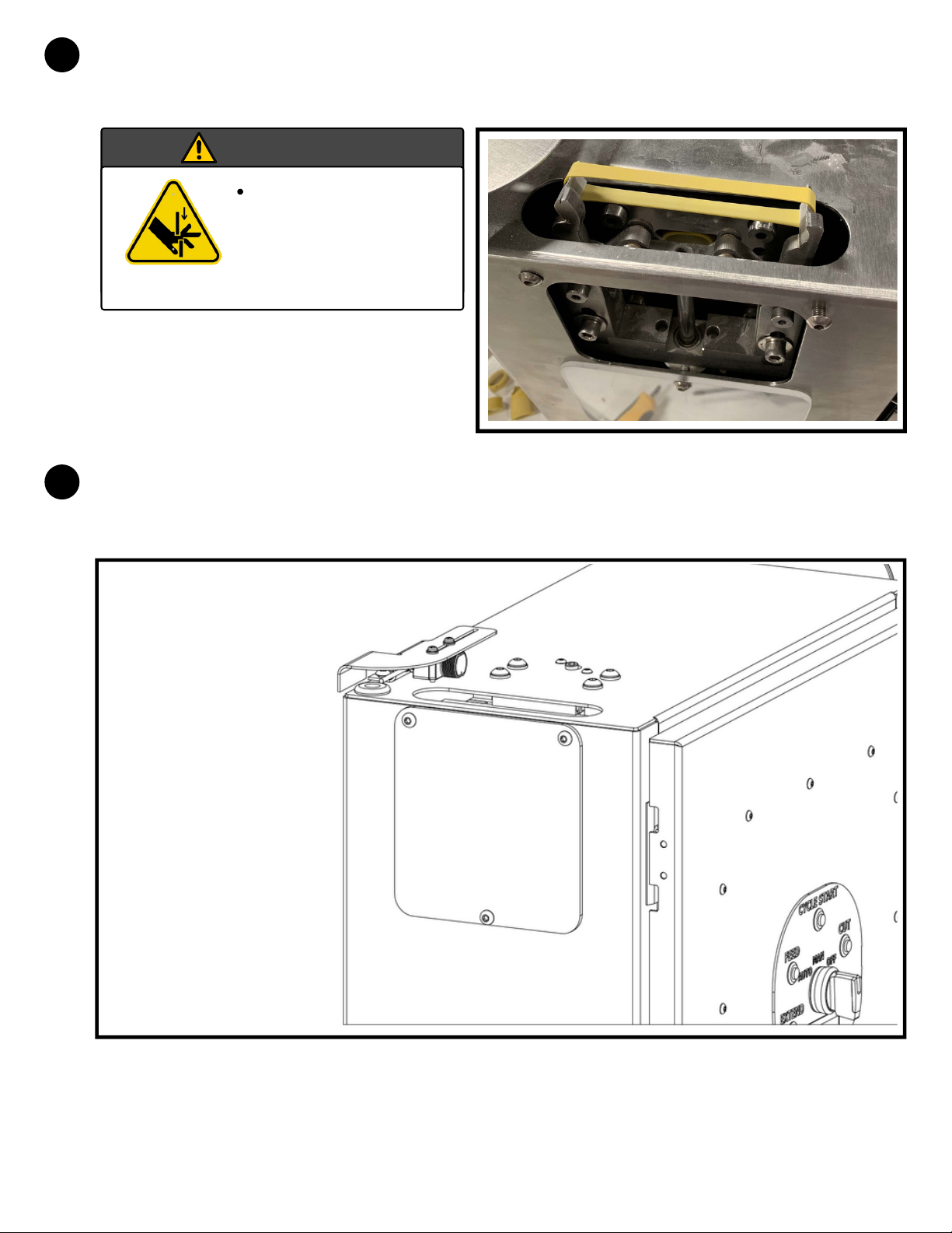
Turn the switch on the control panel to "AUTO" and then press the button labeled
"CYCLE START" or trigger the sensor until a band is loaded onto the fingers.
8
Finish by turning the safety shield and fastening the (2) socket head screws back into
place. You are now ready to start auto loading of bands.
9
DO NOT PLACE
ANY APPENDAGES
IN PATH OF
FINGERS
MECHANISM
Caution
2020.09 Page 10

5Functions: Auto Mode ("AUTO")
Flip the switch on the control board to "AUTO".
1
KEEP ALL GUARDS AND COVERS IN PLACE AT ALL TIMES
IMPORTANT!
Cycle Start:
This button will initiate a full cycle of RETRACT, FEED, CUT, and EXTEND to prepare
for the automatic feeding function.
Auto Mode:
While the switch is turned to AUTO, the sensor can be utilized for control of the
machine without touching the control panel. When an object is detected by the
sensor and then moved out of the sensor's line of sight, a new band will be loaded
into the fingers and ready for the next object. See page 16 to change the AUTO
sequence.
Place object to be banded inside the stretched band.
A
To use this mode, you must follow the following procedure:
Page 11 Oyster Banding Machine

BMove the object through the sensor's line of sight where you pass all the way
through (start in sensor's line of sight, then move out of sensor's line of sight) to
enact the sequence and automatically set up the next band.
Sensor
2020.09 Page 12
1
2
3
10
To adjust the sensor for different lengths of objects being banded, loosen the
shown screws with the tools listed and adjust accordintly.
NOTE:
To unload tubing, simply pull the tubing from the funnel side of the machine until it
comes back out from where it was fed in.
Unloading Tubing
DO NOT STAND INLINE WITH TUBING IN THE MACHINE WHEN UNLOADING
BANDS, AS THE TUBING COULD EXIT THE MACHINE QUICKLY WITH FORCE
AND CAUSE AN INJURY TO A BODY.
CAUTION:
6
Page 13 Oyster Banding Machine

7General Maintenance of Machine
Cleaning:
A typical occurrence of these machines is to have a large buildup of talc within the
whole assembly. To clean this powder from the machine, make sure to disconnect
power/air. For cleaning, it is recommended to use compressed air with safety
glasses and gloves. Be sure to clean the feed tube, inside the main enclosure,
around the knife blade, the feed wheel, and idler wheel. Please see diagrams if you
do not know where any of these components are located.
Oil:
In order for the knife blade to function properly, hydraulic oil is used and fed onto
the knife blade. The lubricator is located in the main enclosure and must be
refilled periodically. The amount of lube is set at the factory, but the oiler can be
adjusted based on what the end user sees in operation. Too much oil is better
than not enough. A bowl of oil will last roughly the consumption of one 15# reel of
tubing. Only use ISO VG 32 Hydraulic Oil. (Operating temperature of this oil
is18F/-8C to 147F/64C)
Air Filter:
Contact the manufacturer for detailed instructions on how to replace filter,
though this is generally not considered to be a maintenance item with proper
filtration on the compressor side.
*Replacement oil can be ordered from Alliance Rubber Company.
2020.09 Page 14
8Technical Instructions and Troubleshooting
If tubing is pulling through the feed wheel, but no tubing is coming out:
Tubing Not Feeding
STOP feeding.
Turn off the compressed air, unhook the quick connect coupling, or open the
main enclosure door to release back pressure in the system.
Disengage the feed wheel using the feed adjustment screw.
Pull tubing out in typical unloading situation.
Re-engage the feed wheel using the adjustment screw.
Feed tubing and look to make sure the tab cutout, as instructed in "Loading
Bands", is between the feed wheel and idler wheel.
Make sure to grab with pliers and pull through.
If tubing is not being pulled through the feed wheel:
Check on the regulator that pressure is at 75 psi.
Check and make sure the adjustment screw on the top of the machine is
engaged properly.
Check and make sure that you have cut a tab into the tubing as instructed in
"Loading Bands."
Check for a build up of talc on the feed wheel and idler wheel.
Check that the band tubing is not tangled or caught on the funnel.
Not grabbing with pliers to pull through while continually feeding. This can
lead to clogs.
TYPICAL CAUSE:
Adjusting Length of Band
Open enclosure and locate stroke limiter (item 46) on Core Assembly.
Reference page 24.
Loosen the set screw (item 17) on Core Assembly. Reference page 24.
The stroke limiter is threaded onto the feed piston.
Moving the brass stroke limiter upwards will shorten the stroke and
therefor decrease the length of band.
Moving the brass stroke limiter downwards will increase the stroke and
therefor increase the length of band.
Clog in the Feed Tube or Feed Wheel
Turn off the compressed air, unhook the quick connect coupling, or open the
main enclosure door to release back pressure in the system.
Make sure the feed wheel is disengaged by tightening the adjustment screw.
Unload band tubing in usual unloading circumstances. Apply extra pressure if
needed until tubing comes out.
Page 15 Oyster Banding Machine

Operating Settings
To decrease the speed of a cycle:
Speed Adjustment
Turn control switch into MANUAL mode
Hold CYCLE START and then press EXTEND
Switch to AUTO mode
Press CYCLE START button
To reset the speed back to default mode:
Turn control switch into MANUAL mode
Hold CYCLE START and then press FEED
Switch to AUTO mode
Press CYCLE START button
CYCLE Switch Adjustment
Turn control switch into MANUAL mode
Hold CYCLE START and then press RETRACT
Switch to AUTO mode
Press CYCLE START button
To switch to a normally closed switch (for example, a foot pedal switch):
Turn control switch into MANUAL mode
Hold CYCLE START and then press CUT
Switch to AUTO mode
Press CYCLE START button
To reset the switch to the default normally open switch (proximity sensor):
2020.09 Page 16

Bill of Materials
Item Part Number Qty.
1
2
3
4
5
6
7
8
9
10
11
12
13
14
15
16
17
18
BM1-0001-0032 NC1 Sensor Z Bracket
BM1-0001-0041 NC Enclosure
BM1-0001-0061 NC NC Cover
BM1-0001-0084 NC Locking Grommet
BM1-0001-0086 NC Grommet
BM1-0001-0087 NC Grommet
BM1-0001-0091 NC Sensor
BM1-0004-0011 NC Male Quick Disconnect
BM1-0004-0012 NC FRL Assembly
BM1-0004-0014 NC Connector, Tubing
BM1-0005-0016 NC 5 Pos. Male Receptacle
BM1-0002-0041 NC Infeed Funnel
M3.0-.50 Nut, Hex
M3.0-.50 X20.00 18-8 SS Screw, Pan-Head Philips
#4 18-8 SS Washer, Internal Tooth
1/4-20 St Stl Nut, Self-Locking
1/4-20 X0.75 St Stl Screw, Button-Head Socket
10-32 X0.375 St Stl Screw, Button-Head Socket
2
1
1
1
1
1
1
1
2
1
2
1
2
2
2
2
2
5
ENCLOSURE
ASSEMBLY:
Exterior
Page 17 Oyster Banding Machine
Table of contents
Popular Food Saver manuals by other brands


Teknika
Teknika MUL-331 Operation manual

Signode
Signode B-250 Operation, parts and safety manual

3M
3M 3M-Matic 700r3 Instructions and parts list

BJS Biotechnologies
BJS Biotechnologies xxsealer user manual

Thermopatch
Thermopatch HS-4-C user manual

Infinity Solutions
Infinity Solutions 7K Plus Service manual


