Infinity Solutions 7K Plus User manual

Infinity Solutions Manufacturing
192 Gannett Drive South Portland, ME 04106
(207) 899-1714
7K Plus Service Manual

ii

iii
Table of Contents
Table of Contents ..............................................................................................................................................iii
Service Manual Notes.........................................................................................................................................v
Tools Needed.....................................................................................................................................................................v
Parts:..................................................................................................................................................................................v
Technical Help ...................................................................................................................................................................v
Additional Notes.................................................................................................................................................................v
1. Machine Overview ..........................................................................................................................................6
1.1. Covers.........................................................................................................................................................................7
2. Drive Train.......................................................................................................................................................8
2.1. Conveyor Drive Pulley & O-Ring ................................................................................................................................8
2.2. Drive Motor: Belt, Pulleys, and Clutch........................................................................................................................9
2.3. Gears ..........................................................................................................................Error! Bookmark not defined.
2.4. Double Sided Timing Belt and Drive Pulleys............................................................................................................11
3. Feed Table.....................................................................................................................................................12
3.1. Feed Table................................................................................................................................................................12
3.2. Feed Drive Belts .......................................................................................................................................................13
4. Feed Gauge...................................................................................................................................................14
5. Nip Wheel ......................................................................................................................................................15
6. Conveyor.......................................................................................................................................................16
6.1. Extended Conveyor Belts .........................................................................................................................................16
6.2. Conveyor Belts............................................................................................................Error! Bookmark not defined.
7. Wiper..............................................................................................................................................................17
8. Rolls...............................................................................................................................................................18
9. Electrical........................................................................................................................................................20
9.1. Drive Motor ...............................................................................................................................................................20
9.2. Touch Screen............................................................................................................................................................20
9.3. PLC...........................................................................................................................................................................21
9.4. Power Supply............................................................................................................................................................21
9.5. Motor Drive ...............................................................................................................................................................21
9.6. Doubles Detection.....................................................................................................................................................22
9.6.1 Optic Cable..........................................................................................................................................................................22
9.6.2 Optic Amplifier......................................................................................................................................................................22
9.6.3 Sensor Alignment.................................................................................................................................................................23
9.6.4 “Teaching” the Optic Amplifier..............................................................................................................................................23
9.7. Feed Counter............................................................................................................................................................23
10. Troubleshooting .........................................................................................................................................24
10.1. Machine Will Not Power On....................................................................................................................................24
10.2. Machine Powers On But Will Not Run....................................................................................................................24
10.3. Machine Stops Running..........................................................................................................................................25
10.4. Paper Jams.............................................................................................................................................................25
10.5. Improper Functioning of the Machine.....................................................................................................................26

iv
10.5.1 Misaligned Folds................................................................................................................................................................26
10.5.2 Paper Feed Problems........................................................................................................................................................26
10.5.3 Dirty forms..........................................................................................................................................................................27
10.5.4 Motor Runs only in one direction........................................................................................................................................27
10.5.5 Erratic speeds......................................................................................................................Error! Bookmark not defined.
10.5.6 Excessive Noise.................................................................................................................................................................27
10.5.7 Poor Stacking.....................................................................................................................................................................27
10.6. Sensors...................................................................................................................................................................27
10.6.1 Doubles Detection..............................................................................................................................................................27
10.6.2 Reflective Counter Sensor.................................................................................................................................................28
10.6.3 Door Switch........................................................................................................................................................................28
10.6.4 Fold Plate Switch ...............................................................................................................................................................28
10.7. Electronic Components...........................................................................................................................................30
10.7.1 Touch Screen.....................................................................................................................................................................30
10.7.2 Power Supply.....................................................................................................................................................................30
10.7.3 PLC....................................................................................................................................................................................30
10.7.4 Driver .................................................................................................................................................................................30
10.7.5 Drive Motor ........................................................................................................................................................................30
11. Appendix .....................................................................................................................................................31
12. Addendums………………………………………………………………………………………………………….31

v
Service Manual Notes
Tools Needed
• Set of standard Inch Allen Wrenches
• 7/16” Deep Socket & Driver
• 1 ¼ “ Socket
• Torque Wrench, with 12 ft*lbs capabilities
• Philips head Screw Driver
Parts:
For parts please contact Infinity Solutions Manufacturing:
Phone: (207) 899-1714
Fax: (207) 228-1890
www.infinitysolutionsmfg.com
Part numbers are included for components shown in exploded views through out the manual and in the
appendix.
Technical Help
The majority of service operations are covered in this manual. However, if you are unable to resolve a
problem please contact technical support at Infinity Solutions Manufacturing.
Phone: (207) 899-1714
Additional Notes
This manual is for use with the Infinity Solutions 7K plus.
6
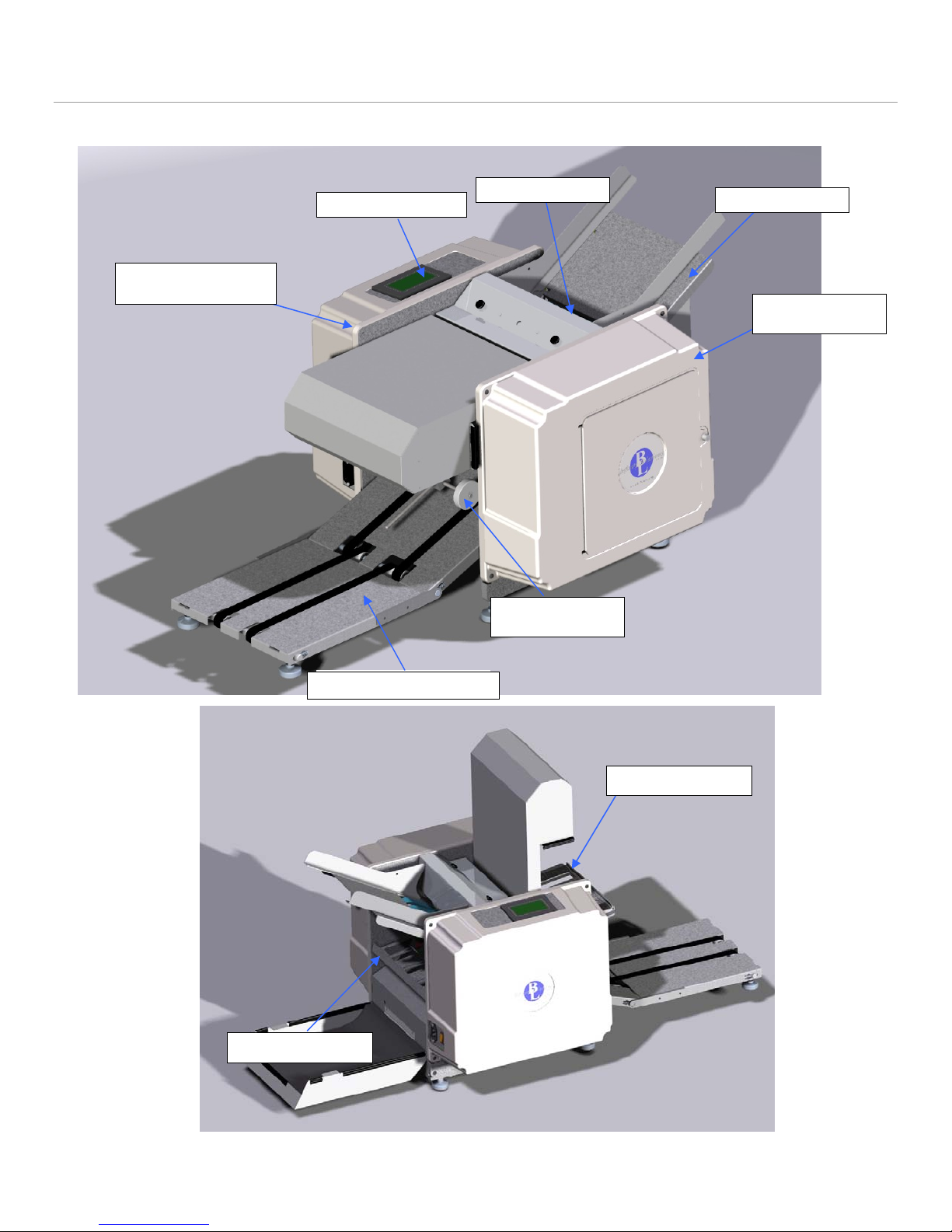
1. Machine Overview
•Read the operators manual to become familiar with the machine operation.
Feed Gauge
Electrical Side
Cover
Control Panel
Motor Side
Cover
Conveyor Nip
Wheels
Feed Table
Extended Conveyor
Lower Fold Plate
Upper Fold Plate
Figure 1: Overview

7
1.1. Covers
a) Removal
1. Remove the cover screws (4x).
2. Slide the cover off the machine.
b) Installation
1. Installation is the reverse of removal.
Cover
Power Switch / Breaker
Power Cord Plug
Figure 2: Power Connection and Switch
Figure 3: Covers
Cover Screw (4x)

8
2. Drive Train
2.1. Conveyor Drive Pulley & O-Ring
a) Removal
•Disconnect the power cord from the machine.
1. Remove the drive train side cover.
2. Roll the o-ring off of the conveyor pulley.
3. Remove the conveyor pulley.
a)Loosen the set screw.
b)Pull the pulley off of the shaft.
b) Installation
1. Place the conveyor pulley onto the shaft with the hub on the
inside.
2. Align the O-Ring grove in the pulley with the O-Ring grove on the roll shaft.
Figure 4: Drive Train
Note: if motor belt is marked 5M450 15, then see addendum
Motor Pulley and Clutch
Feed Drive
Pulley
Motor Belt
28-0832-00
Door Switch
Double Sided Belt
Conveyor Pulley
Roll Gears
Feed Pinion
Pulley
Feed Drive
Belt
O-Ring
Figure 5: Conveyor Drive
9
Note: The conveyor pulley is mounted on a floating shaft and the pulley will self align itself, however is best if they
are closely aligned to begin with. Tighten the set screw
3. Roll the o-ring onto the conveyor pulley.
4. Ensure the o-ring or pulley can not contact any other drive train components.
Note: For conveyor pulley and O-ring part #’s see the Appendix. If existing pulley does not have shown hub,
then the clear o-ring must be used. Otherwise, the black one is needed.
2.2. Drive Motor: Belt, Pulleys, and Clutch
a) Removal
•Disconnect the power cord from the machine
1. Loosen all four motor screws and slide the drive motor forward to loosen the belt tension.
2. Slide motor belt off of the motor pulley.
3. Remove the motor clutch and pulley.
a)Loosen set screw.
b)Pull the motor clutch and pulley off of the motor shaft.
Note: If the motor pulley needs to be removed from the clutch,
remove the set screws, the large center nut on the clutch and
disassemble. To break the nut loose reinstall the belt, place a
socket driver on the end of the hex shaft and loosen the center
nut on the clutch. Alternately, if the clutch is already removed,
the inside can be placed in a vise and the center nut can be
loosened.
4. Remove the roll drive pulley.
a)Loosen both the set screws.
b)Slide the pulley off of the shaft.
b) Installation
1. Install the roll drive pulley onto the roll shaft with hex end. Ensure the drive key is properly placed in the
keyway. Butt the pulley up with the coinciding pulley on the shaft and tighten both set screws.
2. Install the motor clutch and pulley onto the motor shaft. Ensure the drive key is properly placed in the
keyway. Note that an undersized 3/16 key is used.
3. Slide the belt onto the pulleys. Align the motor clutch and pulley on the motor shaft so that the belt rides on
the middle of the pulley. Tighten the set screw.
4. Adjust the belt tension (See Section 2.2.c)
5. Check for clearance of the belt between nearby pulleys and ensure there will be no interference. If any
interference is found realign pulleys.
c) Adjustments
Belt Tension
1. With the motor mounting screws loose, slide the drive motor back until the belt is taut. Tighten the motor
mounting screws.
Motor Clutch Adjustment
The motor clutch must be adjusted if:
(i) Being replaced
(ii) The motor pulley has been removed from the clutch
(iii) The center nut on the clutch has been loosened or
tightened.
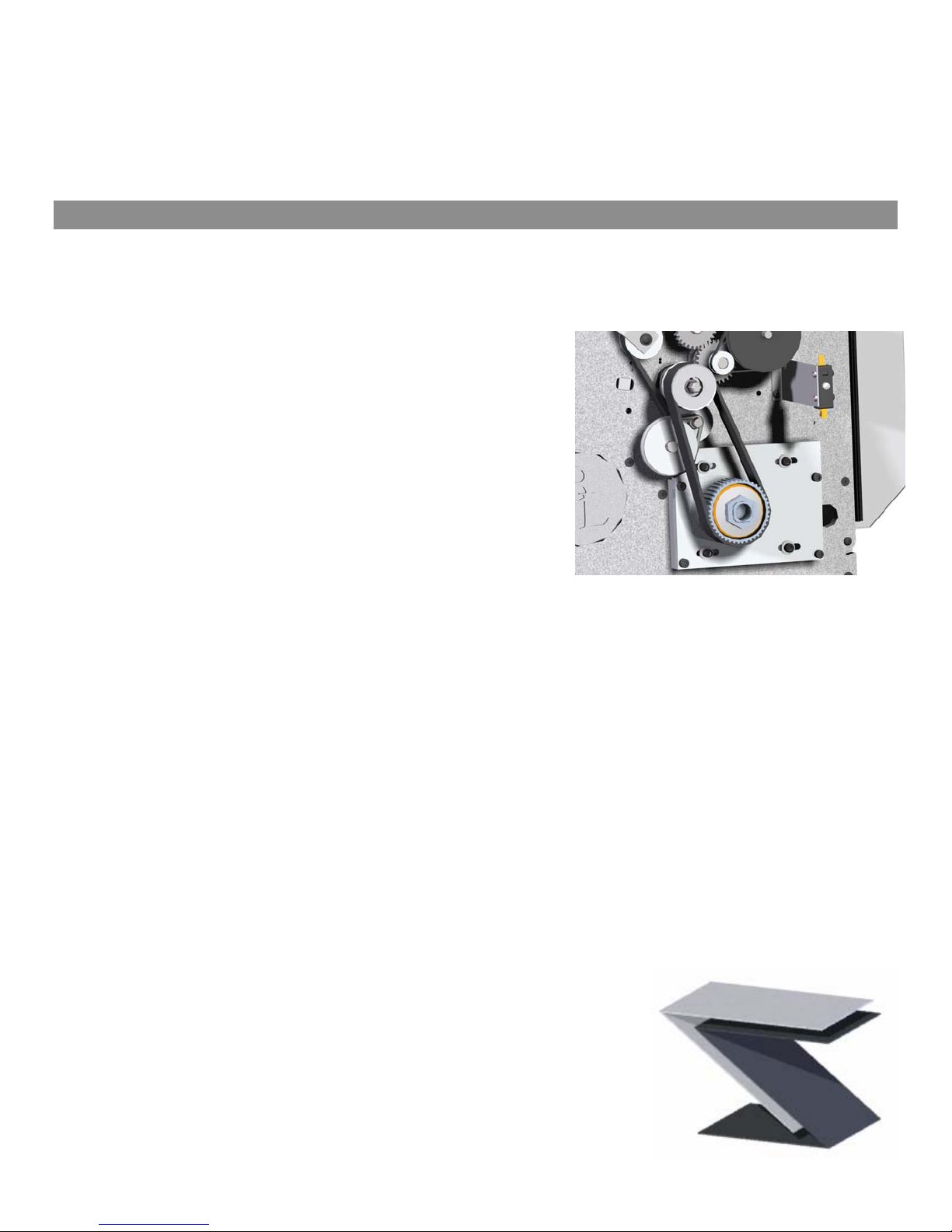
Figure 7: 1 and 2/3 forms
folded together
Figure 6: Drive Motor System

10
Note: If improperly adjusted premature component failure or poor machine performance can occur.
1. Use a torque wrench to tighten the center nut of the clutch to 12 ft/lbs.
2. With the drive train completely assembled and all protective guards in place plug in the machine and power it
on.
3. Test the adjustment by running a 1 2/3 folded form (See Figure 7) through the back of the machine while it
runs at full speed (See Figure 8 ).
a)To feed the form into the back of the machine, remove the rear fold plate. The fold plate switch will have to
be depressed to run the machine in the forward direction.
b)The form should make it through with minimal slipping of the motor. Note: by listening to the motor you
will be able to hear if it slips. If the form does not make it through the machine then the clutch is too loose:
tighten the clutch and repeat.
4. To determine if the clutch is too tight run two forms folded together through the back of the machine. The
paper should not make it through the machine, however the clutch should slip. You will be able to briefly hear
this just as the motor shuts down. If the clutch does not slip at all loosen the center nut.
5. Repeat steps 3 and 4 until both above criteria are met.
Note: If pulley material is aluminum, then see addendum
Figure 9: Motor Clutch Exploded View
Figure 8: Back of the Machine
Insert folded form Here
for clutch adjustment

11
2.3. Double Sided Timing Belt and Drive Pulleys
a) Removal
•Disconnect the power cord from the machine.
1. Remove the conveyor pulley, motor belt and the gears. (See Section 2.2)
2. Remove the double sided belt.
a)Loosen the idler tension bracket and slide the bracket and pulley down to release tension on the belt.
b)Remove the idler pulley from the bracket.
Note: The pulley uses a double screw attachment and both sides must be held to unscrew the screws.
3. Remove the roll pulleys.
a)Loosen the set screws and remove the pulleys.
4. Remove the belt.
b) Installation
1. Installation is the reverse of removal.
12
2. Adjust belt tension. (See Section 2)
c) Adjustments
1. With the idler bracket loose, slide the idler wheel and bracket up until the belt is tight. Tension the belt so
that the belt and gears move freely with minimal resistance. If the belt is too loose excess noise and
premature belt failure can occur.
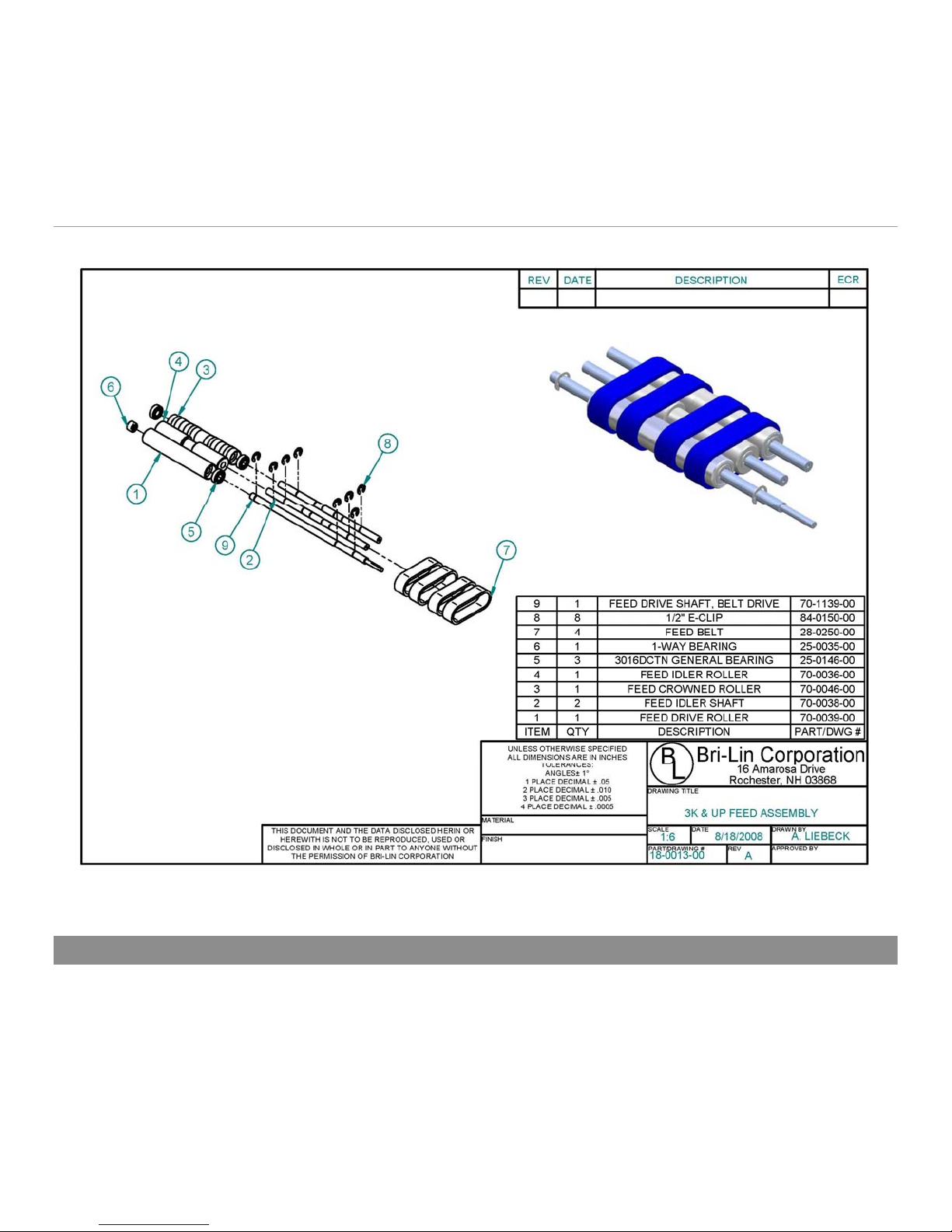
3. Feed
Figure 10: Feed Assembly
3.1. Feed Table
a) Removal
•Disconnect the power cord from the machine.
1. Remove both the side covers.
2. Remove the feed pulleys and belt.
3. Remove the feed table screws, 2x per side (4x total). (See Figure 19)
4. Remove the feed table.

13
b) Installation
1. Installation is the reverse of removal.
3.2. Feed Drive Belts
a) Removal
•Disconnect the power cord from the machine
1. Remove the E-clips from the drive shaft (4x).
2. Remove shaft support screws from the side frames. (See Figure 19)
3. Slide the drive shaft through the drive train side frame.
4. Pull the idler shafts out the back side of the chassis.
5. Remove the belts.
a)Inspect the belts for any wear or damage. If any is found replace the belts.
b) Installation
1. Place the idler rollers onto the idler shafts and place the belt around the rollers.
a)Insert the drive roller inside the belts. (Note: ensure that
the 1-way bearing is positioned on the side closest to the
electrical side frame)
b)Insert the idler shafts, rollers and belts into the chassis and
insert shaft screws into the side frame.
Note: The crowned roller goes to the back of the machine. (See
Figure 10)
2. Insert the drive shaft through drive train side frame, insert the
shaft into the drive roller as the shaft is being inserted into the
side frame.
3. Replace the E-clips (4x).
4. Ensure belts are aligned and are oriented with the blue side
visible.
5. Reinstall feed pulleys and belt.
c) Adjustment
Paper Feed Tray Width Adjustment
Place a squared up stack of the paper to be used into the tray and align the paper to the fixed side of the tray.
Adjust the sliding side so that there is approximately 1/8 inch between the stack of paper and the guide. If there is
no gap the paper may bind and not feed; if too loose paper may feed crooked.
Fi
g
ure 12: Feed Rollers and Belts

14
4. Feed Gauge
Figure 11: Feed Gauge Assembly
a) Removal
•Disconnect the power cord from the machine.
1. Remove the feed gauge cover.
2. Remove both side covers.
3. Remove the x-tie screws from both side frames.
(See Figure 19)
4. Pull the feed gauge assembly up and out of the
machine.
Note: If the x-Tie is too tight in the chassis to remove it
maybe necessary to loosen the feed table, feed idler
shafts, conveyor, sensor x-tie, and front & rear
motor guard screws on the motor side frame. (See
Figure 19)
b) Installation
1. Assembly is the reverse of the removal.
2. Adjust the feed gauge.
c) Adjustment
•Disconnect the power cord from the machine.
1. Remove feed gauge cover
2. Place 1 form on the feed table and hand feed the form into the machine by moving the feed belt with your
hand.
3. Pull the paper out of the machine. You should feel resistance, but not too much. Turn the adjustment screw
clockwise for less resistance and counter-clockwise for more resistance.
Figure 12: Cross-section of Feed Gauge
Adjustment Screw

15
5. Nip Wheel
ITEM PartNo DESCRIPTION QTY.
1 70-0070-00 Nip Wheel Caster 1
2 70-0071-00 Nip Wheel Block 1
3 70-0072-00 Nip Wheel 2
4 70-0073-00 Nip Wheel T-Hinge 1
5 80-0165-00 Shoulder Screw, 1/4" x 5/8" x #10-24 2
680-0188-00 Set Screw, SSS #10-32 x 1/4" 1
784-0065-00 Red #10-32 Thumb Screw 1
884-0161-00 E-Clip, 1/4" Shaft, .025" Thick 4
984-0272-00 Mylar Velvet 1
54
1
7
6
2
8
3
9
Bri-Lin Corporation
16 Amarosa Drive
Rochester, NH 03868
B
L
DRAWING TITLE
PART # REVISION DRAWN BY
DRAWING # SCALE DRAWING DATE
18-0105-00
MD-0105-00
A
1/11/2005
MATERIAL
FINISH
UNLESS OTHERWISE SPECIFIED
ALL DIMENSIONS ARE IN INCHES
TOLERANCES:
ANGLES 1
1 PLACE DECIMALS .05
2 PLACE DECIMALS .010
3 PLACE DECIMALS .005
4 PLACE DECIMALS .0005
1:3
THIS DOCUMENT AND THE DATA DISCLOSED HERIN OR
HEREWITH IS NOT TO BE REPRODUCED, USED OR DISC-
LOSED IN WHOLE OR IN PART TO ANYONE WITHOUT THE
PERMISSION OF BRI-LIN CORPORATION
NOTE: Static Brush Part #55-0388-00 not shown
Figure 13: Nip Wheel
a) Removal
•Disconnect the power cord from the machine.
1. Remove both the side covers.
2. Remove the x-tie screws from both side frames.(See Figure 19)
3. Slide the nip wheel assembly out of the front of the machine.
b) Installation
Installation is the reverse of the removal.
c) Adjustment
Note: The nip wheel should be adjusted every time a new fold or
form is used that yields a different final size.
1. Set the form with desired fold onto the conveyer so that it is
touching the edge of the roll.
2. Adjust the nip wheel so that it is ½” from the other side of the
folded form. (See Figure 14)
Figure 14: Nip Wheel Adjustment
Folded
Form
Roll
Nip
Wheel
NIP WHEELS MAY NOT BE
WHITE
16
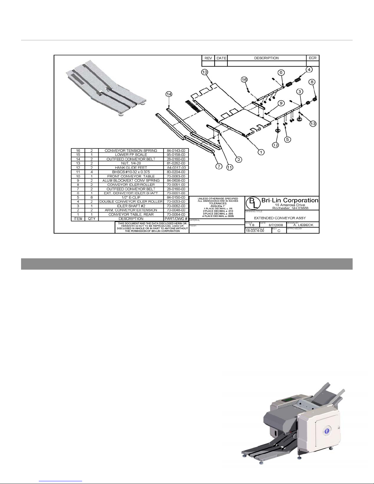
6. Conveyor
Figure 15: Extended Conveyor
6.1. Extended Conveyor Belts
Note: Only the 7K Plus is equipped with the extended conveyor, the 7K is equipped with the standard conveyor which
does not contain the additional conveyor table and belts.
a) Removal
•Disconnect the power cord from the machine.
1. Remove the E-clips on both the idler shafts (8x).
2. Remove the springs from both idler shafts.
Note: Different size springs are used for the intermediate idler shaft and for the final idler shaft.
3. Remove the feet from the final idler shaft.
4. Slide and orient the final idler shaft in table slot to allow for removal and slide the shaft out of the table.
5. Remove the extended conveyor arm from one side of the
extended conveyor.
6. Slide and orient intermediate idler shaft in the table slot
to allow for remove and then slide it out of the table.
7. Remove the conveyor belts.
b) Installation
1. Place the conveyor belts around the rolls on both
conveyor tables.
2. Place the extended table near the conveyor table and
insert the intermediate shaft into the table, making sure
Figure 16: Conveyo
r

17
that the belts for the extended conveyor are on the pulleys.
3. Reattach extended conveyor arm.
4. Orient the shaft such that the bore for the spring is aligned with the notch for the spring, insert springs.
5. Insert E-Clips onto the intermediate idler shaft (4x).
6. Place and hold the final idler rollers inside the extended conveyor belt.
7. Slide the final idler shaft in place.
8. Insert E-Clips (4x).
9. Orient the shaft such that the bore for the spring is aligned with the notch for the spring, insert springs.
10. Reattach the feet so that the conveyor table sits evenly.
7. Wiper
3
2
1
Bri-Lin Corporation
16 Amarosa Drive
Rochester, NH 03868
B
L
DRAWING TITLE WIPER ASSEMBLY
PART # REVISION DRAWN BY
DRAWING # SCALE DRAWING DATE
18-0219-00
MD-0219-00
A
1/11/2005
AAS
MATERIAL
FINISH
UNLESS OTHERWISE SPECIFIED
ALL DIMENSIONS ARE IN INCHES
TOLERANCES:
ANGLES 1
1 PLACE DECIMALS .05
2 PLACE DECIMALS .010
3 PLACE DECIMALS .005
4 PLACE DECIMALS .0005
1:1.5
THIS DOCUMENT AND THE DATA DISCLOSED HERIN OR
HEREWITH IS NOT TO BE REPRODUCED, USED OR DISC-
LOSED IN WHOLE OR IN PART TO ANYONE WITHOUT THE
PERMISSION OF BRI-LIN CORPORATION
ITEM PartNo DESCRIPTION QTY.
170-0220-00 Felt Holder 1
270-0221-00 Wiper Felt Strip 1
384-0164-00 Black #10-32 Thumb Screw 3
Figure 17: Wiper Assembly
a) Removal
1. Remove all three thumb screws.
2. Slide the wiper assembly off the x-tie and remove from the machine.
3. Inspect the felt wiper, if it is dirty flip over or replace.
b) Installation
1. Slide the wiper assembly in place.
2. Insert the two thumb screws facing out the front of the machine.
3. Adjust the pressure on the roll so the felt is slightly touching. Check that the holder is parallel with the roll.
Note: If the felt is pressing too hard on the roll it can increase the load on the motor and reduce the performance
of the machine. If the felt is not contacting the roll it will not properly clean and can mark up the forms with ink.
4. Insert the last thumb screw into the top of the felt holder.

18
8. Rolls
Note: If roll configuration is different than shown, see addendum
Figure 18: Rolls
a) Removal
•Disconnect the power cord from the machine.
1. Remove the all drive train components. (See Section: 2)
2. Remove the fold trays, simply lift up trays and slide out of chassis.
3. Remove the feed gauge x-tie mounting screws from the drive train side of the chassis. (See Figure 19)
4. Remove the feed table mounting screws from the drive train side of the chassis. (See Figure 19)
5. Remove the feed roller mounting screws from the drive train side of the chassis. (See Figure 19)
6. Remove the conveyor table mounting
screws from the drive train side of the
chassis. (See Figure 19)
7. Remove the nip wheel x-tie mounting
screw from the drive train side of the chassis.
(See Figure 19)
8. Remove the drive motor guards and the
drive motor mounting screws. The drive
motor can be left in the machine.
9. Ensure the electrical side cover is in place
and on a sturdy surface tip the machine so
that the electrical side is face down. Ensure
the drive motor is securely resting and no
wires are being pinched or stretched.
10. Remove the base plate mounting screws
and rear leg from the drive train side frame.
11. Slide the drive train side frame off of the
rolls and remove. SERVICING THE ROLLS

19
12. Inspect the rolls for wear and replace any damaged or worn components.
a)Clean rolls by wiping down with a household cleaner such as OOPS or the equivalent.
b) Installation
1. Installation is the reverse of removal
Figure 19: Side Frame Screws
This view is shown with roller bearings
Note: If Frames are not as shown, see addendum
RollerBearing NeedleBearing
Part # 25-1103-00 Part # 25-0167-00
BEARING IDENTIFICATION
Feed Gauge X-tie
Conveyor Table
Feed Idler Shafts
Rear Motor
Guard
Front Motor Guard
Feed Table
Drive Motor (4x)
Cover (4x)
Nip Wheel X-Tie
20
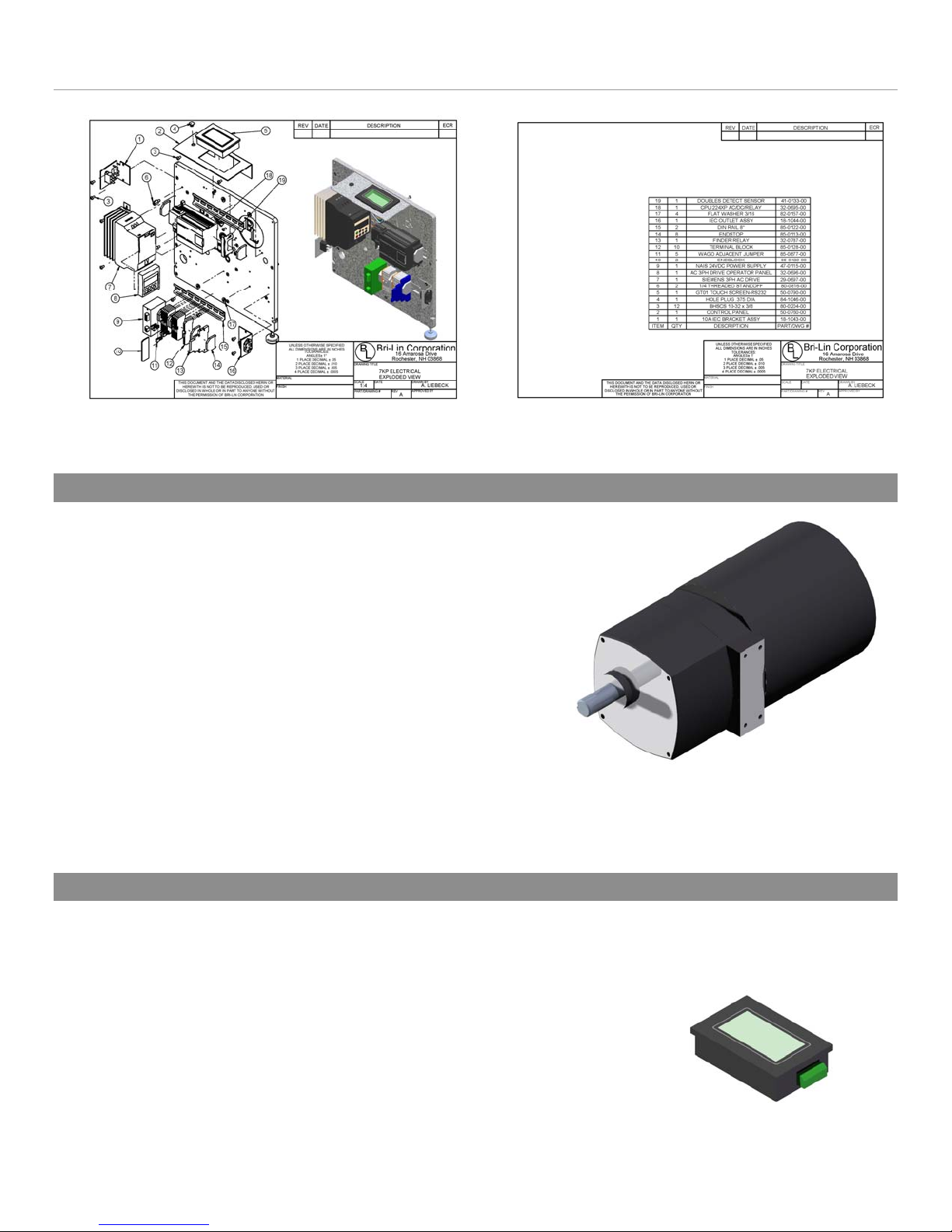
9. Electrical
Figure 20: Electrical Components (Optional Fuji Drive not shown #29-0697-00)
9.1. Drive Motor
a) Removal
•Disconnect the power cord from the machine
1. Remove both the side covers.
2. Remove the rear motor guard.
a)Unscrew the power switch bracket from the electrical
side frame.
b)Unscrew and remove the rear motor guard.
3. Disconnect the electrical leads from the motor.(See
Appendix)
4. Remove the motor clutch with pulley. (See Section 2.2)
5. Remove the motor mounting screws and slide the
motor from the chassis.
b) Installation Motor Part #30-0658-00
1. Installation is the reverse of the removal.
9.2. Touch Screen
a) Removal
•Disconnect the power cord from the machine.
1. Remove the electrical side cover.
2. Remove the small holding brackets (4x).
3. Unplug the electrical connector from the unit.
4. Remove the touch screen and if faulty replace with a new
unit.
Table of contents
Other Infinity Solutions Food Saver manuals


Popular Food Saver manuals by other brands


Pro-Line Boats
Pro-Line Boats VS-CHD2 user manual

FoodSaver
FoodSaver Vacuum Sealing System user manual

ACME
ACME DSR-220 Operation, parts and safety manual

IPG
IPG INTERPACK USA 2024-BFF Operations manual & parts list

3M
3M 3M-Matic 7000r-I Instructions and parts list

Lava
Lava V.300 Premium operating instructions