STS M2-D922 User manual

Surface to Surface Inc. ®
Operators Manual
** M2-D922 **
USE IN CONJUNCTION WITH OEM MANUALS (ENCLOSED)
Unit Serial No. _______________
Yanmar Engine
L100V – Serial No. ______________
Gorman-Rupp® Pump
STS-GR82E2 – Serial No. ________________
Links relating to this Manual
www.stsmixers.com
www.yanmar.com
www.grpumps.com
STS-106 Rev. 08/20/21 www.stsmixers.com
Dealer

2
This page left blank intentionally

3
TABLE OF
CONTENTS
PAGE
STS Inc. Warranty…………………….….……………………………….. 6
Safety Statements………………………………………………...………… 7-10
Safety Markings……………………………………………………………. 11
Main Working Components (Photo)……………………………………… 12
M2-922 Hose Connections ……………….………………….……………. 13
Introduction to the M2-D922 ……………….………..………..…………. 14
M2-D922 Foot Print (top view)……………………………….…………… 15
M2-D922 General Data Sheet…………………………………………………. 16
Identifying Your Machine & Components………………………………. 17
SECTION II (Description, Care and Maintenance)
Diesel powered centrifugal pump.…….…………….………….…. 19-22
3-Way Valves …………………………………………………...……. 23
Filter shear system……………………………………………………. 24-25
Venturi mixing tee……………………………..………..……………. 26
Wash wand……………………………………………………...……. 27
Dry hopper with table & hopper valve…………………………..…… 28
Internal tank jets ……………………………………...……………… 29-30
SECTION III (Set-up and installation of unit in Detail)
Permanent mounting of unit…………………………...…………….. 32
Portable use of unit…………………….…………………….………. 32

4
TABLE OF
CONTENTS
PAGE
SECTION IV (Operating the M2-D922 Unit.
Site set-up and pre-check…………………………………………….. 34
Starting the engine driven pump…………….….…....…….……… 35
Typical mixing operation……………………….……………………. 36-37
Typical transfer / off-loading operation……………………………… 38
Shutdown, cleanup & storage
Warm weather…………………………………….…………. 39
Cold/ freezing weather………………………………….…… 40
Prolonged periods of storage………………………………… 41
Fluid Recovery Operation (basic) …………….….…….……….…….. 42
SECTION V (Trouble shooting)
Trouble Shooting the M2-922 ………….…….….….…..…….....…… 44-45
SECTION VI (Periodic Maintenance & Repair Information)
Maintenance Schedule…………………….….………………….…... 47
Centrifugal Trash Pump Seal Replacement………………………..… 48
Bolt torque Specifications…………………………………….……... 49
Notes…………………………………………………….…………… 50

5
TABLE OF
CONTENTS
PAGE
SECTION VII (OEM Repair / Information)
GR Centrifugal Pump Owner’s Manual……………………..………… 52-63
Engine Manufacture Customer Help (web-site) …………...…………. 64
Gruvloc® Pipe Couplings ………….…….….….………………..…… 65-67
SECTION VIII (Parts Manual - version 1)
M2-D922 PARTS MANUAL…………………….…………….……. 69-71
SECTION IX (Parts Manual - version 2)
MAC-JR-1200D Mixer PARTS MANUAL…………..….…..….…. 73-75

6
Limited Warranty
United States and Canada
Surface to Surface Inc. or its subsidiary which last sold the product, warrants new products sold by it for use in the
United States and Canada to be, at the time of manufacture, free from defects in workmanship and materials. This
warranty covers for a period of Twelve (12) Months of operation from the date of delivery for initial use, whichever
comes first.
Exclusions and Additional Limitations
1. This warranty relates to the condition of the product at the time of manufacture and does not cover parts or
service as a result of:
(a) Normal wear and tear or required maintenance including, without limitation, adjustments or replacement of
components subject to wear and tear, such as belts, hoses, seals and/or packing, fuses, bulbs,
switches and ignition parts.
(b) Abuse including, without limitation, neglect, improper operation, misapplication, overloading, accident or
alterations not approved by Surface to Surface Inc.
(c) Lack of maintenance, including, without limitation, failure to inspect and maintain, improper repair, use of
“unapproved parts”, cracked engine heads and blocks unless caused by the failure of
an internally lubricated part or repair of engine valves, rings or guides.
2. The Company’s warranty does not apply to purchased components manufactured by others where separate
warranty is made by the manufacture of such components and will be applied as interpreted by
the supplier.
3. All claims under his warranty shall be submitted in writing by the distributor to the Company, which will be the
sole judge in determining the merits of the claim.
4. The company shall have the right to have all products or parts claimed to be defective returned to it and the
cost of shipping such items shall be borne by the distributor.
……………………………………………………………………………………
Warranty Registration Card
In order to help us provide complete service for our product, please complete this card and return it.
If not returned, all requests for warranty will be denied.
Print Name: …………………………………………………………………….….
Address: …………………………………………………………………………...
City: ……………………State/Province………………Zip/PC…………………...
Model No. ………………………….. Serial No. …………………………………
Date of Purchase ………………………… Dealer ………………………………..
Return to: Surface to Surface Inc.
5150 Forest Rd. RR#3
Watford, Ontario, Canada
N0M 2S0
01/14/08
7
M2-D922
SAFETY STATEMENTS
Your personal safety and the safe operation of this unit are the concern of Surface to Surface Inc., and by
reading and understanding this manual and understanding the safety statements, you will decrease the risk of
personal and equipment damage.
Safety statements are listed here and throughout this manual to draw your attention to potential hazards that
may be encountered while operating this piece of equipment. While reading this manual, you will notice that
certain safety statements will relate directly to the operation, or maintenance of that particular part of the unit and
should be followed carefully. Decals on the unit also follow the same format as the warnings in this manual, and
therefore should be kept in good repair to alert the operator and others of the potential hazard.
The engine / motor manual also contains hazard warnings which pertain to the engine / motor and should
also be followed.
This safety alert symbol appears with most safety statements.
It means attention, become alert, your safety is involved!
Please read and abide by the message that follows the safety alert symbol.
DANGER
WARNING CAUTION
CAUTION
Caution "without the safety alert symbol"
indicates an potentially hazardous
situtation that can cause damage to the,
machine, personal property and / or the
environment or cause the machine to
operate improperly.
Danger (the word "DANGER" is in white
letters with a red rectangle behind it)
indicates an imminently hazardous
situation, which, if not avoided, will
result in death or serious injury.
Danger is limited to the most extreme
situations.
Warning (the word "WARNING" is in black
letters with an orange rectangle behind it)
indicates an potentially hazardous
situation which, if not avoided, could
result in death or serious injury.
Caution (the word "CAUTION" is in black
letters with a yellow rectangle behind it)
indicates an potentially hazardous
situation which, if not avoided, may
result in minor or moderate injury.
8
M2-D922
SAFETY STATEMENTS
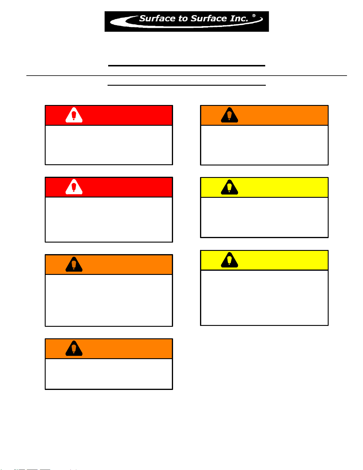
The following caution statements have been drawn from the instructions in this manual. They
have been assembled here for ready reference.
DANGER
IN AN EMERGENCY
rotate the throttle control lever to
the STOP position
to halt engine, pump, and fluid flow
DANGER
NEVER ATTEMPT REPAIRS
OR DISASSEMBLY
without shutting off the engine / motor
and disconnecting the power source.
Serious personal injury will result.
WARNING
NEVER USE BODY PARTS,
OR FOREIGN OBJECTS
in an attempt to unplug or clean the
hopper valve or mixing tee.
Serious personal injury or
damage will result.
WARNING
Serious personal injury will result.
DO NOT REMOVE OR MODIFY
SAFETY COVERS OR GUARDS.
WARNING
while the unit is in operation.
Serious personal injury will result.
NEVER ATTEMPT TO REMOVE
OR CLEAN THE FILTER SHEAR
CAUTION
DO NOT POSITION
ANY PART OF YOUR BODY
over the hopper, valve,
or mixing tee while cleaning.
CAUTION
WHEN THE UNIT
IS IN OPERATION,
the fluid in the piping may reach
pressures up to 50 p.s.i.
When the engine is idling, the system is
still pumping fluid under pressure.

9
M2-D922
SAFETY STATEMENTS continued
The following caution statements have been drawn from the instructions in this manual. They
have been assembled here for ready reference.
CAUTION
TRAPPED FLUID MAY BE PRESENT
and will spill out when piping, hoses,
pump or filter shear are removed.
CAUTION
AVOID ALLOWING FOREIGN MATERIAL
into the Venturi Mixing Tee thru the
Hopper, by keeping the valve closed
when not in use.
CAUTION
NEVER LEAVE LIQUID IN THE
PUMP CASING, PIPING, OR HOSES
during freezing weather conditions,
as damage will result.
Follow instruction for winterizing.
CAUTION
CAUTION
CARE MUST BE TAKEN WHEN
INSTALLING THE COUPLER GASKETS.
If the gaskets are not properly lubricated
and installed, a leak may develop.
CAUTION
BEFORE STARTING OR RESTARTING
the engine and centrifugal pump, make
sure any valves installed on the pump
suction inlet line are open, and the
fluid level in the tank is above
the suction line.
IMPROPER INSTALLATION OF THE
MECHANICAL or GREASE SEAL
will result in leakage and possible
damage to the seal. All maintenance,
operating and repair of this unit, must be
done per the instructions in the operators
manual for safety and reliability.
CAUTION
WHEN TRANSFERRING FLUID
to the drill rig, fluid pressure may
reach or exceed 50 p.s.i.
CHECK the drill rig manufacturers
specifications regarding maximum inlet
pressures allowed for their pump.
CAUTION
BEFORE STARTING THE ENGINE,
BE SURE THE PUMP IS PRIMED!
Check the pump by slowly & carefully
opening the primming plug located on
the centrifugal pump.
A visual inspection can be made if the fluid
escapes around the plug as it is loosened.
Remove the plug to view inside fluid level.
The centrifugal pump seal WILL be
damaged if allowed to cavitate or run dry.
10
M2-D922
SAFETY STATEMENTS continued
The following caution statements have been drawn from the instructions in this manual. They
have been assembled here for ready reference.
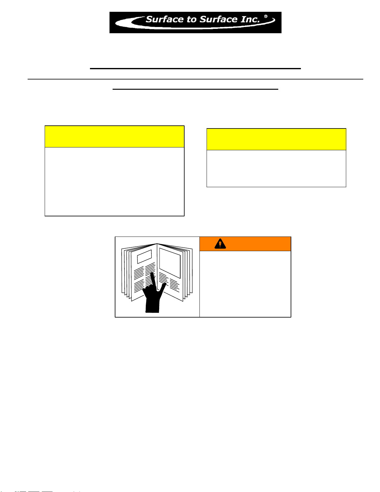
CAUTION
The manufacturer should be consulted
when considering alternative uses
for this piece of equipment.
This unit was designed for the mixing
and shearing of a dry additive, into a
liquid stream.
Other uses may create unforeseen safety
issues and personal injury risk.
CAUTION
LIFTING LUGS OR THE LIFTING POINT(S)
identified and labelled on the skid
structure must be used in order to
safely lift and transport the unit.
WARNING
REFER TO THE SAFETY
STATEMENTS IN THE
ENGINE OEM MANUAL
AND
THIS MANUAL
REGARDING THESE
OPERATIONS.

11
M2-D922
Safety Markings
Hazard and warning markings have been placed at appropriate points on the unit. International symbols
have been used, in order to ensure universal understanding of the nature of the hazard. Please comply
with all warnings and markings to ensure safe use of the equipment. These include but are not limited to:
a) Lifting points b) Flammable Liquids
c) High temperature areas d) Personal Protection recommendations
e) Personal dangers f) Equipment dangers
g) Operating instructions h) Fluid flow direction
SOME EXAMPLES THAT MAY BE FOUND ON THE EQUIPMENT
Liftin
g
Point
Personal Protection
,
Read and understand O
p
erator’s manual and Maintenance manual
Hot Surface
Fluid Flow Direction
Maintenance Instructions
Liftin
g
Point
CLEAN FILTER DAILY
Flammable Li
q
uid
12
13
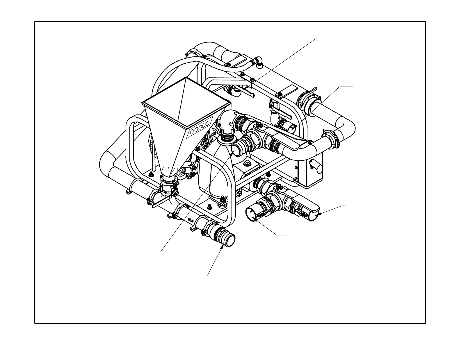
"ALL HOSES SHOULD BE KEPT TO THE SHORTEST LENGHT POSSIBLE TO ACHIEVE MAXIMUN PREFORMANCE."
FLUID OUTLET
[to Active Tank]
FLUID OUTLET
[to Mix Tank Gun "C"]
** 2" Female Cam-loc **
PUMP INTAKE
[in from Mix Tank "A"]
PUMP INTAKE
[in from Pit]
** 2" Female Cam-loc **
** 2" Male Cam-loc **
FLUID OUTLET
[to Cone Manifold "D"]
FLUID RETURN
[out to Mix Tank "B"]
** 2" Male Cam-loc **
(Hose Hook-ups)
M2-D922

14
M2-D922
Operators Manual
Congratulations on your acquisition of the world renowned M2-922 Mixing System. You have acquired
the fastest and most efficient mixing system manufactured for mixing Bentonite drilling slurry (mud). As a
manufacturer of HDD support equipment, we are well aware of the extreme conditions that HDD
equipment is exposed to on a daily basis. Surface To Surface Inc. strives to overcome these conditions,
with better design and manufacturing practices. Please feel free to call our toll free number
(1-800-567-0978) if you have any questions or concerns about your M2-922.
Thank you, for choosing the M2-922 series mixer.
The M2-922 mixing unit was designed to mix dry or liquid drilling products with clean
water, into a slurry. The slurry is continually circulated through the mixing cycle until it
reaches the desired consistency. The operator can then transfer the final product to a holding
reservoir or directly to the drilling equipment.
The M2-922 can also be combined with the STS fluid cleaning and recovery unit, to
mix drilling fluid, and to clean spent drill fluid and recover usable liquid from the solids.
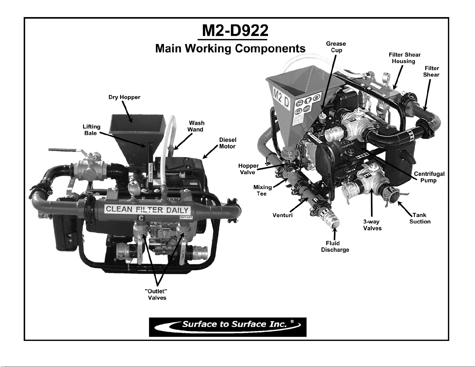
The M2-922 mixing unit consists of an diesel powered centrifugal pump, filter/shear
unit, venturi mixing tee assembly, dry hopper with a table, a set of tank internal jets
(customer installed) and a set of 3-way valves to allow quick connection / setup to the STS
fluid cleaning and recovery unit.
These components are all mounted on a frame type skid, built for lifting or solid mounting.
For ease of interpretation, looking at the mixing unit hopper straight on will be considered
looking at the front of the unit. Hence the other long side, will be the rear and the ends will be
right or left end.
RECORD OF OWNERSHIP:
• Unit Serial No. __________________________________________
• Engine Serial No.________________________________________
• Pump Serial No:_________________________________________
• Date Purchased/Leased:___________________________________
• Dealer Purchased/Leased From:_____________________________
• Special Custom Features:__________________________________
15
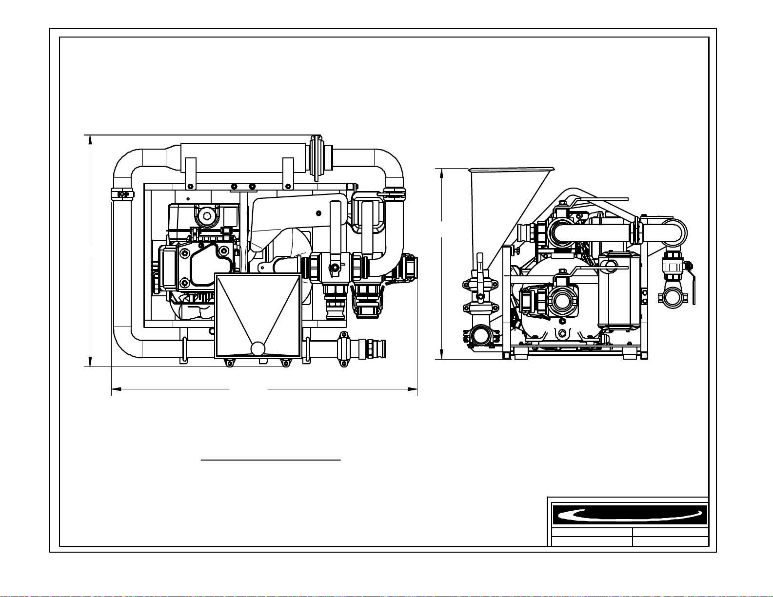
33"
REV.
DATE.DWR. NUM.
Surface to Surface Inc.
®
26 1/2"
42 1/2"
M2-D922 (Diesel)
Dry Weight: 400 Lbs (182 Kg)
M2-D922
04 / 17 / 13
* Due to our continuing productimprovement,specificationsare subject tochange without notice. *

16
Specifications M2-D922 Mixer Benefits
Dimensions 33” W x 43” L x 26 1/2” H Small space saving footprint.
Weight 400 lbs. (182 Kg) Light weight for easy transportation.
Hopper Height & Size 26 1/2” High Holds ½ of a bag Low hopper height reduces back strain.
Mixing System 2” Proprietary StS Mixing System Fast & efficient with high shearing ability.
Flow Valves Brass and Steel construction Withstand the abuse of daily operations
Skid Frame 1” steel tube with lifting bale Built tough for the construction trade.
Engine 9.0 hp air-cooled, man/ elect start Industrial rated for longer service life
Pump 2” Cast iron centrifugal trash pump Gorman-Rupp 80 series
Pump / Engine Connection Direct coupled engine & pump No expensive couplers or inserts to replace.
Pipe Couplers Bolt & Snap-groove type Fast cold weather draining of system.
Pressure Wand Hopper maintenance wand Removal of build-up caused by additive.
Internal Jet Guns (supplied) Eductor Nozzles (5-1 fluid output) Fast and effective rolling and mixing action.
Mechanical Seal Self-Pressurizing Grease Seal Greaseable seal for more rugged working conditions
Replaceable Wear Plate Hardened plate ahead of Impeller Less wear on internal pump parts and is replaceable.
3-way Valves 2 1/2” NPT Port, 2 position Designed for heavy duty slurry use. Large handles.
With a 40 second viscosity, the M2 produces 90 gpm @ 36psi through the nozzle and 52 gpm @ 36psi to the tank
internal jet guns (5-1 mixing equals 260 gpm of mixing / rolling action in tank) and a discharge rate of 80 gpm @
36psi
Features and Benefits M2-D922 Mixer
The M2-D922 universal mixer is designed around the time proven M series mixers of STS. Powered by a 9 hp air-
cooled diesel engine, driving a 2” centrifugal pump, making effective use of the proprietary 4 point mixing system. The
M2-D922 has a set of 3-way valves mounted to the suction & discharge ports of the pump that allow the operator to
choose between two different inlet sources, and a different outlet. The M2-D922 was designed for use with STS fluid
recovery systems, but may also be used as a new installation or retrofitted into an existing system of tank(s). Since the
unit is connected by hoses and not hard pipe, the placement of the mixer verses the tank(s) is less restricted and a
configuration to suit the needs of the contractor is easier to achieve. The small size also makes it a portable,
independent unit that is easier to transport from site to site.
Surface to Surface Inc.
Also available in Hydraulic (M2-H922), Electric (M2-E922) or Gasoline (M2-G922) models.
∗∗∗ All Specifications Subject to Change Without Notice ∗∗∗
Universal 2” Mixer
Model M2-D922
Surface to Surface Inc.
5150 Forest Road, R.R.#3, Watford, Ontario, N0M 2S0
Tel: 1-800-567-0978
Check our website for the latest products and specifications
www.stsmixers.com
04/18/13
33"
26 1/2"
42 1/2"
17
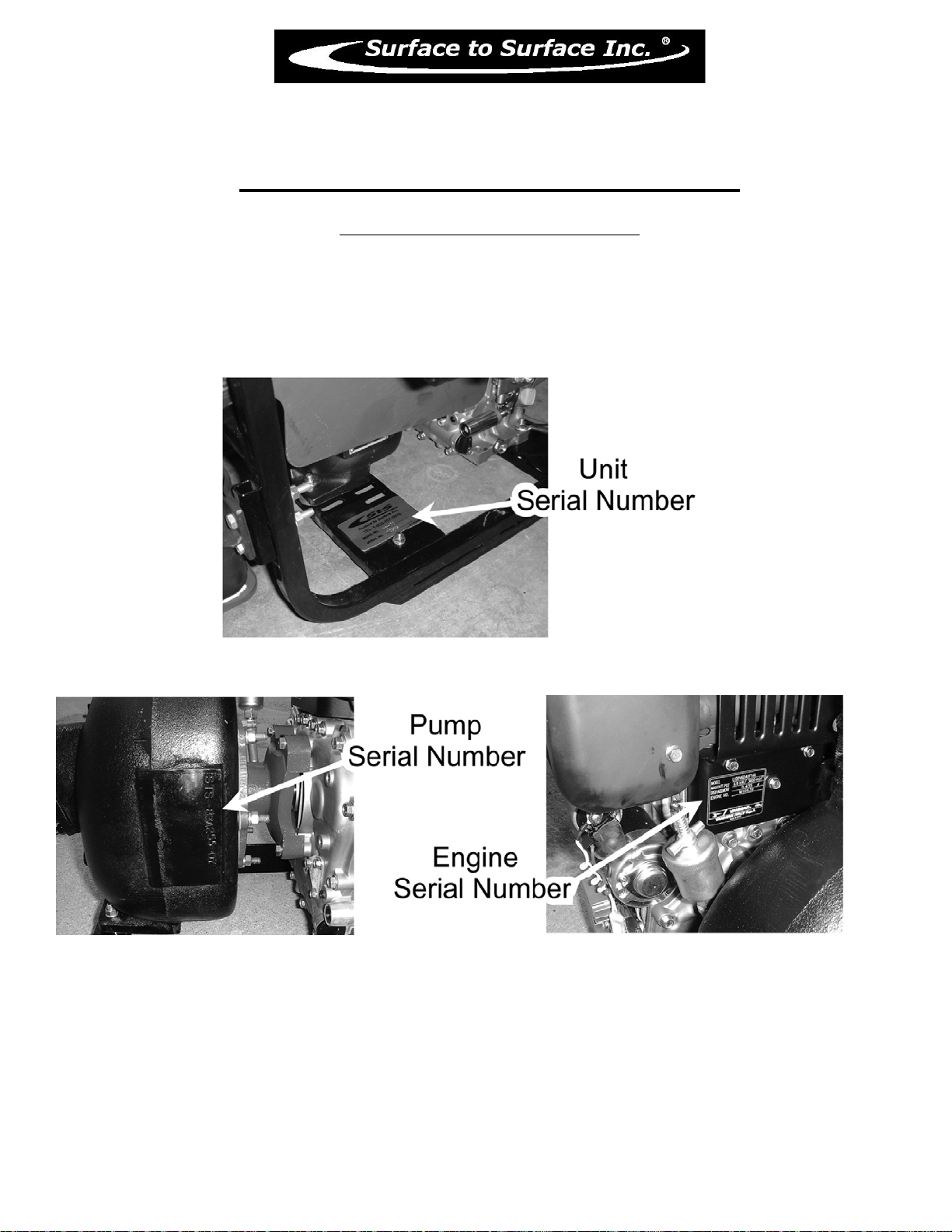
M2-D922
Identifying Your Machine & Components
Location of Tags and PIN Plates

18
SECTION #II
Description, Care and Maintenance
19
M2-D922
Description, Care and Maintenance
Diesel Powered Centrifugal Pump
Care and maintenance of the engine and pump are covered in this manual and/or the manufacturer
operator’s manuals supplied and should be read and understood. We suggest the following daily checks be
carried out prior to using the system. Check the diesel tank is full. Check oil level by removing the oil plug /
dip stick, and viewing the oil level. Check the pump seal grease cup is full (see grease cup instructions Fig.5).
Check the engine air filter (due to environmental conditions). Check that any water intake valve(s) are open
and the reservoir tank has sufficient liquid to supply the centrifugal pump.
The pump is mounted directly to the engine, so there is no “drive coupler” to check or maintain. The pump
is the primary component that will see the most wear due to the nature of the material it is handling
therefore it will require regular checks, adjustments and maintenance.
There is a section of this manual dedicated to the pump itself and should be read and understood
which will help should any problems or concerns arise in the field.
The pump should never be allowed to start or run dry, as this WILL damage the internal pump seal (grease
seal) and render the unit inoperable until the seal is fixed.
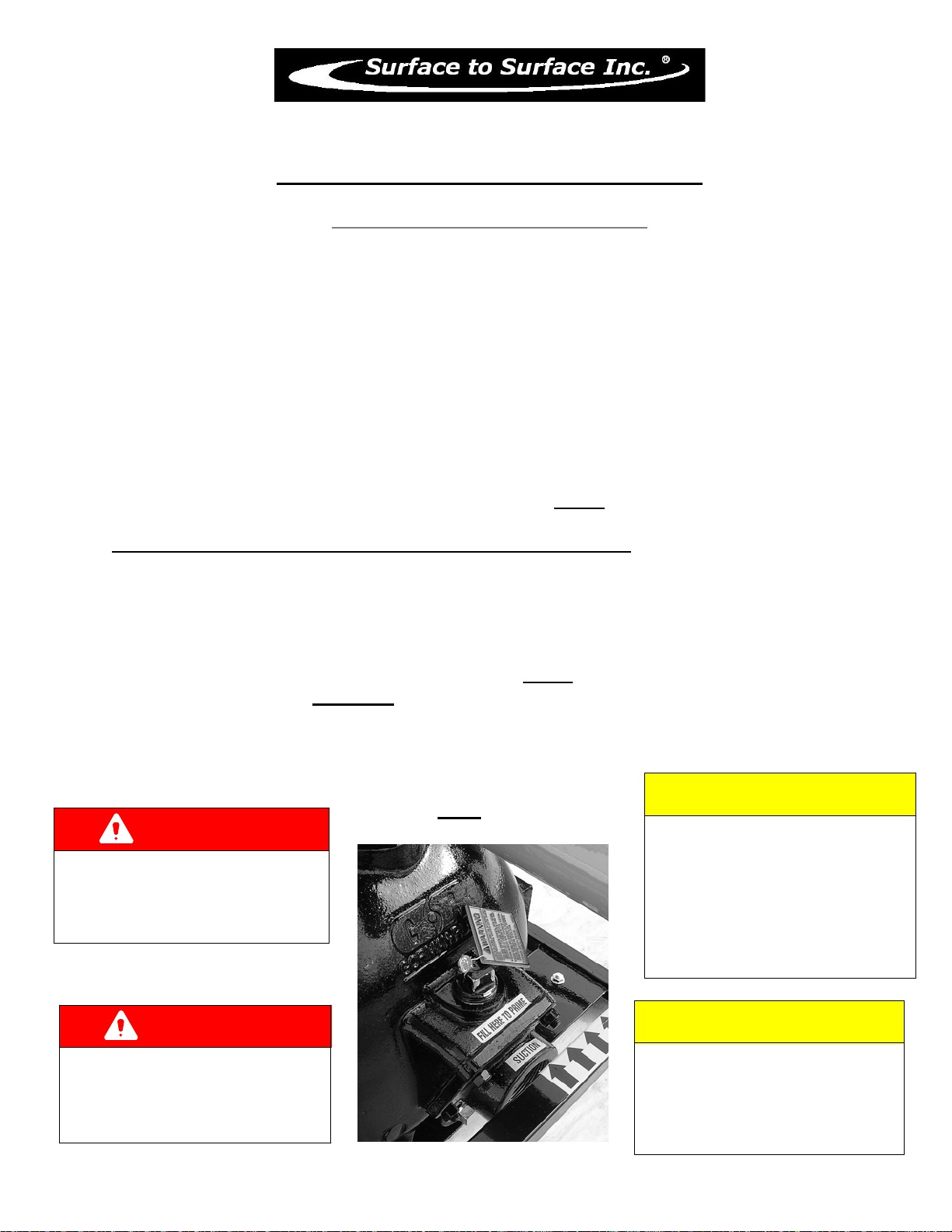
To prime the pump or check to visually see if the pump is primed, slowly undo the priming plug (see
fig. 3) on top of the pump and stop after about 3 turns. If the pump is primed, fluid & air will escape from
around the plug threads. This indicates that the pump housing is full, and the plug can be tightened back up.
If no fluid is escaping from around the threads, completely & carefully remove the plug. Drill fluid or water
can be poured into this opening to fill the pump cavity, and a visual of the fluid level inside the pump can be
made. The level should be approximately to the top of the pump priming hole.
Another way to prime the pump is to have the tank FULL of fluid, and standing off to the side of the
hopper, rotate the hopper valve SLOWLY to the open position. As the valve is opened, you will hear air
escaping followed by fluid, into the hopper itself. Close the valve as the fluid enters the hopper. This means
the fluid in the tank has filled the pump cavity of the pump and flowed from the outlet of the pump to the
remaining piping on the unit.
CAUTION
IMPROPER INSTALLATION OF THE
MECHANICAL or GREASE SEAL
will result in leakage and possible
damage to the seal. All maintenance,
operating and repair of this unit, must be
done per the instructions in the operators
manual for safety and reliability.
Fig.3 CAUTION
BEFORE STARTING THE ENGINE,
BE SURE THE PUMP IS PRIMED!
Check the pump by slowly & carefully
opening the primming plug located on
the centrifugal pump.
A visual inspection can be made if the fluid
escapes around the plug as it is loosened.
Remove the plug to view inside fluid level.
The centrifugal pump seal WILL be
damaged if allowed to cavitate or run dry.
DANGER
IN AN EMERGENCY
rotate the engine speed control lever
to the STOP position
to halt engine, pump, and fluid flow
DANGER
NEVER ATTEMPT REPAIRS
OR DISASSEMBLY
without shutting off the engine.
Serious personal injury will result.

20
M2-D922
Description, Care and Maintenance
Diesel Powered Centrifugal Pump
CAUTION
NEVER LEAVE LIQUID IN THE
PUMP CASING, PIPING, OR HOSES
during freezing weather conditions,
as damage will result.
Follow instruction for winterizing.
CAUTION
TRAPPED FLUID MAY BE PRESENT
and will spill out when piping, hoses,
pump or filter shear are removed.
Fig.4
WARNING
REFER TO THE SAFETY
STATEMENTS IN THE
OEM SUPPLIED MANUALS
AND
THIS MANUAL
REGARDING THESE
OPERATIONS.
CAUTION
BEFORE STARTING OR RESTARTING
the engine and centrifugal pump, make
sure any valves installed on the pump
suction inlet line are open, and the
fluid level in the tank is above
the suction line.
Table of contents
Other STS Industrial Equipment manuals


Popular Industrial Equipment manuals by other brands

ASTEC
ASTEC 40 Series Operation and maintenance manual

Hydrotech
Hydrotech HSF2200 Series Operation & maintenance manual

Balluff
Balluff BTL PA0400 Series user guide

PCM
PCM VDF-401 operating instructions

ABB
ABB HT610894 Operation manual

Enoitalia
Enoitalia Bag in Box BB 50 Instructions for use and installation


