Huber HTS Series User manual

HTS®
Heat Transfer
Station


OPERATION MANUAL
HTS®
Heat Transfer
Station


OPERATION MANUAL
V2.4.0en/22.02.22//17.12 Heat Transfer Station
5
Heat Transfer Station
Pilot ONE®
This operation manual is a translation of the original operation manual.
Also for models with heater.
VALID FOR:
HTS 3
HTS 5
HTS 6
HTS 15
HTS 30
HTS 50
HTS 75
Abbreviations in model designation:
-H = heater

OPERATION MANUAL
Heat Transfer Station V2.4.0en/22.02.22//17.12
6
„Pilot ONE“
Layout of the “Home”
screen

OPERATION MANUAL
V2.4.0en/22.02.22//17.12 Heat Transfer Station
7
Table of contents
V2.4.0en/22.02.22//17.12
1Introduction 12
1.1 Identification / symbols in the operation manual ......................................... 12
1.2 Information on the EU Declaration of Conformity......................................... 12
1.3 Safety .......................................................................................................... 12
1.3.1 Symbols used for Safety Instructions..............................................................12
1.3.2 Representation of safety identifiers on the temperature control unit...........13
1.3.3 Proper operation.............................................................................................13
1.3.4 Reasonably foreseeable misuse......................................................................14
1.4 Responsible bodies and operators – Obligations and requirements ..................... 15
1.4.1 Obligations of the responsible body ...............................................................15
1.4.1.1 Proper disposal of resources and consumables .........................................15
1.4.2 Requirements for operators ...........................................................................15
1.4.3 Obligations of the operators...........................................................................16
1.5 General information..................................................................................... 16
1.5.1 Description of workstation .............................................................................16
1.5.2 Safety devices to DIN 12876 ...........................................................................16
1.5.3 Further protective devices ..............................................................................17
1.5.3.1 Power interruption.....................................................................................17
1.5.3.2 Alarm functions ..........................................................................................18
1.5.3.3 Warning messages......................................................................................18
1.6 Exemplary illustrations of the cooling variants.............................................. 18
1.6.1 Consequence of inadequate energy dissipation.............................................19
2Commissioning 20
2.1 In-plant transport......................................................................................... 20
2.1.1 Lifting and transporting the temperature control unit...................................20
2.1.1.1 Temperature control unit with lifting eyes ................................................20
2.1.1.2 Temperature control unit without lifting eyes...........................................21
2.1.2 Mounting/removing leveling feet...................................................................21
2.1.3 Positioning the temperature control unit.......................................................22
2.1.3.1 Temperature control unit with casters ......................................................22
2.1.3.2 Temperature control unit without casters.................................................22
2.2 Unpacking.................................................................................................... 22
2.3 Ambient conditions...................................................................................... 22
2.3.1 EMC-specific notes..........................................................................................24
2.4 Installation conditions.................................................................................. 24
2.5 Recommended temperature control and cooling water hoses ...................... 25
2.6 Wrench sizes and torques............................................................................. 26
2.7 Temperature control units with water cooling.............................................. 26
2.8 Preparations for operation ........................................................................... 28
2.8.1 Opening/closing valves ...................................................................................28
2.8.2Installing collecting container .........................................................................28
2.8.3 Connecting the functional earth.....................................................................28
2.9 Connecting externally closed application...................................................... 28
2.9.1 Connecting an externally closed application ..................................................28
2.10 Connecting to the power supply ................................................................... 29
2.10.1 Connection using socket with protective earth (PE).......................................29

OPERATION MANUAL
Heat Transfer Station V2.4.0en/22.02.22//17.12
8
2.10.2 Connection via hard wiring .............................................................................29
3Function description 31
3.1 Function description of the temperature control unit ................................... 31
3.1.1 General functions............................................................................................31
3.1.2 Other functions...............................................................................................31
3.2 Information on the thermal fluids ................................................................ 31
3.3 To be noted when planning the test ............................................................. 32
3.4 “Pilot ONE®” controller ................................................................................ 33
3.4.1 Functional overview of “Pilot ONE®” ..............................................................33
3.5 Clock/event function.................................................................................... 35
3.5.1 Rechargeable accumulator .............................................................................35
3.5.2 Programmable event function ........................................................................36
3.5.2.1 Event function “Alarm clock event” ...........................................................36
3.5.2.2 Event function “Program event” ................................................................36
3.6 Operation via the touch screen..................................................................... 36
3.7 Display instruments ..................................................................................... 36
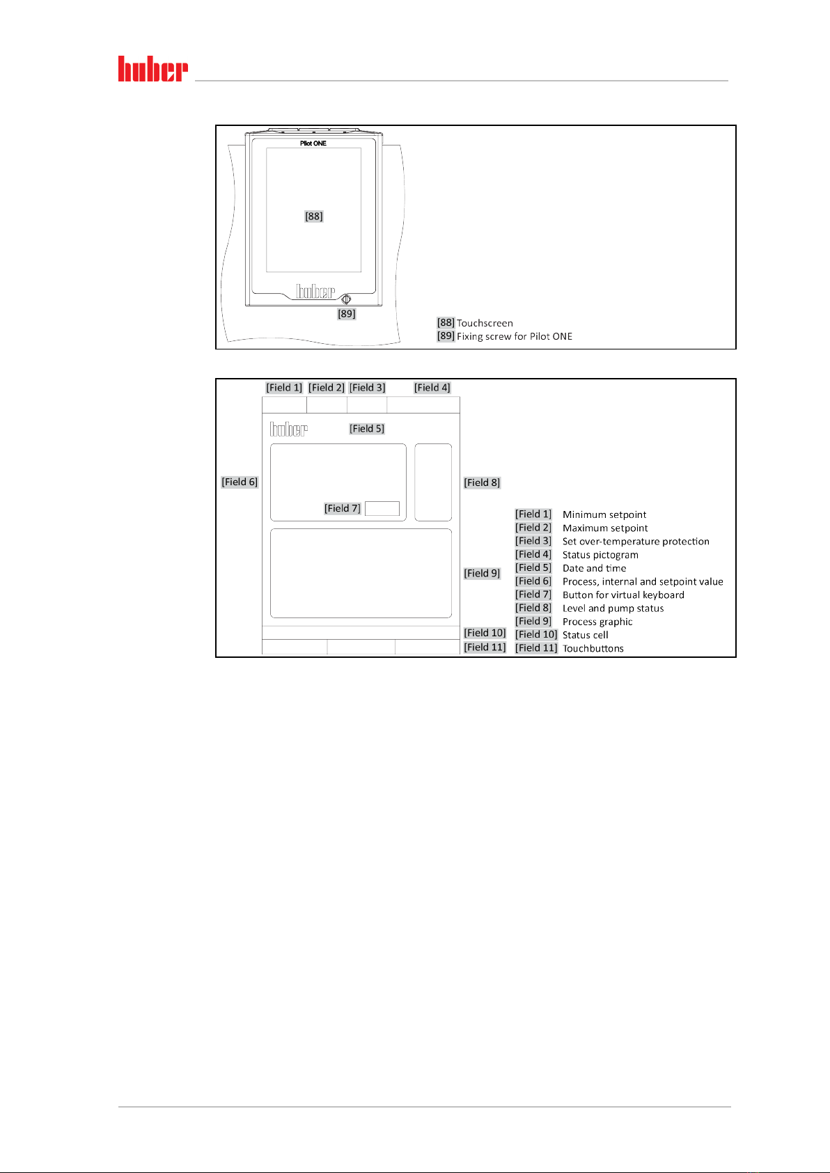
3.7.1 The touchscreen [88] ......................................................................................37
3.8 Control instruments ..................................................................................... 37
3.8.1 The touchbuttons............................................................................................37
3.8.2 The categories.................................................................................................37
3.8.3 The sub-categories..........................................................................................37
3.8.4 The dialogs ......................................................................................................37
3.9 Function examples ....................................................................................... 38
3.9.1 Display of software version.............................................................................38
3.9.2 Start & Stop.....................................................................................................38
3.9.3 Copying the settings to a data carrier.............................................................39
3.9.3.1 Saving to a USB flash drive .........................................................................39
3.9.3.2 Loading from a USB flash drive...................................................................39
3.9.4 Restore factory settings ..................................................................................39
3.9.4.1 Restore to factory settings without overtemperature protection .............41
3.9.4.2 Restore to factory settings including overtemperature protection ...........41
4Setup mode 42
4.1 Setup mode ................................................................................................. 42
4.1.1 Turning on the temperature control unit .......................................................42
4.1.2 Turning off the temperature control unit.......................................................42
4.1.3 Setting the overtemperature protection ........................................................43
4.1.3.1 General information on the overtemperature protection .........................43
4.1.3.2 Setting “OT limit: heating” .........................................................................43
4.1.3.3 Setting “OT expansion vessel”....................................................................44
4.1.3.4 Setting “Process Safety” .............................................................................44
4.1.3.5 Monitoring via “Display OT values”............................................................44
4.1.4 Testing overtemperature protection for functionality ...................................45
4.1.5 Adjusting the Delta T limiter ...........................................................................45
4.1.5.1 Changing the Delta T limiter.......................................................................45
4.2 The temperature control circuit.................................................................... 45
4.2.1 Select temperature control: Internal or process ............................................46
4.2.2 Temperature control to internal temperature ...............................................46
4.2.3 Temperature control to process temperature................................................47
4.2.4 Delta T limiter .................................................................................................47
4.2.5 Monitoring the Pt100 temperature sensors...................................................47
4.2.6 Optimum control parameters for optimum temperature control..................48

OPERATION MANUAL
V2.4.0en/22.02.22//17.12 Heat Transfer Station
9
4.2.7 Sub-category: “Select auto/expert mode”......................................................48
4.2.8 Sub-category: “Configuration auto” ...............................................................48
4.2.8.1 Sub-category: “Find parameters”...............................................................48
4.2.8.2 Sub-category: “Control Dynamics”.............................................................50
4.2.8.3 Sub-category: “Fluid Properties”................................................................51
4.2.8.4 Sub-category: “Display parameters” ..........................................................52
4.2.9 Sub-category: “Configuration manual”...........................................................53
4.2.9.1 Sub-category: “Change parameters”..........................................................53
4.2.9.2 Sub-category: “Display parameters” ..........................................................54
4.2.9.3 Sub-category: “Control structure”..............................................................54
4.2.10 Sub-category: “Reset parameters” .................................................................54
4.2.11 Sub-category: “Display parameters”...............................................................55
4.2.12 Setting the setpoint thresholds ......................................................................55
4.2.13 Setting the setpoint ........................................................................................56
4.3 Filling, venting, degassing and draining......................................................... 56
4.3.1 Externally closed application ..........................................................................56
4.3.1.1 Filling and venting externally closed application........................................56
4.3.1.2 Degassing externally closed applications ...................................................58
4.3.1.3 Draining externally closed applications......................................................60
5Normal operation 63
5.1 Automatic operation .................................................................................... 63
5.1.1 Temperature control.......................................................................................63
5.1.1.1 Starting the temperature control process..................................................63
5.1.1.2 Ending the temperature control process ...................................................63
5.1.2 Temperature control via a created temperature control program ................64
5.1.2.1 Starting the temperature control program ................................................64
5.1.2.2 Ending/cancelling the temperature control program ................................64
6Interfaces and software update 65
6.1 Interfaces at the “Pilot ONE®” controller ...................................................... 65
6.1.1 10/100 Mbps Ethernet for RJ45 network sockets ..........................................65
6.1.2 USB-2.0 interface ............................................................................................65
6.1.2.1 USB-2.0 interface, host...............................................................................66
6.1.2.2 USB-2.0 interface, device ...........................................................................66
6.2 Interfaces on the temperature control unit................................................... 66
6.2.1 Interfaces at the top .......................................................................................66
6.2.1.1Connection jack for Pt100 process controller sensor.................................66
6.2.2 Interfaces at the back .....................................................................................67
6.2.2.1 Connector POKO (floating contact) alarm..................................................67
6.2.2.2 Female RS232 serial....................................................................................68
6.2.2.3Service interface.........................................................................................69
6.3 Interfaces at the Com.G@te® (optional) ....................................................... 69
6.3.1 Jack LEVEL (Com.G@te® external only) ..........................................................69
6.3.2 Connector POKO (floating contact) alarm ......................................................70
6.3.3 Jack AIF Reg-E-Prog.........................................................................................70
6.3.4 Jack ECS (External Control Signal) standby .....................................................70
6.3.5 Jack RS232/RS485 serial..................................................................................71
6.4 Firmware update.......................................................................................... 71
7Service/maintenance 72
7.1 Messages from the temperature control unit ............................................... 72
7.2 Electrical fuse............................................................................................... 72

OPERATION MANUAL
Heat Transfer Station V2.4.0en/22.02.22//17.12
10
7.3 Replacing the “Pilot ONE®”........................................................................... 72
7.4 Maintenance................................................................................................ 73
7.4.1 Function check and visual inspection .............................................................73
7.4.2 Replacing temperature control or coolant hoses ...........................................74
7.4.2.1 Replacing temperature control hoses ........................................................74
7.4.2.2 Replacing coolant hoses .............................................................................74
7.4.3 Clean hat-type strainer (dirt trap) (water-cooled temperature control unit).74
7.5 Thermal fluid inspection, replacement and circuit cleaning........................... 75
7.5.1 Thermal fluid inspection .................................................................................75
7.5.2 Thermal fluid replacement .............................................................................76
7.5.2.1 Externally closed application......................................................................76
7.5.3 Rinsing the thermal fluid circuit......................................................................76
7.6 Cleaning the surfaces ................................................................................... 78
7.7 Inspect the mechanical seal.......................................................................... 78
7.8Plug contacts................................................................................................ 78
7.9 Decontamination/repairs ............................................................................. 78
8Shutting down 80
8.1 Safety instructions and basic principles ........................................................ 80
8.2 Switch-off .................................................................................................... 81
8.3 Draining the temperature control unit.......................................................... 81
8.4 Draining the cooling water ........................................................................... 81
8.4.1 Draining process .............................................................................................81
8.5 Deinstalling the collecting container............................................................. 82
8.6 Uninstalling an external application ............................................................. 82
8.7 Packing ........................................................................................................ 82
8.8 Shipping....................................................................................................... 82
8.9 Disposal ....................................................................................................... 83
8.10 Contact data ................................................................................................ 83
8.10.1 Telephone number: Customer Support ..........................................................83
8.10.2 Telephone number: Sales ...............................................................................83
8.10.3 Email address: Customer Support...................................................................83
8.11 Certificate of Compliance ............................................................................. 83
9Annex 84

OPERATION MANUAL
V2.4.0en/22.02.22//17.12 Heat Transfer Station
11
Foreword
Dear Customer,
Thank you for choosing a temperature control unit from Peter Huber Kältemaschinenbau SE. You
have made a good choice. Thank you for your trust.
Please read the operation manual carefully before putting the unit into operation. Strictly follow all
notes and safety instructions.
Follow the operation manual with regard to transport, start-up, operation, maintenance, repair,
storage and disposal of the temperature control unit.
We fully warrant the temperature control unit for the specified intended operation.
The models listed on page 5 are referred to in this operation manual as temperature control units
and Peter Huber Kältemaschinenbau SE as Huber company or Huber.
Liability for errors and misprints excluded.
The following trademarks and the Huber logo are registered trademarks of Peter Huber Kältemaschinenbau SE in
Germany and/or other countries worldwide: BFT®, CC®, Chili®, Com.G@te®, Compatible Control®, CoolNet®,
DC®, E-grade®, Grande Fleur®, Huber Piccolo®, KISS®, Minichiller®, Ministat®, MP®, MPC®, Peter Huber Mini-
chiller®, Petite Fleur®, Pilot ONE®, RotaCool®, Rotostat®, SpyControl®, SpyLight®, Tango®, TC®, UC®, Unical®,
Unichiller®, Unimotive®, Unipump®, Unistat®, Unistat Tango®, Variostat®. The following trademarks are regis-
tered in Germany to DWS Synthesetechnik: DW-Therm®, DW-Therm HT®. The following trademark is a registered
trademark of BASF SE: Glysantin®.

Introduction
OPERATION MANUAL Chapter 1
Heat Transfer Station V2.4.0en/22.02.22//17.12
12
1Introduction
1.1 Identification / symbols in the operation manual
The following identifications and symbols are used in the texts and illustrations.
Identification / symbol Description
→Reference to information / procedure.
»TEXT« Reference to a chapter in the operation manual. In the digital version, the text
is clickable.
>TEXT< [NUMBER] Reference to the wiring diagram in the annex. The designation and the search
digit are specified.
>TEXT< [LETTER] Reference to a drawing in the same paragraph. The designation and the
search digit are specified.
▪List, first level
‒List, second level
1.2 Information on the EU Declaration of Conformity
The equipment complies with the basic health and safety requirements of the European Directives
listed below:
▪Machinery Directive
▪Low Voltage Directive
▪EMC Directive
1.3 Safety
1.3.1 Symbols used for Safety Instructions
Safety instructions are marked by the below combinations of pictograms and signal words. The
signal word describes the classification of the residual risk when disregarding the operation manual.
Denotes an immediate hazardous situation that will result in death or serious injuries.
Denotes a general hazardous situation that may result in death or serious injuries.
Denotes a hazardous situation that can result in injury.
Denotes a situation that can result in property material damage.
Denotes important notes and usable hints.
Overview

Introduction
Chapter 1 OPERATION MANUAL
V2.4.0en/22.02.22//17.12 Heat Transfer Station
13
Notes in conjunction with Ex px cabinets.
The safety information in this operation manual is designed to protect the operating company, the
operator and the equipment from damage. First inform yourself about any residual risks due to
misuse before you start an operation.
1.3.2 Representation of safety identifiers on the temperature control unit
The following pictograms are used as safety identifiers. The table gives an overview of the safety
identifiers used here.
Identifier Description
Mandatory sign
- Observe the instructions
Warning sign
- General warning sign
- Observe the instructions
- Warning of electrical voltage
- Warning of hot surface
- Warning of flammable substances
1.3.3 Proper operation
Operating the temperature control unit in a potentially explosive area
DEATH THROUGH EXPLOSION
Do NOT install or start up the temperature control unit within an ATEX zone.
Safety information and
procedure
Overview

Introduction
OPERATION MANUAL Chapter 1
Heat Transfer Station V2.4.0en/22.02.22//17.12
14
Improper use
SERIOUS INJURY AND PROPERTY DAMAGE
Store the operation manual where it is easy to access in close proximity to the temperature
control unit.
Only adequately qualified operators may work with the temperature control unit.
Operators must be trained before handling the temperature control unit.
Check that the operators have read and understood the operation manual.
Define precise responsibilities of the operators.
Personal protective equipment must be provided to the operators.
Be sure to follow the responsible body’s safety rules to protect life and limb and to limit dam-
ages!
Modifications to the temperature control unit by third-parties
DAMAGE TO THE TEMPERATURE CONTROL UNIT
Do not allow third parties to make technical modifications to the temperature control unit.
The EU declaration of conformity becomes invalid if any modifications are made to the tem-
perature control unit without the approval of Huber.
Only specialists trained by Huber may carry out modifications, repairs or maintenance work.
The following must be observed without fail:
Only use the temperature control unit in a fault-free condition!
Have the start-up and repairs carried out by specialists only!
Do not ignore, bypass, dismantle or disconnect any safety devices!
The temperature control unit must not be used for any purposes other than temperature control in
accordance with the operation manual.
The temperature control unit is made for industrial use. The temperature control unit is used to
maintain the temperature of applications, such as glass or metal reactors or other expedient items
in laboratories and industry. Flow-through coolers and calibration baths must be used only in com-
bination with Huber temperature control units. Only use thermal fluids suitable for the overall sys-
tem. The cooling or heating capacity is provided at the pump connections or - where present - in the
tempering bath. For the technical specification, refer to the datasheet. →From page 84, section
»Annex«. Install, set up and operate the temperature control unit according to the instructions in
this operation manual. Any failure to comply with the operation manual is considered as improper
operation. The temperature control unit was manufactured according to the state of the art and the
recognized safety rules and regulations. Safety devices are installed in your temperature control
unit.
1.3.4 Reasonably foreseeable misuse
Without an Ex px cabinet, the temperature control unit / accessory is NOT protected against ex-
plosion and must NOT be installed or put into operation within an ATEX Zone. When operating the
temperature control unit /accessory in conjunction with an Ex px cabinet, the information in the
annex (Section ATEX operation) must be observed and followed. This annex is only provided for
temperature control units /accessories delivered with an Ex px cabinet. If this annex is missing,
please immediately contact the Customer Support. →Page 83, section »Contact data«.
Use with medical devices (e.g. in Vitro diagnostic procedure) or for direct foodstuff temperature
control is NOT permissible.
The temperature control unit must NOT be used for any purposes other than temperature control in
accordance with the operation manual.
The manufacturer accepts NO liability for damage caused by technical modifications to the temper-
ature control unit, improper handling or use of the temperature control unit if the operation manu-
al is not observed.

Introduction
Chapter 1 OPERATION MANUAL
V2.4.0en/22.02.22//17.12 Heat Transfer Station
15
1.4 Responsible bodies and operators – Obligations and requirements
1.4.1 Obligations of the responsible body
The operation manual is to be stored where it is easy to access in close proximity to the temperature
control unit. Only adequately qualified operators (e.g. chemists, CTA, physicists etc.) are permitted to
work with the temperature control unit. Operators must be trained before handling the temperature
control unit. Check that the operators have read and understood the operation manual. Define precise
responsibilities of the operators. Personal protective equipment must be provided to the operators.
▪The responsible body must install a condensation water / thermal fluid drip tray below the tem-
perature control unit.
▪The use of a drip tray may be prescribed by national legislation for the installation area of the
temperature control unit (incl. accessory). The responsible body must check and apply the na-
tional regulations applicable for it accordingly.
▪The temperature control unit complies with all applicable safety standards.
▪Your system, which uses our temperature control unit, must be equally safe.
▪The responsible body must design the system to ensure it is safe.
▪Huber is not responsible for the safety of your system. The responsible body is responsible for the
safety of the system.
▪Although the temperature control unit provided by Huber meets all the applicable safety stand-
ards, integration into a system may give rise to hazards that are characteristic of the other sys-
tem’s design and beyond the control of Huber.
▪It is the responsibility of the system integrator to ensure that the overall system, into which this
temperature control unit is integrated, is safe.
▪The >Mains isolator< [36] (if present) can be locked in the off position to facilitate safe system
installation and maintenance of the temperature control unit. It is the responsibility of the re-
sponsible body to develop any lock-out/tag-out procedure for the energy source in accordance
with local regulations (e.g. CFR 1910.147 for the US).
1.4.1.1 Proper disposal of resources and consumables
Do comply with all national disposal regulations applicable for you. Contact your local waste man-
agement company for any questions concerning disposal.
Material / Aids Disposal / Cleaning
Packaging material Keep the packaging material for future use (e.g. transport).
Thermal fluid
Please refer to the safety data sheet of the thermal fluid used for information on its
proper disposal.
Use the original thermal fluid container when disposing it.
Filling accessories, e.g.
beaker
Clean the filling accessories for reuse. Make sure that the materials and cleaning
agents used are properly disposed of.
Aids such as towels,
cleaning cloths
Tools used to take up spilled thermal fluid must be disposed of in the same fashion
as the thermal fluid itself.
Tools used for cleaning must be disposed of depending on the cleaning agent used.
Cleaning agents such as
stainless steel cleaning
agents, sensitive-fabrics
detergents
Please refer to the safety data sheet of the cleaning agent used for information on its
proper disposal.
Use the original containers when disposing of large quantities of cleaning agents.
Consumables such as air
filter mats, temperature
control hoses
Please refer to the safety data sheet of the consumables used for information on
their proper disposal.
1.4.2 Requirements for operators
Work on the temperature control unit is reserved for appropriately qualified specialists, who have
been assigned and trained by the responsible body to do so. Operators must be at least 18 years old.
Under 18-year olds may operate the temperature control unit only under the supervision of a quali-
fied specialist. The operator is responsible vis-a-vis third-parties in the work area.
Overview

Introduction
OPERATION MANUAL Chapter 1
Heat Transfer Station V2.4.0en/22.02.22//17.12
16
1.4.3 Obligations of the operators
Carefully read the operation manual before operating the temperature control unit. Please observe
the safety instructions. When operating the temperature control unit, wear appropriate personal
protective equipment (e.g. safety goggles, protective gloves, non-slip shoes).
1.5 General information
1.5.1 Description of workstation
The workstation is located at the control panel in front of the temperature control unit. The workstation is
determined by the customer's connected peripheries. Accordingly, it must be designed safe by the re-
sponsible body. The workstation design also depends on the applicable requirements of the German
occupational health and safety regulations [BetrSichV] and the risk analysis for the workstation.
1.5.2 Safety devices to DIN 12876
The rating of your temperature control unit is stated on the data sheet in the appendix.
Classification Temperature
control medium Technical requirements Identification d)
I Non-combustible a) Overheat protection c) NFL
II Combustible b) Adjustable overheat protection FL
III Combustible b) Adjustable overtemperature protection
and additional low-level protection FL
a) Usually water; other fluids only if non-combustible even within the temperature range of an individual fault.
b) The temperature control media must have a fire point of ≥ 65 °C.
c) The overheat protection can, for instance, be realized using a suitable fill level sensor or a suitable temperature limiter.
d) Optional at the choice of the manufacturer.
Combined electronic low level and overtemperature protection
This temperature control unit has been equipped with an electronic overtemperature protection
and low-level protection. Instead of a mechanical float switch, temperature sensors are employed
on the surface of the heating coils. These sensors monitor overtemperature at this potential ignition
source, thus ensuring the controller regulates the heating coil temperatures below the critical tem-
perature (fire point of the thermal fluid). An appropriate message is output via the >Touchscreen<
[88].
There is no longer a need for mechanical tools to set the trigger values of the overtemperature
protection. It is replaced by a software engineering tool. The threshold value for the overtempera-
ture protection can be set only if a code, randomly generated by “Pilot ONE”, is entered correctly. As
with the mechanical tool, accidental settings are thus prevented.
Rating of laboratory
thermostats and
laboratory baths
Overview of the tem-
perature thresholds

Introduction
Chapter 1 OPERATION MANUAL
V2.4.0en/22.02.22//17.12 Heat Transfer Station
17
Low level protection
Low level protection is achieved via a pressure sensor in the fluid circuit. The pump ensures, togeth-
er with the thermal fluid, the requisite pressure at the pressure sensor. Air in the system (fill level
too low, inadequately vented) prevents the pressure from reaching value specified at the pressure
sensor. Temperature control and circulation are interrupted.
Overtemperature protection (for temperature control units with heating)
Mechanical tools are no longer required for setting the trip values for the overtemperature protec-
tion. A software tool is used instead. The threshold value for the overtemperature protection can be
set only if a code randomly generated by “Pilot ONE” beforehand is entered correctly. As with the
mechanical tool, accidental settings are thus prevented. The type of overtemperature protection
function and of low level protection depends on the temperature control unit.
Process safety
This type of overtemperature operating mode is driven by a desire for further protection of operator
and system. Protective devices typically disconnect all poles when reaching the overtemperature
protection trigger value. This may result in more heat being fed into the process (e.g. exothermic
reaction) than the existing cooling machine is able to cool as the overtemperature protection trigger
value is usually set above the controller setpoint. Turning off the temperature control unit elimi-
nates the only possibility to extract heat from the process. The temperature could therefore rise
further and system components could be heated up above their rated temperatures, which could
e.g. cause danger to life and limb by rupture of the material or phase transitions from liquid to gase-
ous state. In Process Safety mode, the controller recognizes when the trigger value at the over-
temperature protection is reached, and then enables the cooling system. Even if the temperature
continues to rise, the cooling machine will use its maximum cooling capacity to keep any further
increase in temperature as low as possible. Strictly note the following: →From page 43, section
»Setting the overtemperature protection«.
1.5.3 Further protective devices
Emergency strategy – interrupt the power grid connection!
To determine the type of switch or switch combination your temperature control unit is equipped
with, please refer to the wiring diagram. →From page 84, section »Annex«.
Temperature control units with >Mains isolator< [36] (red/yellow or gray): Turn the >Mains
isolator< [36] to the “0” position.
Temperature control units with >Mains isolator< [36] (red/yellow) and additional >Appliance
switch< [37] (gray): Turn the >Mains isolator< [36] to the “0” position. Then turn the >Appliance
switch< [37] to the “0” position!
Temperature control units with >Mains isolator< [36] (gray) and >Emergency stop switch< [70]
(red/yellow): Press the >Emergency stop switch< [70]. Then turn the >Main switch< [36] to the
“0” position!
Temperature control units with >Mains switch< [37]:Power supply via socket: Disconnect the
temperature control unit from the power supply. Then turn the >Mains isolator< [37] to the “0”
position! Power supply via hard wiring: Disconnect the power grid supply by means of the build-
ing’s circuit breaker. Then turn the >Mains isolator< [37] to the “0” position!
Temperature control units without a switch or inside a protective housing: Connection via sock-
et: Disconnect the temperature control unit from the power supply. Connection via hard wiring:
Disconnect the power grid supply by means of the building’s circuit breaker!
1.5.3.1 Power interruption
Following a power outage (or when switching on the temperature control unit), this function can be
used to determine how the temperature control unit is supposed to respond. This response can be
determined via “Pilot ONE”.
OFF/Standby (Default setting)
After turning the temperature control unit on, thermoregulation is started only after manual input.
ON / Temperature control active
After turning on the temperature control unit, thermoregulation is always started. An INFO appears
for a few seconds. This makes it possible to suppress the automatic start.

Introduction
OPERATION MANUAL Chapter 1
Heat Transfer Station V2.4.0en/22.02.22//17.12
18
Power Failure Auto
If temperature control is active during a power outage, the process will automatically continue after
the power outage.
1.5.3.2 Alarm functions
An alarm is a system state that signals unfavorable process conditions. The temperature control unit
can be programmed so that the plant operator is warned when defined limit values are exceeded.
The response of the temperature control unit to an alarm can be determined. Possible responses
are: Switch off temperature control or control temperature to a safe setpoint (2nd setpoint).
1.5.3.3 Warning messages
Warning messages contain a message about the irregularity of the temperature control unit. These
messages have no further consequences. The plant operator evaluates the relevance of the message
and takes action where necessary.
1.6 Exemplary illustrations of the cooling variants
Example: Air and
water cooling
Air cooling: Air inlet

Introduction
Chapter 1 OPERATION MANUAL
V2.4.0en/22.02.22//17.12 Heat Transfer Station
19
1.6.1 Consequence of inadequate energy dissipation
Room air/cooling water
Consequences of, for instance, contamination of the liquefier fins, inadequate clearance between
temperature control unit to wall/bath wall, room air/cooling water too warm, cooling water differ-
ential pressure too low, suction strainer contamination: The refrigerant in the coolant circuit can no
longer fully discharge the admitted energy to the room air/cooling water. Thus there is not sufficient
liquefied refrigerant available, the condensation temperature and the energy consumption to rise.
Coolant circuit
Consequences of inadequate refrigerant quantity/rising condensation temperature: Not all the
cooling capacity from the coolant circuit is available at the evaporator. This means reduced energy
transmission from the thermal fluid circuit.
Thermal fluid circuit
Consequence of inadequate energy dissipation from the thermal fluid: The thermal fluid can only
dissipate the energy from your application to a limited extent.
Application
Consequences of inadequate energy dissipation from the application: The energy created (exother-
mic) in the application can no longer be fully dissipated.
Temperature control unit
An electronically-controlled expansion valve is used in the temperature control unit to optimize the
power adjustment. The expansion valve always provisions the maximum possible cooling capacity
within the permissible ambient temperature range. The temperature control unit switches off when
the upper range is reached (maximum permissible ambient temperature).
Water cooling: Water
connection

Commissioning
OPERATION MANUAL Chapter 2
Heat Transfer Station V2.4.0en/22.02.22//17.12
20
2Commissioning
2.1 In-plant transport
Temperature control unit transported in a horizontal position
DAMAGE TO THE COMPRESSOR
Only transport the temperature control unit in an upright position.
Filled temperature control unit is transported
MATERIAL DAMAGE DUE TO OVERFLOWING THERMAL FLUID
Only transport an emptied temperature control unit.
▪If available, use the lugs on the top side of the temperature control unit for transportation.
▪Use an industrial truck for transport.
▪Remove the packing material (e.g. the palette) only at the place of installation.
▪Protect the temperature control unit from transport damage.
▪Do not transport the temperature control unit alone and without aids.
▪Check the load bearing capacity of the transportation route and the place of installation.
2.1.1 Lifting and transporting the temperature control unit
2.1.1.1 Temperature control unit with lifting eyes
The temperature control unit is raised at the lifting eyes without load handling attachments
DAMAGE TO THE TEMPERATURE CONTROL UNIT
Always use load handling attachments when lifting and transporting the temperature control unit.
The lifting eyes are only designed for a load without inclination (0°).
The load handling attachment used must be adequately dimensioned. Take the dimensions and
weight of the temperature control unit into account.
▪Do not lift and transport the temperature control unit at the lifting eyes alone and without aids.
▪Lift and transport the temperature control unit at the lifting eyes only with a crane or an industrial truck.
▪The crane or industrial truck must have a lifting force equal to or greater than the weight of the
temperature control unit. See the data sheet for the weight of the temperature control unit.
→From page 84, section »Annex«.
▪If the leveling feet have been removed for shipping: Only lower the temperature control unit when all
leveling feet have been installed. →Page 21, section »Mounting/removing leveling feet«.
Example: lifting eyes
(round, angular, and
recessed (left to right))
This manual suits for next models
7
Table of contents
Other Huber Industrial Equipment manuals
Popular Industrial Equipment manuals by other brands

Halma
Halma Ampac EV3000 Installation & commissioning

LEGRAND
LEGRAND 0 035 46 instruction manual

Team
Team SILK SX28-72 instruction manual

GRUNDFOS ALLDOS
GRUNDFOS ALLDOS Oxiperm C 164 Series Operation and service manual

Eaton
Eaton DILM XSP/E(RDC48) Series Instruction leaflet

MicroStep
MicroStep Start Shaphon SH-HC31 manual

Spirax Sarco
Spirax Sarco UFT32 Installation and maintenance instructions

Dorner
Dorner 3200 Series Installation, maintenance & parts manual

Hoval
Hoval A 60 Handbook for Design, Installation and Operation

Textron
Textron JACOBSEN Fairway 405 Turbo Safety and operation manual

Rexnord
Rexnord Falk NRT E 70 manual

Nexo
Nexo VXT-BL515 manual