Walinga Airlock 1008 User manual

OPERATOR’S MANUAL
Airlock 1008
English
00-144471-0 A
2023-12-06

TO OUR VALUED CUSTOMERS:
The Walinga network of distribution centers and authorized dealers are dedicated to providing worldwide
coverage of original parts and accessories for Walinga Pneumatic Conveying Systems. Our parts reflect
Walinga’s continued commitment to provide our customers with the highest quality parts and service.
For your convenience, should you require any information related to parts, service or technical
engineering, please contact one of the following Walinga personnel:
TECHNICAL ENGINEERING
John Medemblik
519-787-8227 (ext 106)
WALINGA WARRANTY COORDINATORS
Canada
1-888-WALINGA (ext 258)
warranty[email protected]
International
+1-519-824-8520 (ext 258)
warranty[email protected]
USA
1-800-466-1197 (ext 8)
warranty[email protected]
Australia
07-4634-7344
SERVICE
Guelph, ON
Carman, MB
Wayland, MI
Sioux Center, IA
ORIGINAL PARTS SALES
Ontario and Eastern Canada
Fax: 519-824-0367
1-888-925-4642 (ext 224)
Manitoba and Western Canada
Chad Yeo
204-745-2951 (ext 424)
USA
John VanMiddlekoop
800-466-1197 (ext 3)
SALES MANAGERS
Canada
Tim Linde
519-787-8227 (ext 109)
USA
Peter Kingma
800-466-1197
International
Paul Broekema
519-763-7000 (ext 247)
CORPORATE HEAD OFFICE
5656 Highway 6N
RR#5, Guelph, Ontario, N1H 6J2
Tel: 888-925-4642 Fax: 519-824-5651
www.walinga.com
FACTORY DISTRIBUTION AND SERVICE CENTERS
938 Glengarry Crescent, Fergus
Ontario, Canada N1M 2W7
Tel: 519-787-8227 Fax: 519-787-8210
1190 Electric Avenue, Wayland
Michigan, USA 49348
Tel: 800-466-1197 Fax: 616-877-3474
70 3rd Ave. NE Box 1790
Carman, MB, Canada R0G 0J0
Tel: 204-745-2951 Fax: 204-745-6309
i

OPERATOR’S MANUAL
Table of Contents
Contact Information [00-144471-0] - - - - - - - - - - - - - - - - - - - - - - - - - - - - - - - -
i
Table of Contents [00-144471-0] - - - - - - - - - - - - - - - - - - - - - - - - - - - - - - - - - -
ii
Literature Information [00-144471-0] - - - - - - - - - - - - - - - - - - - - - - - - - - - - - -
v
Identification of Machine [00-144471-0] - - - - - - - - - - - - - - - - - - - - - - - - - - - -
1-1
Serial Numbers - - - - - - - - - - - - - - - - - - - - - - - - - - - - - - - - - - - - - - - - - - -
1-2
Introduction [00-144472-0] - - - - - - - - - - - - - - - - - - - - - - - - - - - - - - - - - - - - - -
2-1
Statement of Importance - - - - - - - - - - - - - - - - - - - - - - - - - - - - - - - - - - - - -
2-2
Intended Use - - - - - - - - - - - - - - - - - - - - - - - - - - - - - - - - - - - - - - - - - - - - -
2-2
Directional References - - - - - - - - - - - - - - - - - - - - - - - - - - - - - - - - - - - - - -
2-3
Airlocks in Pneumatic Conveying Systems - - - - - - - - - - - - - - - - - - - - - - - -
2-3
Machine Configuration [00-144473-0] - - - - - - - - - - - - - - - - - - - - - - - - - - - - - -
3-1
Model Sizes - - - - - - - - - - - - - - - - - - - - - - - - - - - - - - - - - - - - - - - - - - - - - -
3-2
Model Variations - - - - - - - - - - - - - - - - - - - - - - - - - - - - - - - - - - - - - - - - - - -
3-4
Safety [00-144474-0] - - - - - - - - - - - - - - - - - - - - - - - - - - - - - - - - - - - - - - - - - - -
4-1
Safety Alert Symbol - - - - - - - - - - - - - - - - - - - - - - - - - - - - - - - - - - - - - - - -
4-2
Signal Words - - - - - - - - - - - - - - - - - - - - - - - - - - - - - - - - - - - - - - - - - - - - -
4-2
General Safety - - - - - - - - - - - - - - - - - - - - - - - - - - - - - - - - - - - - - - - - - - - -
4-3
Installation Safety - - - - - - - - - - - - - - - - - - - - - - - - - - - - - - - - - - - - - - - - - -
4-4
Storage Safety - - - - - - - - - - - - - - - - - - - - - - - - - - - - - - - - - - - - - - - - - - - -
4-5
Pre-Operation Safety - - - - - - - - - - - - - - - - - - - - - - - - - - - - - - - - - - - - - - -
4-5
Operational Safety - - - - - - - - - - - - - - - - - - - - - - - - - - - - - - - - - - - - - - - - -
4-6
Maintenance Safety - - - - - - - - - - - - - - - - - - - - - - - - - - - - - - - - - - - - - - - -
4-6
Machine Safety Signs - - - - - - - - - - - - - - - - - - - - - - - - - - - - - - - - - - - - - - -
4-7
Safety Training Sign-Off Form - - - - - - - - - - - - - - - - - - - - - - - - - - - - - - - - -
4-11
Table of Contents
00-144471-0 A
ii

OPERATOR’S MANUAL
Machine Life-Cycle Procedures [00-144475-0] - - - - - - - - - - - - - - - - - - - - - - -
5-1
Reception, Assembly and Initial Set-Up - - - - - - - - - - - - - - - - - - - - - - - - - -
5-2
Storage - - - - - - - - - - - - - - - - - - - - - - - - - - - - - - - - - - - - - - - - - - - - - - - - -
5-5
End of Life - - - - - - - - - - - - - - - - - - - - - - - - - - - - - - - - - - - - - - - - - - - - - - -
5-6
Operation [00-144476-0] - - - - - - - - - - - - - - - - - - - - - - - - - - - - - - - - - - - - - - - -
6-1
Machine Features and Components - - - - - - - - - - - - - - - - - - - - - - - - - - - - -
6-2
Controls and Displays - - - - - - - - - - - - - - - - - - - - - - - - - - - - - - - - - - - - - - -
6-3
Operation - - - - - - - - - - - - - - - - - - - - - - - - - - - - - - - - - - - - - - - - - - - - - - -
6-3
Pre-Operation Machine Preparation - - - - - - - - - - - - - - - - - - - - - - - -
6-3
Operation of the Machine - - - - - - - - - - - - - - - - - - - - - - - - - - - - - - - -
6-4
Stopping the Machine - - - - - - - - - - - - - - - - - - - - - - - - - - - - - - - - - -
6-5
Operating Tips and Hints - - - - - - - - - - - - - - - - - - - - - - - - - - - - - - - - - - - - -
6-6
Troubleshooting - - - - - - - - - - - - - - - - - - - - - - - - - - - - - - - - - - - - - - - - - - -
6-7
Maintenance and Adjustments [00-144477-0] - - - - - - - - - - - - - - - - - - - - - - - -
7-1
Maintenance Schedule - - - - - - - - - - - - - - - - - - - - - - - - - - - - - - - - - - - - - -
7-2
Maintenance Safety - - - - - - - - - - - - - - - - - - - - - - - - - - - - - - - - - - - - - - - -
7-3
Maintenance Procedures - - - - - - - - - - - - - - - - - - - - - - - - - - - - - - - - - - - -
7-3
Maintenance Materials - - - - - - - - - - - - - - - - - - - - - - - - - - - - - - - - - - - - - -
7-34
Adjustments - - - - - - - - - - - - - - - - - - - - - - - - - - - - - - - - - - - - - - - - - - - - - -
7-34
Specifications [00-144478-0] - - - - - - - - - - - - - - - - - - - - - - - - - - - - - - - - - - - - -
8-1
Technical Data - - - - - - - - - - - - - - - - - - - - - - - - - - - - - - - - - - - - - - - - - - - -
8-2
Bolt Torques - - - - - - - - - - - - - - - - - - - - - - - - - - - - - - - - - - - - - - - - - - - - -
8-4
Standards and Regulations - - - - - - - - - - - - - - - - - - - - - - - - - - - - - - - - - - -
8-9
Warranty [00-145861-0] - - - - - - - - - - - - - - - - - - - - - - - - - - - - - - - - - - - - - - - - -
9-1
The Warranty - - - - - - - - - - - - - - - - - - - - - - - - - - - - - - - - - - - - - - - - - - - - -
9-2
Warranty Period - - - - - - - - - - - - - - - - - - - - - - - - - - - - - - - - - - - - - - - - - - -
9-2
Limitations and Exclusions of the Walinga Warranty - - - - - - - - - - - - - - - - -
9-2
Warranty Claim Procedure - - - - - - - - - - - - - - - - - - - - - - - - - - - - - - - - - - -
9-2
iii
00-144471-0 A
Table of Contents

OPERATOR’S MANUAL
Required Warranty Claim Information - - - - - - - - - - - - - - - - - - - - - - - - - - - -
9-3
Warranty Conditions - - - - - - - - - - - - - - - - - - - - - - - - - - - - - - - - - - - - - - - -
9-3
Warranty Claim Rejection - - - - - - - - - - - - - - - - - - - - - - - - - - - - - - - - - - - -
9-4
Not Covered Under Warranty - - - - - - - - - - - - - - - - - - - - - - - - - - - - - - - - -
9-4
Accessories and Attachments [00-144480-0] - - - - - - - - - - - - - - - - - - - - - - - -
10-1
Parts List [00-144481-0] - - - - - - - - - - - - - - - - - - - - - - - - - - - - - - - - - - - - - - - -
11-1
Model References - - - - - - - - - - - - - - - - - - - - - - - - - - - - - - - - - - - - - - - - -
11-2
Body Components - - - - - - - - - - - - - - - - - - - - - - - - - - - - - - - - - - - - - - - - -
11-3
Rotor Components - - - - - - - - - - - - - - - - - - - - - - - - - - - - - - - - - - - - - - - - -
11-5
Miscellaneous Components - - - - - - - - - - - - - - - - - - - - - - - - - - - - - - - - - - -
11-8
Table of Contents
00-144471-0 A
iv

OPERATOR’S MANUAL
This manual contains important information
regarding the safety, operation and
maintenance of your Walinga airlock.
Some illustrations and diagrams may show
safety shields, guards, or covers removed
for clarity. DO NOT operate the machine
without these guards in place.
Identification of Machine
The identification of machine section
outlines the applicable models included in
this manual. It identifies the location of the
machine serial number and serialized
components and provides space for
recording these numbers.
Introduction
The introduction section outlines the
importance of this document and provides
details for the interpretation and
understanding of information presented in
this manual.
Configuration
The configuration section gives an overview
of the various configurations available for
the specified model and identification
between the different configurations.
Safety
The safety section lists important safety
precautions and procedures as well as
providing the meaning, location and visual
representation of all safety signs and labels
on the machine. Read and understand all
precautions before operating, maintaining or
transporting the machine.
Machine Life-Cycle Procedures
The machine life-cycle procedures section
provides information on the reception,
assembly and initial set-up, transportation,
storage, and end of life procedures.
Operation
The operation section gives general
information on the operating principles
including starting, operating functions, and
stopping the machine, as well as clearing
any blockages. This section also provides
troubleshooting information for fault
diagnosis and solutions to issues that may
be encountered.
Maintenance and Adjustments
The maintenance and adjustments section
provides the recommended maintenance
schedule and task instructions for both
calendar and operation hour intervals,
maintenance should be performed at the
first occurrence of these two intervals.
Specifications
The specifications section details technical
data of the particular model to achieve a
high standard of operational performance
and outlines relevant standards and
regulations.
Warranty
The warranty section outlines the terms and
limitations of the warranty coverage.
Accessories and Attachments
The accessories and attachments section
lists available attachments for the machine.
Parts List
The parts list section provides information
for the identification of replacement
assemblies, subassemblies and parts.
v
00-144471-0 A
Table of Contents

Identification of
Machine
AIRLOCK MODELS
1-1

OPERATOR’S MANUAL
SERIAL NUMBERS
Be prepared to provide the serial number of the airlock to your Walinga dealer or representative
when ordering parts or requesting service or other information. For easy reference, record the
required serial number as follows:
Airlock Serial Number
Located on the rib of the front end plate of the airlock.
1-2
00-144471-0 A
Identification of Machine

Introduction
AIRLOCK MODELS
2-1

OPERATOR’S MANUAL
STATEMENT OF IMPORTANCE
Congratulations on your choice of a Walinga airlock to complement your operation. This
equipment has been designed, engineered and manufactured to meet the needs of the
discriminating buyer for the efficient moving of bulk commodities.
Your safety and the performance of your airlock are Walinga’s top priorities. This operator’s
manual has been created for the express purpose of keeping you safe and providing education
for the efficient use of your airlock.
Safe, efficient and trouble-free operation of your airlock requires that you and any individuals
operating or maintaining the machine, read and understand all sections of this operator’s
manual. An operator who has not familiarized themselves with the contents of this manual
constitutes an untrained operator. Untrained operators are not qualified to operate the machine.
Keep this manual available for frequent reference and for provision to new operators or owners.
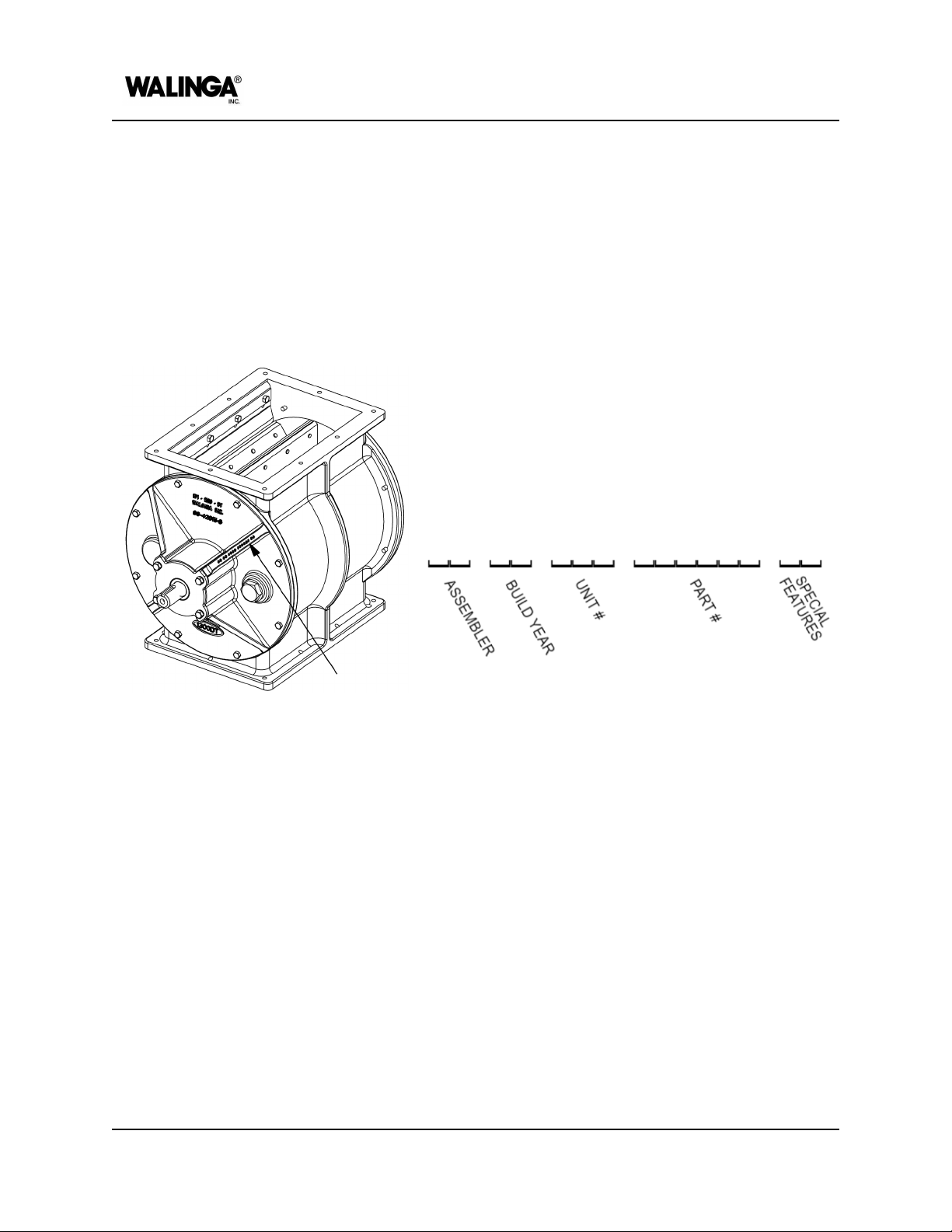
Your machine’s appearance or structural design may differ from illustrations shown in the
manual. Continuous design improvements for optimized field performance are on-going and
may have been made to your machine since the publication of the manual. Specifications,
descriptions and all other information in the manual are subject to change and/or correction
without notice. Contact your local dealer or Walinga representative for the most current revision
of your machine’s manual or if you have any questions.
INTENDED USE
The Walinga airlock has been designed for use in agricultural or similar operations. Use of the
machine in any other manner is considered as contrary to the intended use. Compliance with
and strict adherence to the methods of operation, maintenance, and repair, as specified by
Walinga in this manual, also constitute essential elements of the intended use.
The airlock must be operated, maintained and serviced only by persons who are familiar with its
particular characteristics and have been acquainted with the relevant safety procedures in this
manual. Any individual who has not familiarized themselves with the content of this manual is
considered untrained. Untrained persons are considered unqualified to operate, maintain or
service an airlock. It is the responsibility of the owner and/or operator to train new operators and
ensure they have read and understood this manual.
Accident prevention regulations, all other generally recognized regulations on safety and
occupational health and safety, and all road traffic regulations must be observed at all times.
Any unauthorized modifications carried out to the airlock may relieve Walinga of liability for any
resulting damage or injury and is considered contrary to the intended use.
2-2
00-144472-0 A
INTRODUCTION

OPERATOR’S MANUAL
DIRECTIONAL REFERENCES
To avoid confusion, the following directions will be used as a standard throughout the manual:
TOP
The inlet side of the airlock
BOTTOM
The outlet side of the airlock
FRONT
The driven end plate of the airlock
REAR
The non-driven end plate of the
airlock
LEFT
The left-hand side as viewed from
the FRONT of the airlock
RIGHT
The right-hand side as viewed from
the FRONT of the airlock
CCW
The standard counter-clockwise
rotational direction of the rotor
Figure 2-1: Directional references
AIRLOCKS IN PNEUMATIC CONVEYING SYSTEMS
Pneumatic conveying systems use air to move materials, Walinga’s airlocks are designed for
conveying common agricultural materials, such as cereal grains. The efficient operation
depends on many factors including air flows, line sizes, source power, operating methods, and
suction and discharge line arrangements, among others. Airlocks are used in a variety of
Walinga systems such as in Engineered Transportation Equipment in discharge and transfer
systems, as well as in Agri-Vacs, Central-Vacs, Ultra-Vacs, Ultra-Veyors, Silo-Fillers, and Barge
Unloaders.
A simplified representation of the function of an airlock in a pneumatic conveying system can be
seen in Figure 2-2 through Figure 2-4, showing both the drop-thru and blow-thru models. An
airlock acts as a seal between two sides of a pneumatic conveying system with a pressure
differential.
Product will enter the airlock from the top, either under vacuum or at atmospheric pressure. As
the airlock rotates, in a counter-clockwise direction as a standard, the upward facing pocket will
fill with material. The rotor will continue to rotate, allowing the next pocket to be filled, while
moving the filled pocket towards the bottom of the airlock. The tight clearances between the
blades or blade tips and the airlock casing create the seal between the different pressures of the
two sides of the system.
INTRODUCTION
00-144472-0 A
2-3

OPERATOR’S MANUAL
In the blow-thru model, as seen in Figure 2-2, a pressurized stream of air enters at the bottom
of the rear end plate. As the filled pockets rotate to the bottom, the product enters the
pressurized air stream and is carried through the outlet at the bottom of the front end plate to
the discharge side of the system. The motion of the discharged product is perpendicular to the
rotation of the airlock rotor. Blow-thru models will always function with a pressurized air stream
on the outlet side of the airlock, but can function with either vacuum or atmospheric pressure on
the inlet side.
Figure 2-2: Blow-thru style airlock
2-4
00-144472-0 A
INTRODUCTION

OPERATOR’S MANUAL
In the drop-thru model, as seen in Figure 2-3, a pressurized stream of air enters the product
collection device, commonly a pan or U-trough style. As the filled pockets rotate to the bottom,
the product falls into the collection device, entering the pressurized air stream, and is carried
through the conveying lines connected to the collection device. The motion of the discharged
product is parallel to the tangential direction of motion of the rotor blade tip at the bottom of the
airlock. For example, when viewed from the driven end of the airlock, the product would move
from left to right through the collection device with the standard counter-clockwise rotor rotation.
With a collection device and pressurized air stream connected to the outlet side of the airlock,
the inlet side will function under vacuum or atmospheric pressure.
Figure 2-3: Drop-thru style airlock with pressurized outlet
INTRODUCTION
00-144472-0 A
2-5

OPERATOR’S MANUAL
The drop-thru model, as seen in Figure 2-4, can also function with atmospheric pressure on the
outlet side. In this application, as the filled pockets rotate to the bottom, the product will fall into
a large collection device, such as a bin. With a system operating with atmospheric pressure on
the outlet side, the inlet side may be under vacuum, or atmospheric pressure if used as a
metering device.
Figure 2-4: Drop-thru style airlock with atmospheric pressure outlet
2-6
00-144472-0 A
INTRODUCTION

Machine
Configuration
AIRLOCK MODELS
3-1

OPERATOR’S MANUAL
MODEL SIZES
Walinga airlocks are available in a variety of sizes. To identify the size of your airlock, refer to
the embossed model label on the side of the airlock casing or on the face of the end plate as
seen in Figure 3-1.
Figure 3-1: Model identification
If your model does not have an embossed model size, refer to Table 3-1 for the reference
dimensions of each specific model for identification.
3-2
00-144473-0 A
MACHINE CONFIGURATION

OPERATOR’S MANUAL
Table 3-1: Airlock model sizes
Interior Casing
Diameter
Rotor Length
Inlet/Outlet
Diameter
Capacity
1314-4
12.9 in
(32.8 cm)
14.3 in
(36.3 cm)
4 in
(10.2 cm)
0.8 cu ft/rev
(23 L/rev)
1314-5
12.9 in
(32.8 cm)
14.3 in
(36.3 cm)
5 in
(12.7 cm)
0.8 cu ft/rev
(23 L/rev)
1618-6
16 in
(40.6 cm)
18.3 in
(46.5 cm)
6 in
(15.2 cm)
1.6 cu ft/rev
(45 L/rev)
1618-7
16 in
(40.6 cm)
18.3 in
(46.5 cm)
7 in
(17.8 cm)
1.6 cu ft/rev
(45 L/rev)
2018-7
20 in
(50.8 cm)
18.3 in
(46.5 cm)
7 in
(17.8 cm)
2.69 cu ft/rev
(76 L/rev)
2224-8
22 in
(55.9 cm)
24 in
(61.0 cm)
8 in
(20.3 cm)
4.44 cu ft/rev
(126 L/rev)
1008
10 in
(25.4 cm)
8 in
(20.3 cm)
N/A
0.28 cu ft/rev
(8 L/rev)
1210
12 in
(30.5 cm)
10 in
(25.4 cm)
N/A
0.55 cu ft/rev
(16 L/rev)
1314
12.9 in
(32.8 cm)
14.3 in
(36.3 cm)
N/A
0.8 cu ft/rev
(23 L/rev)
1618
16 in
(40.6 cm)
18.3 in
(46.5 cm)
N/A
1.6 cu ft/rev
(45 L/rev)
2224
22 in
(55.9 cm)
24 in
(61.0 cm)
N/A
4.44 cu ft/rev
(126 L/rev)
MACHINE CONFIGURATION
00-144473-0 A
3-3

OPERATOR’S MANUAL
MODEL VARIATIONS
GENERAL
BLOW-THRU (BT)
Product enters through the top of the
airlock (usually under vacuum) and is
forced out of outlet on the bottom edge of
the front end plate by a stream of
pressurized air entering from the rear end
plate. This style is better suited for lighter
products or where cross contamination is a
concern.
DROP-THRU (DT)
Product enters through the top of the
airlock and drops out through the bottom.
The inlet can be under vacuum or
atmospheric pressure, and the outlet can
be pressurized or at atmospheric pressure.
The pressurized air flow should be aligned
tangentially with the rotation of the rotor
blades. This style is better suited for
heavier products and can be used in
series with multiple airlocks.
3-4
00-144473-0 A
MACHINE CONFIGURATION

OPERATOR’S MANUAL
STANDARD PROFILE (-*A)
The standard profile for blow-thru airlocks
features a circular inner surface of the
casing, maintaining the same clearance
between the casing and rotor blade tips at
all points during rotation.
EXTENDED PROFILE (-*B)
The extended profile for blow-thru airlocks
features a lowered portion of the casing at
the bottom, creating an extra pocket of
space. This pocket allows for improved air
and product flow through the outlet of the
airlock. This variation is only available for
1314-5 airlocks.
MACHINE CONFIGURATION
00-144473-0 A
3-5

OPERATOR’S MANUAL
ABRASIVE (ABR)
Purge ports located in both end plates
provide continuous positive pressure to the
bearing cavity, preventing product buildup
in the bearing and seal area. This feature
is used when conveying abrasive materials
or powders to prevent premature wear and
damage.
HARD COATING (HC)
A hard coating is applied to the interior
machined surfaces of the casing and/or
end plates, providing improved wear
resistance.
HALAR COATING (HALAR)
Alternative coatings may be applied to the
interior machined surfaces of the casing,
end plates, and/or rotor blades and shaft.
These coatings provide corrosion and
abrasion protection as well as a
low-friction surface to prevent hang-up of
oily products.
3-6
00-144473-0 A
MACHINE CONFIGURATION
Table of contents
Other Walinga Industrial Equipment manuals
Popular Industrial Equipment manuals by other brands

Somex
Somex UA40H Technical document

PCB Piezotronics
PCB Piezotronics ICP J353B31 Installation and operating manual

ABB
ABB HT846964 Operation manual

Enerpac
Enerpac ECH-52 instruction sheet

PCB Piezotronics
PCB Piezotronics M352C66 Installation and operating manual

Kollmorgen
Kollmorgen RGM Programmer's guide