Allied HO-PAC 1000 Series User manual

TECHNICAL
MANUAL
Manual Part Number 103376
1000
SERIES
HO-PAC

1000 Series Ho-Pac
Allied Ho-Pac Model 1000 Series
Document Change Notice
Date Page Change
Jul 21, 2004 Original Issue
Aug 12, 2004 34-41 Change valve mounting bolts
Aug 27, 2004 34-41 Revise hose adapter
Oct 06, 2005 33 Correct adapter plate P/N
Jan 16, 2006 31 Revise 18 gpm valve P/N
Sep 29, 2006 25 Revise oil capacity
Oct 24, 2006 34-35 Revise bearing housing
Mar 16, 2007 7, 8, 9, 12, 13,
36, 37, 40, 41,
42, 43, 44, 45, New Eccentric, Eccentric Housing
May 01, 2008 36 Revise parts diagram

1000 Series Ho-Pac
TABLE OF CONTENTS
Section Page
SECTION 1.0 INTRODUCTION 1
1.1 Safety Information 1
1.2 Warranty Information 1
1.3 Allied Product Policies 1
SECTION2.0OVERVIEW 3
SECTION 3.0 PRINCIPLES OF OPERATION 4
3.1 Ho-Pac 4
3.2 Hydraulic Installation Definition 4
SECTION 4.0 TECHNICAL INFORMATION 6
4.1 Specifications 6
4.2 Dimension Diagrams 7
4.3 Decal Identification 10
4.4 Decal, Lifting and Lubrication Diagrams 12
SECTION 5.0 MOUNTING INFORMATION 14
5.1 USF Mounting 14
5.2 BSF Mounting 14
5.3 BR / SR Bracket Mounting 14
5.4 VMS V10 and V12 Mounting 15
SECTION 6.0 GENERAL CONSTRUCTION SAFETY 16
6.1 Owner’s Responsibilities 16
6.2 General Construction Safety 16
6.3 Federal, State, Local and OSHA Construction Guidelines and Regulations 16
6.4 General Safety Summary 16
6.4.1 CAUTIONS and WARNINGS 16
6.4.2 Personnel Precautions 17
SECTION 7.0 CARRIER APPLICATION 18
SECTION 8.0 INSTALLATION & REMOVAL 19
8.1 Installation 19
8.2 Removal 19

1000 Series Ho-Pac
TABLE OF CONTENTS (continued)
Section Page
SECTION 9.0 OPERATION 21
9.1 Preparation for Operation 21
9.2 Operation 21
SECTION 10.0 TROUBLESHOOTING 23
SECTION 11.0 SERVICE AND MAINTENANCE 24
11.1 General Guidelines 24
11.2 Daily Maintenance 24
11.3 Preventive Maintenance 24
11.4 Conditional Maintenance 25
11.5 Lubrication 25
11.5.1 How to Drain Oil 25
11.5.2 How to Check and Add Oil (including oil capacity) 25
11.5.3 Oil Pressure Relief Valve 25
11.6 Bolts 26
11.7 Bearing Failure & Replacement 26
11.7.1 Bearing Removal 26
11.7.2 Bearing Installation 27
11.8 Spring Mounts 27
11.9 Hydraulic Motor 27
11.9.1 Hydraulic Motor Service 27
11.9.2 Motor Rotation 27
11.9.3 Motor Identification 28
11.10 Hydraulic Control Valve 28
11.10.1 Control Valve Service 28
11.10.2 Valve Port Identification 28
11.11 Warranty Protection 28
SECTION 12.0 LIFTING & TRANSPORT 29
SECTION 13.0 STORAGE 30
SECTION 14.0 PARTS INFORMATION 31

1000 Series Ho-Pac
1
SECTION 1.0
INTRODUCTION
Ho-Pac Technical Manual: Part Number 103376
This Technical Manual is applicable to Ho-Pac models: 1000 series
Serial Numbers: 1000 and Above
Years of Manufacture: 2004 and Above
Serial Number(s)__________________________________ (Model and serial numbers are
located on the ID Plate mounted on the Ho-Pac as shown in Section 4.4 Decal, Lifting and
Lubrication Diagrams.)
This manual contains important
information for the safe use and
maintenance of the Allied Ho-Pac. Read
this manual thoroughly before installing,
operating or servicing the Ho-Pac. This
manual must be easily accessible to
operators, or service and transport
personnel. Store this manual in a
convenient location.
Pay careful attention to all instructions and
follow all governing regulations. Operation
or service other than in accordance with
these instructions may subject the Ho-Pac
to conditions beyond its design capability.
Improper operation, service or the use of
non-Allied parts may result in Ho-Pac
failure or personnel injury.
1.1 Safety Information
When using the Ho-Pac, safety procedures
must be followed. See Section 6.0 for
further safety guidelines.
Pay particular attention to WARNINGS
and CAUTIONS, identified with this
symbol. (!!)
These instructions are important for
personnel safety and full service life of the
Ho-Pac. Follow them carefully.
1.2 Warranty Information
Warranty coverage of the Allied Ho-Pac is
contingent upon proper maintenance and
operation of the Ho-Pac as detailed in this
manual. Improper maintenance or
operation shall void Ho-Pac warranty
coverage.
Immediately upon receipt of the Ho-Pac,
read all Allied warranty documents
delivered with the unit for a thorough
understanding of warranty coverage.
Record the Ho-Pac Serial Number in the
space provided above.
1.3 Allied Product Policies
Allied reserves the right to make
modifications to the design or changes to
the specifications without prior notice.
In this manual, Allied recommends Ho-Pac
applications, maintenance and service

1000 Series Ho-Pac
consistent with industry practices. Allied
takes no responsibility for the results of
action not recommended in this manual
and specifically the results of:
• Operation in non-recommended
applications
• Incorrect operation
• Improper maintenance
• Use of service parts not approved
or supplied by Allied.
These exclusions apply to damage to the
Ho-Pac, associated equipment, and injury
to personnel.
2

1000 Series Ho-Pac
SECTION 2.0
OVERVIEW
The Allied Ho-Pac is a boom-mounted,
hydraulic powered, vibrating plate
compactor and driver. It is used for soil
compaction and sheet/pile installation. The
Ho-Pac is typically mounted on either a
rubber tired or track construction vehicle.
The Allied 1000 series Ho-Pac is effective
in compacting materials up to 4 foot lifts.
Compaction results are dependent on soil
type, moisture content, compaction time
and operational technique. Soils with 50%
or more granular content are the most
responsive to vibration compaction.
Optimum moisture content is also critical
to achieving maximum compacted
densities of fill material. Fill materials
may need conditioning prior to
compaction.
The Allied Ho-Pac vibrating compactor
consists of the following major
subassemblies:
The DYNAMIC ASSEMBLY includes the
hydraulic motor, bearings, eccentric mass,
housing frame and base plate. This
assembly generates and transfers the
vibratory energy to the soil.
The SUSPENSION SYSTEM has spring
mounts that suspend and isolate the
Dynamic Assembly from the Mounting
Frame.
The MOUNTING FRAME houses the
Suspension System and mounts to the
boom of the carrier.
The HYDRAULIC CONTROL VALVE is
a multi-function, hydraulic control valve
that regulates hydraulic flow and protects
the Ho-Pac from excessive hydraulic
pressures and flows. The specific valve
functions are:
• Flow control: The valve limits the
oil flow to optimize Ho-Pac
operation and longevity. Excess
flow results in excessive motor
speed and shortens bearing and
motor life.
• Pressure control: The valve limits
the operating pressure to protect the
Ho-Pac motor from damage caused
by excessive pressure. The relief
pressure is pre-set to match the
motor’s maximum operating
pressure plus 200 psi (14 bar).
• Anti-cavitation circuit: The valve
controls the Ho-Pac motor and
eccentric deceleration. Without
this circuit, abrupt changes in the
return flow from the Ho-Pac to the
carrier can cause damaging
pressure spikes.
• Return line check valve: The valve
prevents reverse flow to the
hydraulic motor and provides a
nominal back-pressure to insure the
proper operation of carrier
mounted, flow control valves.
3

1000 Series Ho-Pac
SECTION 3.0
PRINCIPLES OF OPERATION
3.1 Ho-Pac
The Allied Ho-Pac is a high-energy
compaction tool utilizing three compaction
techniques:
• The IMPULSE FORCE generated
by the rotating eccentric mass
vibrates the soil near the base plate
to eliminate voids between material
particles.
• The VIBRATION FREQUENCY
of 2000 r.p.m. provides maximum
effectiveness for the consolidation
and compaction of granular soil
materials.
• The DOWN FORCE of the carrier
provides a preload force to
effectively transfer the vibrating
energy and to compress the
material.
Optimum compaction is usually obtained
with two passes. The duration of the initial
pass is dependent on depth and material.
The second pass may require additional fill
material and Ho-Pac repositioning to
achieve a finished surface.
The Allied Ho-Pac can also be an effective
sheet or pile driver. The Ho-Pac’s
vibration energy is transferred through the
sheet or pile to the soil. Sandy soils and
moist clays are “softened” by the vibration,
which allows the sheet or pile to penetrate
more easily.
3.2 Hydraulic Installation Definition
Efficient operation, production rates and
service life of Allied attachments depend
on the correct hydraulic oil flow and
pressures. Adjust the carrier's hydraulic
system accordingly during installation and
start-up. Among other important
information, the Allied technical
specifications include Hydraulic Flow,
Operating Pressure, Dynamic Relief
Pressure and Static Relief Pressure. These
parameters are defined as:
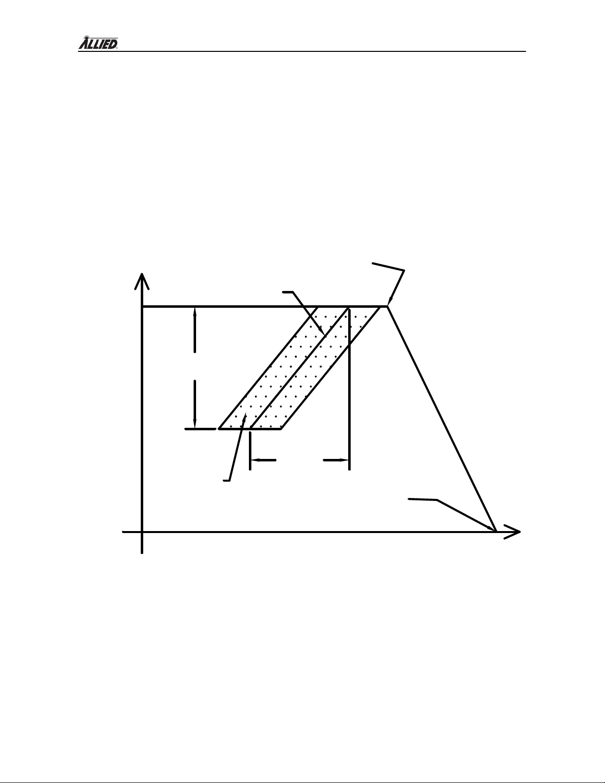
• HYDRAULIC FLOW is the
hydraulic oil flow range, minimum
to maximum, necessary for proper
attachment operation. Operating
the attachment outside this range
can result in inefficient operation,
damage to the attachment, or injury
to personnel.
• HYDRAULIC OPERATING
PRESSURE is the average
hydraulic oil pressure measured at
the attachment during operation.
The Hydraulic Operating Pressure
range is the range of pressure
required to operate the attachment
throughout the Hydraulic Flow
range. The Operating Pressure is
not to be used as a relief valve
pressure setting.
• DYNAMIC RELIEF PRESSURE
is the hydraulic oil pressure when
the relief valve starts to open and
divert oil back to the carrier instead
of the attachment. The carrier's
hydraulic system shall be capable
of providing the desired oil flow at
a pressure equal to at least the
dynamic relief pressure. Also it is
very important not to control the oil
flow with the relief valve. This
may cause significant heat
4

1000 Series Ho-Pac
generation and damage the
attachment and/or carrier.
• STATIC RELIEF PRESSURE is
the hydraulic oil pressure when all
oil flow is diverted through the
relief valve and away from the
attachment. The attachment must
never be subjected to pressures
above the static relief pressure.
The difference between static relief
pressure and dynamic relief
pressure varies with relief valve
design. In some instances, the
relief valve may be inadequate to
divert full oil flow at less than the
Static Relief Pressure. If this is the
case, contact your local Allied
dealer for assistance.
FLOW
PRESSURE
Hydraulic
Flow Range
Operating
Pressure
Range
Static Relief Pressure
(No flow to attachment)
Dynamic Relief Pressure
(Begin flow through relief valve)
Attachment
Operational
Range
Operating Pressure
Figure 3.1: Flow-Pressure Diagram
5

1000 Series Ho-Pac
SECTION 4.0
TECHNICAL INFORMATION
4.1 SPECIFICATIONS
Table 4.1
Ho-Pac General Specifications
Impulse Force Lbs (N) 8,000 (35,586)
Cycles Per Minute 1/min 2000
Sound Power Level DBA (LWA) 105.6
Hydraulic Flow Motor Option 1 12 (45)
Motor Option 2 18 (68)
gpm (lpm)
Motor Option 3 21 (79)
Operating Pressure-No Load psi (bar) 300-1000 (20-35)
Max Operating
Pressure Motor Option 1 2800 (193)
Motor Option 2 2000 (138)
Motor Option 3
psi (bar)
2000 (138)
Carrier Dynamic Relief Pressure psi (bar) Max Operating + 400 (28)
Carrier Static Relief Pressure psi (bar) Max Operating + 650 (45)
Compaction Plate Dimensions (Std) 24 x 32.5 (61 x 83)
Compaction Plate Dimensions (Option) Inch (cm) 16 x 36.0 (41 x 91)
Compaction Area (Std) 5.4 (0.50)
Ft2(m2) 4.0 (0.37)Compaction Area (Option)
Pressure Hose Size Inch (mm) 3/4 (16)
Return Hose Size Inch (mm) 3/4 (16)
Recommended Carrier Weight
Backhoe 9,000-25,000 (4,000-11,000)
Lbs (kg) 14,000-30,000 (6,000-14,000)Excavator
Table 4.2
Ho-Pac Mounting Specifications
USF BSF BR / SR V10 V12
Weight 1053 (478) 1053 (478) 1034 (469) 1018 (462)
Lbs (kg) 1020 (463)
Mounting Pin
Diameter
Inch (mm)
1.18-2.25
(30-57) 1.75 & 1.50
(44.5 & 38) Varies 1.18-2.56
(30-65) 1.18-2.56
(30-65)
Maximum Stick
Width
Inch (mm) 10.23 (260) 10.25 (260) Varies 10.12
(257) 12.50
(317)
6

1000 Series Ho-Pac
4.2 DIMENSION DIAGRAMS
Figure 4.1: USF Ho-Pac Dimensions
Figure 4.2: BSF Ho-Pac Dimensions
7

1000 Series Ho-Pac
Figure 4.3: BR / SR Ho-Pac Dimensions
8

1000 Series Ho-Pac
Figure 4.4: VMS V10 Ho-Pac Dimensions
Figure 4.5: VMS V12 Ho-Pac Dimensions
9

1000 Series Ho-Pac
4.3 DECAL IDENTIFICATION
The ID PLATE (Identification Plate) contains the following information: Manufacturer’s
name and address, Product Name, CE compliance marking, Model Number, Serial Number,
Year of Manufacture, and Mass.
The LIFT POINT decal identifies the location of the recommended lifting points of the Ho-
Pac.
The STAY CLEAR decal indicates that personnel and by-standers are to maintain a safe
distance from the Ho-Pac during operation.
The READ INSTRUCTION decal indicates that it is important for the operator to read the
manual prior to transporting, installing, operating, or servicing the Ho-Pac.
The HOT SURFACE decal indicates that the hydraulic components may be hot and that
proper protective equipment is required. These components include the quick disconnect
couplings, hoses, hose fittings, and hydraulic motor.
10

1000 Series Ho-Pac
The ALLIED LOGO decal is the Allied brand identifier and is a registered trademark of
Allied Construction Products, LLC.
The PRESSURE I.D. tag is attached to the pressure hose for ease of identification between
hoses.
1000
The MODEL NUMBER decal indicates the Ho-Pac model number.
ALLIED 102728
The OIL FILL decal identifies the location to add oil to fill the oil reservoir. Refer to Section
11.5 for more information.
allied 102729
The OIL LEVEL decal identifies the location to check the oil level. Refer to Section 11.5 for
more information.
11

1000 Series Ho-Pac
4.4 DECAL, LIFTING and LUBRICATION DIAGRAMS
Figure 4.6: USF & BSF Ho-Pac Decal Locations
Figure 4.7: BR / SR Ho-Pac Decal Locations
12

1000 Series Ho-Pac
Figure 4.8: VMS V-10 & V-12 Ho-Pac Decal Locations
Table 4.3
Decal Parts List
Part No. 103377
ITEM QTY PART No. DESCRIPTION
1 1 676980 ID Plate
2 4 676982 Lift Point
3 2 676981 Stay Clear
4 2 676984 Read Instructions
5 1 676983 Hot Surface
6 2 676653 Allied Logo
7 1 102728 Oil Fill
8 1 A102729 Oil Level
9 2 103378 Model 1000
10 1 818676 Pressure I.D. Tag (Located on Pressure Hose)
13

1000 Series Ho-Pac
14
SECTION 5.0
MOUNTING INFORMATION
5.1 USF Mounting
Allied USF mounting kits include all the
components necessary for the mechanical
installation of the USF style Ho-Pac. A
typical kit consists of two mounting pins,
four flange bushings or collars, and pin
retaining hardware. Mounting kits are
purchased separately.
Flange
Bushing Spacer Sleeve
Bushing Pin
Mounting
Possible Configurations.
All components are installed inside the HoPac frame.
These items may be included with Mounting Kit.
Since the pin center-to-center distance is
fixed, quick couplers may not be possible
when using the USF configuration. The
following illustration shows the contents of
a typical USF Mounting Kit.
5.3 BR or SR Mounting
The flat top style Ho-Pac is mounted to a
specific carrier by using an adapter bracket
that is bolted to the Ho-Pac top plate.
Brackets are available for either mounting
type and are designed to match the carrier
requirements. A typical bracket is shown
below.
5.2 BSF Mounting
Allied BSF mounting kits include all the
components necessary for the mechanical
installation of the BSF style Ho-Pac. The
kit is supplied in one of the configurations
shown below.
In configurations #2, 3, 4, 5 & 6, the kit
includes bushings that fit into the carrier
stick and link. These bushings are
necessary to adapt to the smaller diameter
pins supplied in the kit.

1000 Series Ho-Pac
5.4 VMS Mounting
The combination of the VMS frame design
and a VMS mounting kit provides
unequaled versatility and ease in attaching
the units to carriers, and in transferring a
Ho-Pac from one carrier to another. The
typical VMS mounting kit contains two
collars, two plugs, and two pins as shown
in the diagram below. The VMS Ho-Pac
design is easily adapted to most quick
couplers.
15

1000 Series Ho-Pac
SECTION 6.0
GENERAL CONSTRUCTION SAFETY
6.1 Owner’s Responsibilities
The equipment owner shall:
• Provide this technical manual to the
Ho-Pac operators.
• Train all operating personnel and
enforce the procedures explained in
this manual, especially regarding
safety to personnel and equipment.
• Adapt these general instructions to
specific applications.
6.2 General Construction Safety
Follow standard safety precautions
expected and required of those working in
construction, including but not limited to,
locating existing underground service and
utility lines, establishing pedestrian
barriers and using personnel protection
equipment, etc.
6.3 Federal, State, Local and OSHA
Construction Guidelines and
Regulations
Use the Ho-Pac in accordance with all
federal, state and local regulations
regarding construction practices and public
safety. Identification of, and compliance
to, governing regulations are the
responsibility of the owner and operator.
In the United States, comply with the
recommendations of the Occupational
Safety and Health Administration
standards of the U.S. Department of Labor.
For OSHA construction guidelines contact
your local federal government office or
write:
U.S. Government Printing Office
Superintendent of Documents
P.O. Box 371954
Pittsburgh, Pa. 15250
Ask for Construction Industry OSHA
Standards Stock #869-034-00107-6.
6.4 General Safety Summary
The safe and effective use of any heavy
construction equipment depends upon
proper installation, operation, maintenance
and repair. Operational safety must
encompass all of these factors. This
Section includes minimum safety policies
the Ho-Pac owner shall establish for all
Ho-Pac installations. The Ho-Pac owner
shall define safety procedures to meet site
and application conditions. Such
procedures result in increased equipment
life and performance and reduced
downtime. Most importantly, it will reduce
the risk of equipment damage and
personnel injuries.
6.4.1 Cautions and Warnings
Throughout this manual detailed
CAUTIONS and WARNINGS are
included with instructions and procedures.
Even experienced service technicians are
to review these CAUTIONS and
WARNINGS prior to performing a
procedure. CAUTIONS and WARNINGS
are highlighted by the symbol shown here
(!!) and explained as follows:
!! WARNING !!
Instructions preceded by this symbol
identify hazards to personnel.
16
Table of contents
Popular Industrial Equipment manuals by other brands

Siemens
Siemens 3AF 01 Operating instructions manual

AuCom
AuCom PROFINET CARD instructions

Wilo
Wilo Stratos GIGA2.0-I Installation and operating instructions

STABILUS
STABILUS ACE TUBUS TR-L Operating and mounting instructions

Bühler technologies
Bühler technologies Smart-Sample-Tube Brief instructions

Timken
Timken Rollon Tecline Use and maintenance