Allied Solar Pty Ltd
7
P-MAN-01-1a_Rev B Installation, Operation and Maintenance Manual – AS-2560
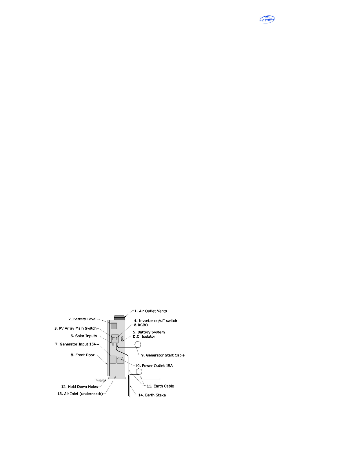
1. Air Outlet Vents: The unit has cooling air flowing in the mesh screen underneath and out of the
vents at the top. Care should be taken to ensure these vents are not obstructed or blocked in any
way.
2. Battery level: indicator shows critical battery information such as battery level, charging rate and
battery voltage. Note that the batteries have a very flat voltage curve and so the voltage is not a
reliable indicator of the remaining capacity unless the batteries are almost full or almost empty. The
capacity shown is calculated from the charging / discharging current which is the most accurate
method but even this can become inaccurate sometimes. The calculated capacity is reset to 100%
each time the batteries become full.
3. PV Array Main Switch: The PV Array Main Switch disconnects the solar panels from the components
inside the AS-2560. Always disconnect the solar panels before disconnecting the batteries.
4. Inverter on/off switch: Turns the inverter off. If a back-up generator is connected then turning the
inverter off will trigger the unit to switch over to generator mode.
5. Battery System DC Isolator: This will disconnect the positive side of the battery from the inverter.
The PV panels must be disconnected using the PV Array Main Switch before switching this off.
Failing to do this may damage the AS-2560.
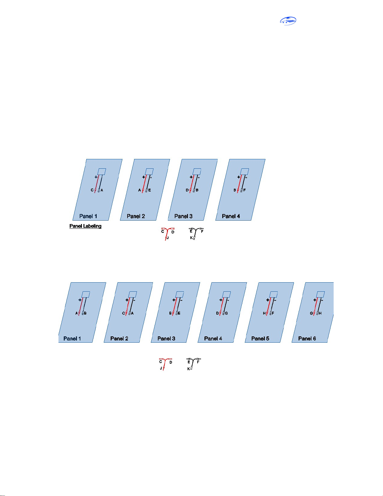
6. Solar Inputs: The solar panel strings are to be wired according to the PV wiring diagram and the 10m
PV extension cables plug into these input connectors. There are male and female plugs for the
positive and negative leads.
7. Generator Input: If the generator interface option is included then this is where the generator
power cable plugs into the Allied Solar AS-2560 System.
8. Front Door: provides access to the internal components of the off grid cabinet. Follow the
guidelines when accessing the inside of the compartment.
9. Generator start cable: plugs into the generator and provides a start signal to the generator (volt free
relay contacts close to start the generator). A 15m cable is provided with the generator interface
option.
10. Power Outlet: is a 15A GPO power outlet that is protected by 25A breaker and residual current
device (RCD). The outlet is connected to the inverter during normal operations and is switched to
the generator power when the AS-2560 switches to generator mode (if installed). There is a delay of
a few seconds when switching from one power source to the other where there is no power
available at the outlet.
11. Earth cable: The coil of earth cable is to follow the PV extension cables and connect to the framing
of the solar array. It is important that the earth wiring is completed correctly to ensure the earth
leakage protection device (RCD) works correctly and helps protect people from electrocution. Refer
to the installation section.
12. Hold down bolt holes: for securing the off grid cabinet to the ground and prevent from being
knocked over. The unit can also be secured to a wall using the bolt holes in the back of the unit near
the top corners.
13. Air inlet: is located under the off grid cabinet between the legs. Ensure there is good air flow under
the unit and the vents do not become blocked.
14. Earth stake: must be hammered into the ground near the load (cabin, caravan, house..). Ensure the
earth cable is not damaged and remains connected to the off grid cabinet.
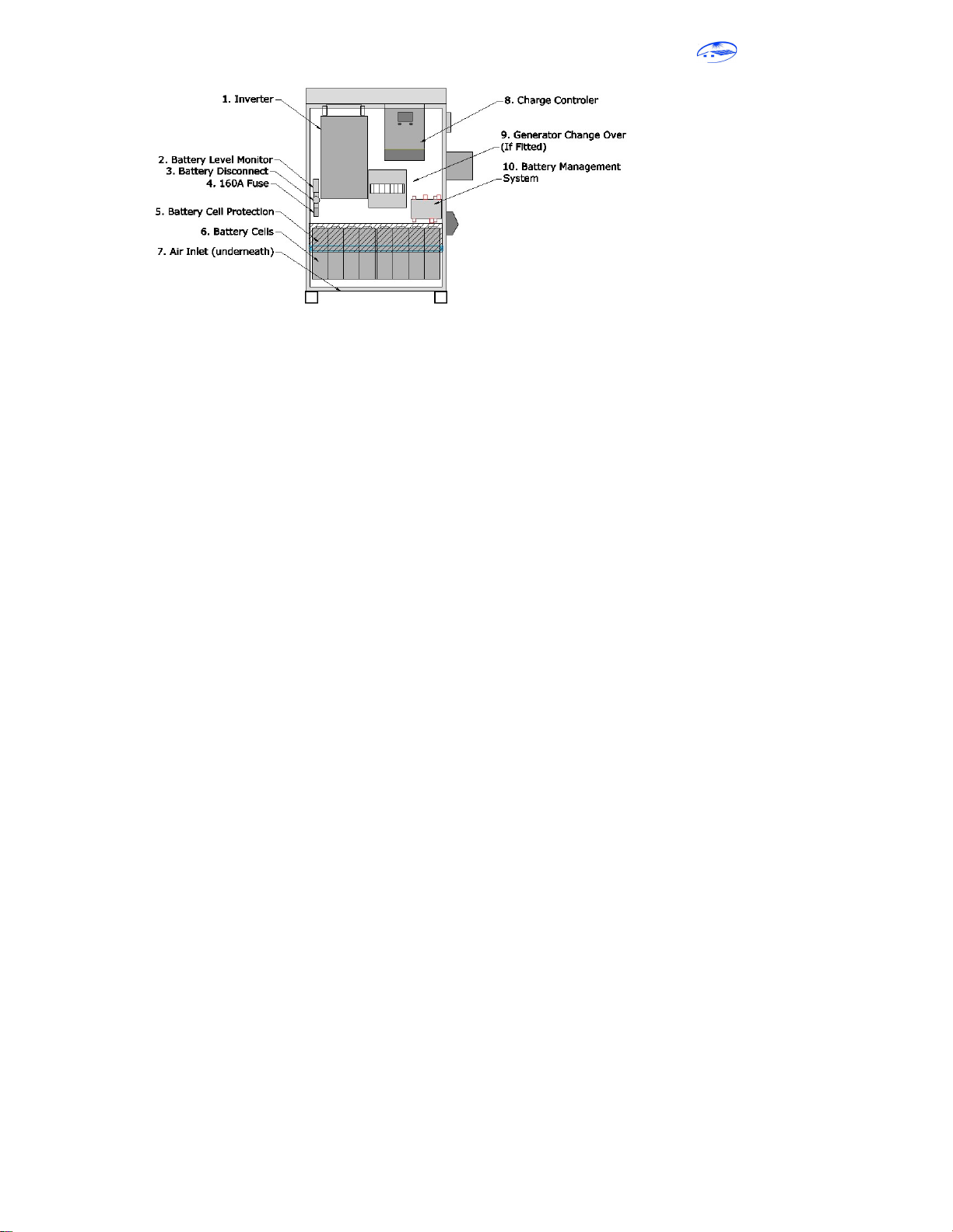
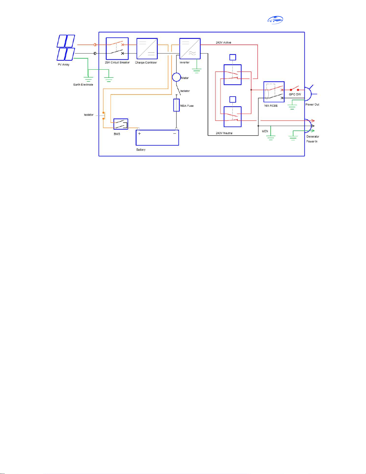
3.3 Internal Features of the Off Grid Solar Unit