Allis-Chalmers AD 30 User manual
t>
,
J
'\
l·
l~~
I~
j...
1\
II

FOREWORD
This book is written for the purpose of giving the operator
essential information regarding 'the day-to-day care,-lubrica-
tion and adj'l:1.stmentof the gra der, Economicaloperation'will
be ensured if these instructions' are followed.' .' ,
The instructions given i'nth
i
s book cover' the operation of tlie
I~llis-Chalmers" Models AD-30 and AD-40 Motor Graders ..'
close adherence to these instructions ~ill result in many hours
of trouble-free operation a,nda longer .operating life for the unit.
If II' ".
Many owners of :Allis-Chalmers equipment employ the Dealerts
·.Service Department for all work other than routine care and
adjustments. This practice is .encouraged as our dealers aj-e
\ kept well informed by the factory regarding advanced methods
of servicing ''Allis-Chalmers''.products, and are equipped to
render satisfactory service. ' .
*
**
All photographs shown throughout this manual 'a-re of the Model
AD-40 Motor Grader, unless otherwise stated. (Model AD-3,O
Motor Grader similar.)
,
,
ADJUSTMENTS
Ball
&
Socket Joints
Circle Guide ••
Clutch Brake. ~ ••
Clutch Linkage ...
'Control Shaf t.B'rak e
Engine Control.
Governor
Parking Brake.
Power 'I1ake-Off Chain.
Power Take-Off Drive Hou s
i
ng
Steering Mechanism.'
'Tandem Drive Chain:
Valves • " ••• " •
'Wheel Brakes .•.
Worm Shaft Bearing
Air Cleane.r ••.••..
Air Pre-Cleaner • ~ • . • '.
Avoid Unnecessary Engine Idling
Ball
&
Socket Joint Adjustment
Batteries ••• ' .•••••.•.
Circle Guide Adjustment ..
Clutch Brake Adjustment •.
Clutch Linkage Adjustment .
Cold Weather Engine Primer
Cold Weather Operation ..•
'Contr~ls
&
Instruments, Operating
Control Shaft Brake Adjustment.
Cooling System, Engine
Description, General. ~
Driving Instructions
Electrical System
Generator
.
,
.
ENGINE
Controls, Adjustment
Cooling System" . • •
Idj ing , Unnecessary
Lubrica tion System '.•
Serial Number. :' •
Starting
Stopping
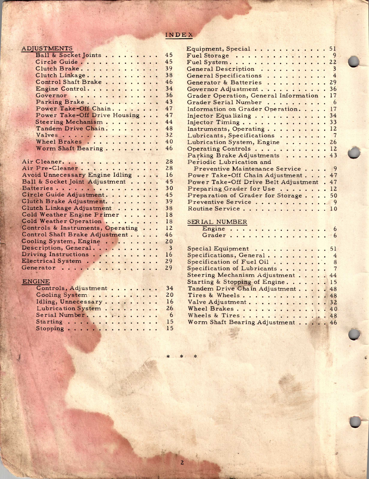
INDEX
45
45
39
38
46
34
36
43
47
47
44
48
32
40
46
Equipment, Special
Fuel Storage
Fuel System.
General Description
General Specifications
Generator
&
Batteries
Governor Adjustment.
Grader Operation, General Information
Grader Serial Number .
Information on 'Grader Operation.
Injector Equalizing
Injector Timing.. •
Instruments" Operating.
Lubricants, .Spec
if
i
cat i.ons
Lubrication System, Engine
Operating Controls
Parking Brake Adjustments
Periodic Lub r
i
cat
i
on and
Preventive Maintenance Service
Power Take-Off Chain Adjustment
Powe r Take-Off Drive Belt Adjustment
Preparing Grader for Use .•
Preparation of Grader for Storage
Preventive Se rvice
Routine Service.
28
28
16
45
30
45
39
38
18
18
12
46
20
3
16
29
29
SERIAL NUMBER
Engine
Grader
Special Equipment
Specifications, General
Specification of Fuel Oil
Specification of Lubricants
Steering Mechanism Adjustment
Starting
&
Stopping of Engine.
Tandem Drive <7;hainAdjustment
Tires
&
Wheels.
Valve Adjustment.
Wheel Brakes .••
Wheels
&
Tires ..
Worm Shaft Bearing Adjustment
34
20
16
26
6
15
15
*
*
r
*
51
9
22
3
4
29
36
17
6
17
34
33
12
7
26
12
43
9
4-7
47
12
50
9
10
,'_
51
4
8
7
44
15
48
,I
48
32
40_
'4$
46

r
GENERAL DESCRIPTION
CONTROL LEVERS
...J
f·
The ''Allis -Chalme rs
If
AD Motor Graders are
available in two models: The AD-30 Motor
Grader, a 22,700 pound unit, and the AD-40
Motor Grader, a 23,000 pound unit. These
graders are designed for use in construction
and maintenance of roads, general grading, and
snow removal. The main frame is of tubular
construction to provide the utmost strength and
rigidity and to provide unobstructed vision for
the operator.
The Model AD-30.is powered with a 3 cylinder,
2 cycle Diesel Engine and the Model AD-40 is
powered with a 4 cylinder, 2 cycle Diesel Engine.
Power from the engine is transmitted through
the engine clutch to the transmission and from
the transmission to the tandem drive shafts.
The tandem wheels are driven by heavy roller
chains which connect the sprockets on the wheel
shafts with the sprockets on the tandem drive
shafts.
T he rea
l'
wheels of the tandem drives are
equipped v.:ith hydraulic brakes. A lever con-
trolled, disc type, mechanical brake assemb~ed
to the transmission, is provided for a
pa
rking
b~ake.
The transmission on leach model is co'ntrolled
by two gear shift levers which provide 6 forward
and 3 reverse speeds. At full governed engine
speed of 1600r.p.m., the forward speeds on each
model range from 2.37 to 16.64 m.p.h. and the
reverse speeds range from 2.82 to 6.13 m.p.h.
,A mechanical control box with six control levers
for operating the moldboard, front wheel lean,
and scarifier or snow plow is located directly
in front' of the operator. The moldboard can be
rotated a full 360 degrees, thereby allowing
wo
rk
to be done with the machine traveling backw?-r.d
as well as forward. The moldboard can be tilted
to several different pitch positions to obtain the' .
desired rolling or cutting action and can also be
shifted out to either side for cutting ditches' ~'r"
sloping banks. The front wheels can be leaned
25.5 degrees to right or left to counteract side'
draft. A HYDRAGUIDE*steering system is pro _
vided for steering the grader. The arched fr ont
axle permits the handling of heavy windrows
of dirt, gravel, or .oil mix material. Provision
is made for mounting and operating special
equipment such as a scarifier or snow plow.
*HYDRAGUIDE is a trademark of Gemmer
Mfg. Co.
TURN GEAR HOUSING
!'lEAD CASTING
,
.
CIRCLEGUIDES DRAWBAR BALL AND SOCKET
3
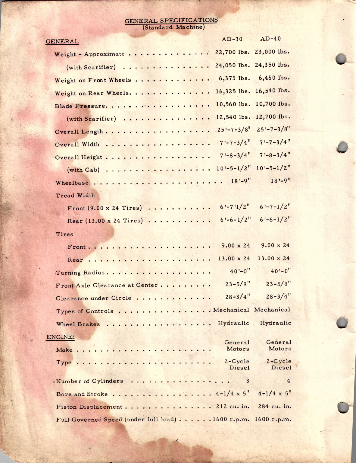
GENERAL SPECIFICATIONS
(Standard Machine)
GENERAL
Weight,.. Approximate • • .
(with Scarifier)
Weight on Front Wheels
.
_
Weight on Rear Wheels•
Blade' Pressure •.•
• .1;,. • •
....
(with Scarifi.er]
,
.'
Overall Length.
'Overall Width
.
..
.
.
.
Overall Height
(with C~b)
Wheelbase .
Tread Width
Front (9.00 x 24 Tires)
;~
Rear (13.00 x'24 Tires)
Tires
Front.
Rear •
_-T'urning Radius.
Front Axle ,Clearance at Center.
Clearance under Circle
Types of Controls
Wheel Brakes
ENGINE:
Make
Type
-Nurnbe
r of Cylinders
Bore and Stroke . . .
Piston Displacement.
Full Governed Speed (under full load)
AD-30 AD-40
22,700 lbs. 23,0001bs.
.
.
.
24,050 lbs, 24,350 lbs ,
6,375 lbs. 6,460 Ibs,
l6,325lbs. l6,540lbs.
10,560 lbs, 10,700lbs.
·12,5-40lbs. l2,700lbs •
25'-7 -3/8" 25'-7-3/8"
7'-7.,.3/4" 7'-7-3/4"
7'-8-3/4" 7'-8-3/4"
10'-5-1/2" 10'-5-1/2"
18'-9" 18'-9"
..
6'-7'1/2" 6'-7-1/2"
6'-6-1/2" 6'-6-1/2"
9.00 x 24 9.00 x 24
13.00 x 24 13.00 x 24
40'-0" 40'-0"
23-5/8" 23-5/8
11
28..;.3/4" 2.8-3/4"
. Me.chanica1
Me c ha n ic a l
Hydraulic Hydraulic
General General
Motors Motors
2-Cycle Z-Cycle
Diesel Diesel
34
4-1/4 x 5" 4-1/4 x 5"
212 cu. in. 284 cu. in.
.1600
rvp.rn ,
1600 r.p.m.
.
-
4
This manual suits for next models
1


