Allmand MAXI-LITE V Series User manual

11
ML 7.5/ML 8
OPERATOR’S MANUAL
ALLMAND BROS. INC
P.O. BOX 888
HOLDREGE, NE 68949
PHONE: 308/995-4495, 1-800/562-1373
ALLMAND FAX: 308/995-5887
ALLMAND PARTS FAX: 308/995-4883
MAXI-LITE SERIES
MAXI-LITE V-SERIES
For Parts and Updates visit Allmand on the Web at www.allmand.com
Part No. 106775

2
2
INSPECTION CHECK LIST
FOR PREPARING THE MAXI LITE FOR DELIVERY OR RENTAL
The MAXI LITE V-SERIES requires service as well as proper operation in order to provide
the performance and safety it has been designed for. Never deliver or put a machine into
service with known defects or missing instructions or decals. Always instruct the customer
in the proper operation and safety procedures as described in the operator’s manual. Al-
ways provide the manual with the equipment for proper and safe operation.
CHECK LIST:
Visually inspect the equipment to ensure that all instructions and decals are in place and
legible.
Inspect the tower latch and knob assembly which locks the tower in the vertical position
for proper operation
Check the hitch assembly and safety tow chains
Check the outriggers and jacks to make sure they operate properly
Inspect the light assemblies for damage and test for proper operation
Inspect the electrical wiring for signs of damage
Check the ground rod cable and the ground lug. Make sure they are clean, undam-
aged, and functional.
Inspect the tires to ensure good condition and proper ination
Check oil, fuel, coolant levels, and hydraulic uid levels.
Check to make sure the operator’s manual is with the equipment.
Inspect the machine physically for damage and repair if necessary.
Inspect the light bar and latch in transport position.
NOTE: See appropriate section of manual for scheduled maintenance intervals.
After completing the inspection check list, operate the tower through a complete op-
eration cycle, following the operating instructions in the operator’s manual.
WARNING
NEVER ALLOW ANYONE TO OPERATE THE EQUIPMENT WITHOUT
PROPER TRAINING!
ALWAYS READ THE INSTRUCTIONS FIRST!

2
23
INSPECTION CHECK LIST........................................................................................................2
TABLE OF CONTENTS..............................................................................................................3
INTRODUCTION.........................................................................................................................4
SAFETY SYMBOL INFORMATION............................................................................................4
SAFETY AND WARNING DECALS........................................................................................ 5-7
HYDRAULIC LIFT MAST OPERATION ............................................................................... 8-10
TOWING AND STARTING INSTRUCTIONS .......................................................................11-12
SERIAL NUMBER LOCATION .................................................................................................13
SPECIFICATIONS............................................................................................................... 14-16
CONTROLS AND COMPONENTS..................................................................................... 17-24
ROUTINE MAINTENANCE SCHEDULES................................................................................25
TROUBLESHOOTING..............................................................................................................26
ASSEMBLY PARTS AND ACCESSORIES ..............................................................................27
TABLE OF CONTENTS

4
4
This manual provides the information necessary for the safe operation of the Allmand
Bros., Inc., MAXI-LITE V-SERIES light tower.
The MAXI-LITE V-SERIES standard tower is operated with a 12 VDC hydraulic pump
and hydraulic cylinder.
Specic operating instructions and specications are contained in this publication to fa-
miliarize the operator and maintenance personnel with the correct and safe procedures
necessary to maintain and operate the equipment.
Take time to read this book thoroughly. If you are uncertain about any of the information
presented in the manual, contact the factory or your dealer for clarication before operation.
INTRODUCTION
The purpose of the SAFETY INFORMATION SYMBOL shown below is to attract your spe-
cial attention to safety related information contained in the text.
DANGER
WARNING
CAUTION
FAILURE TO UNDERSTAND AND COMPLY WITH SAFETY RELATED INFORMATIONAL
INSTRUCTIONS MAY RESULT IN INJURY TO OPERATOR OR OTHERS. IF YOU DO
NOT UNDERSTAND ANY PART OF THIS INFORMATION CONTACT YOUR DEALER
FOR CLARIFICATION PRIOR TO OPERATING EQUIPMENT.
NOTE
The word NOTE is used to bring your attention to supplementary information in relation to
various aspects of proper operation and maintenance.
NOTE: Keep this manual accessible during operation to provide convenient reference.
NOTE: Any reference in this manual to LEFT or RIGHT shall be determined by looking at
the trailer from the rear.
SAFETY SYMBOLS

4
45
SAFETY AND WARNING DECALS
SAFETY WARNING
ALWAYS REPLACE ANY SAFETY AND INSTRUC-
TION DECALS THAT BECOME DAMAGED, PAINT-
ED, OR OTHERWISE ILLEGIBLE.
Refer to these representations of the safety
warning decals used on the MAXI-LITE to
insure correct ordering if replacing be-
comes necessary.
PART NO. 090307
Location: Inside left hand
door panel of Caterpillar en-
gine units.
PART NO. 090249
Location: Inside left hand
door panel of Kubota engine
units.
PART NO. 101925
Location: Inside left hand door panel.

6
6
SAFETY AND WARNING DECALS
PART NO. 090158
Location: AC control panel
PART NO. 090166
Location: Inside left hand
door panel
PART NO. 090163
Location: On left side
wheel well
PART NO. 090165
Location: Inside left hand
door panel
PART NO. 090084
Location: AC control panel PART NO. 090162
Location: On left front
enclosure panel
PART NO. 090133
Location: On left side panel below
ground lug
PART NO. 090159
Location: On right hand
wheel well
PART NO. 090226
Location: Left front
panel.
PART NO. 090034
Location: On left inner fender
adjacent to fuel tank ller neck

6
67
SAFETY AND WARNING DECALS
PART NO. 101057
Location: On fuel tank near ller neck.
PART NO. 090465
Location: Inside left door panel.
PART NO. 100247
Location: Inside left door panel.
PART NO. 090179
Location: On fuel tank near ller neck.
PART NO. 101404
Location: On either side of mast assembly
immediately above roof panel .
PART NO. 090306
Location: On AC
control panel
PART NO. 090160
Location: On trailer drawbar near
revsible hitch assembly.
PART NO. 090002
Location: On light bar
assembly PART NO. 090005
Location: Inside left door panel

8
8
HYDRAULIC LIFT VERTICAL MAST OPERATION
DESCRIPTION OF OPERATION
The Allmand MAXI-LITE V Series hydraulic
lift tower assembly consists of a seven sec-
tion telescoping mast which can be extended
by operating a single hydraulic cylinder.
The light bar assembly can be rotated into
position by releasing the light bar park pin.
To release the park pin, pull the ring and turn
it 90 degrees so that the pin remains in the
retracted position. The light bar is designed
to rotate with enough resistance so that the
bar will stay in the desired position once the
operator has directed the lights on the work
zone. if the light bar rotates too easily or does
not stay in position, remove the cap plug from
the center of the light bar cover and tighten
the nut to achieve the desired resistance and
replace the cap plug.
ALWAYS CHECK FOR OVERHEAD OB-
STRUCTIONS BEFORE RAISING AND
LOWERING MAST. ALLOW 35' CLEAR-
ANCE. AVOID ALL OVERHEAD ELECTRI-
CAL WIRES.
TO PREVENT INSTABILITY AND HELP
ENSURE SAFE OPERATION, ALWAYS
PROVIDE PROPER GROUND SUPPORT
BEFORE RAISING MAST.
TO SET UP TOWER AND RAISE
LIGHTS
1. Extend both side outrigger jacks, rear jack
and tongue jack to stabilize and level the
trailer.
NOTE: Jacks should be placed only on
rm footing.
BEFORE RAISING MAST, VISU-
ALLY INSPECT EQUIPMENT FOR
DAMAGE OR WEAR. FAMILIARIZE
YOURSELF WITH THE LOCATION
AND FUNCTION OF ALL OPERAT-
ING PARTS BY STUDYING THIS
MANUAL. OBSERVE ALL CAU-
TION DECALS LOCATED ON
EQUIPMENT
SAFETY WARNING!
SAFETY WARNING!
THE SUPPLEMENTAL GROUND ROD IS
A SAFETY DEVICE THAT MAY REDUCE
THE CHANCE OF PERSONAL INJURY
FROM STRAY ELECTRICAL CURRENT.
Therefore, Allmand recommends using
the ground rod. However, it is the user’s
responsibility to determine the require-
ments and/or applicability of local, state,
or national electrical code which governs
the use of the ground rod.
2. Attach the ground rod to the grounding lug,
and drive the ground rod fully for adequate
electrical ground, as required by local, state,
or national code.
3. Start engine.(NOTE: Tower may be raised
and lowered as needed without engine run-
ning.)
4. While the tower is still in the down position,
position the light bar and lamps so they are
aimed at the work zone and tilted at the ap-
proximate angle to get maximum coverage
once the tower is raised.
5. Stand clear of the tower when raising and
lowering the lights.

8
89
HYDRAULIC LIFT VERTICAL MAST OPERATION
VISUALLY INSPECT EQUIPMENT FOR
DAMAGE BEFORE OPERATING. ALLOW
ADEQUATE CLEARANCE AROUND TRAIL-
ER FOR TOWER AND INSURE THAT NO
PERSONS ARE STANDING IN UNDER THE
LIGHTS WHEN LOWERING.
TO LOWER TOWER AND LIGHTS
1. Turn off lights.
2. Operate the hydraulic lift switch in the down
position to lower the lights to the lowest
vertical position. When tower reaches
the bottom, run switch for three additional
seconds to ensure that the tower is at it’s
lowest possible position.
3. Stop engine.
4. Rotate the light bar into the transport park
position (in line with trailer) and engage the
park pin by twisting on the park pin ring until
the plunger is released and the pin engages
the hole in the light bar.
SAFETY WARNING!
6. Operate the hydraulic lift switch to the
“up” position to raise tower to the de-
sired height.
7. If lights need to be adjusted for better
lighting of the work zone after raising the
tower, lower the tower using the “down”
switch position and make desired adjust-
ments to the light bar and light xtures.
Raise the tower into position. Repeat
this step if necessary.
NOTE: Ensure the detent pins are prop-
erly engaged in the outriggers before
towing.
5. Reposition the lamp xtures for transport
by pulling them down into the lowest posi-
tion and face the
xtures toward the center of the trailer.
6. Remove ground rod from earth. Discon-
nect wire from ground lug and secure in
trailer
7. Raise jacks and rear stand, retract outrig-
gers and secure for towing
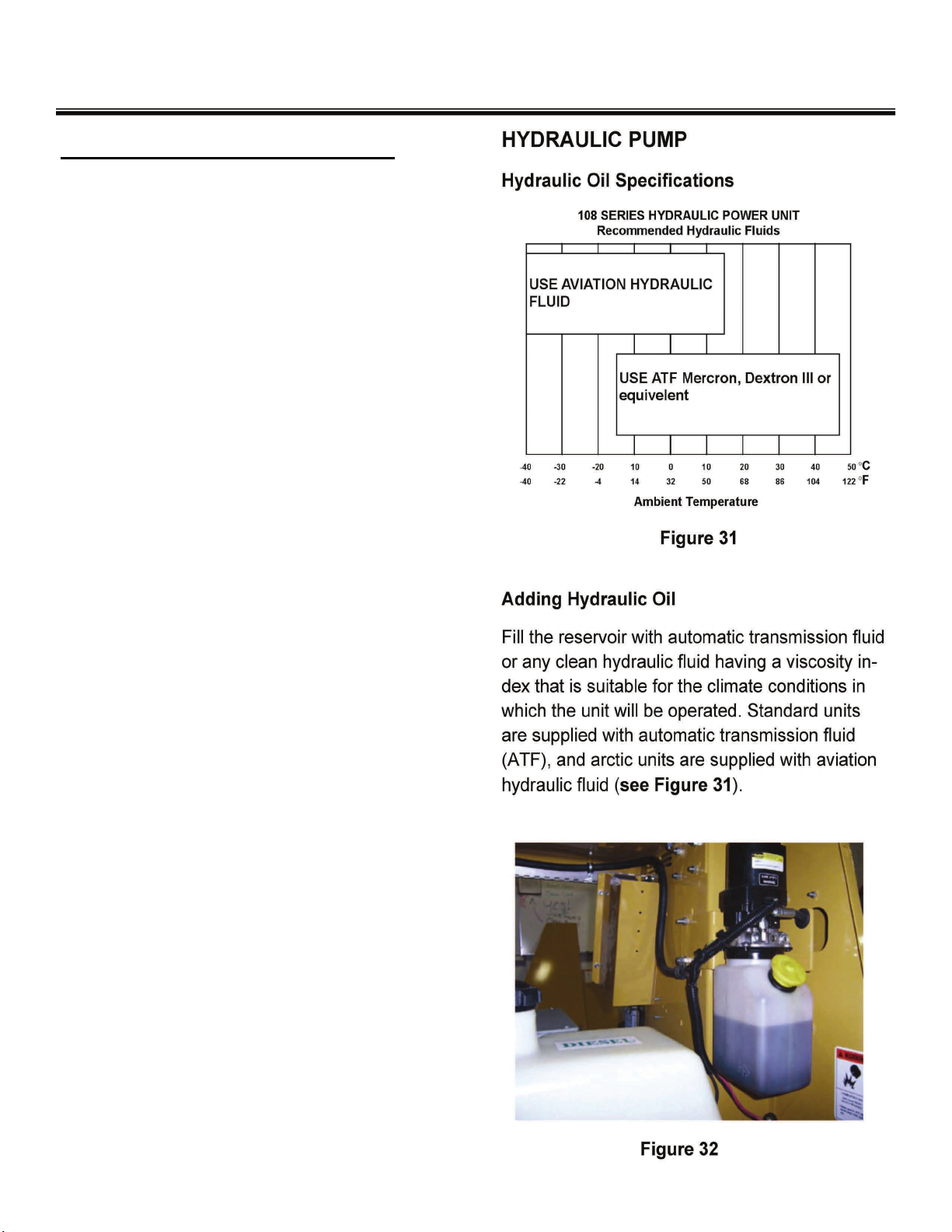
HYDRAULIC TOWER POWER UNIT
GENERAL START UP INSTRUCTIONS
NOTE: The ports are marked on the casing UP
and DN. When facing the power unit with the
motor up, plug the right hand, or DN port Jog
the motor until the oil flows from the left hand,
or up port. If oil does not flow from the UP port,
reverse the wire leads on the motor, and re-
peat. The pump is now primed. Connect the
hose (or tubing) to the UP port and tighten.
Connect the other hose end to the blind end of
a fully retracted hydraulic cylinder.
With the hose fitting loose, operate the power
unit until oil (and no air) bleeds from the fitting.
Tighten the fitting. Refill the reservoir.

10
10 11
TOWING INSTRUCTIONS
Before towing the MAXI-LITE the trailer should be inspected visually to insure that
the following operations have been completed.
1. Hitch is securely attached to towing vehicle (safety chains secure).
2. All outriggers and jacks are retracted and secured.
3. Tower is lowered.
4. Light xtures are positioned for transport.
5. Doors are closed and secure.
6. Check tires for adequate air
pressure
7. Taillights are connected and operating (if equipped).
8. Ground rod is removed from ground and secured in the trailer
GROUND ROD INSTRUCTIONS
1. Remove ground rod stowed just inside the left door (attached to the lower rame)
2. Unroll the electrical wire lead from the ground rod.
3. Attach the ground rod lead to the grounding lug located near the ballast compartment.
4. Drive the ground rod a minimum of 2 1/2 FT into the earth for adequate electrical grounding.
If this is not possible consult your local qualied electrician.
5. AFTER SHUTDOWN OF ENGINE: Remove the ground rod from the earth, remove lead from
the trailer ground lug and store ground rod inside left door.
TOWING AND STARTING INSTRUCTIONS
BEFORE STARTING:
1. Fill the engine with the right grade of lubricating oil (refer to the proper page of this manual or the Kubota,
CAT, or Lombardini diesel operators manual for oil specications)
2. Ensure there is an adequate supply of diesel fuel.
3. Ensure that the air cleaner is rmly attached and air cleaner seals and hose clamps are
properly sealed. Air cleaner element should be checked and replaced if necessary.
STARTING ENGINE
NOTE: The Kubota diesel engine includes a glow plug cold start system controlled by the yellow preheat but-
ton on the control panel. Glow plugs are not needed on a warm engine or if the ambient temperature is above
50 degrees F. The CAT C1.1 and Lombardini LDW 1003 diesel engines include a glow plug cold start
system controlled by the ignition switch on the control panel. Glow plugs are not needed on a warm engine or
if the ambient temperature is above 50 degrees F.
COLD WEATHER STARTING: KUBOTA (for temperatures below 32° F/ 0° C)
1. Turn the on-off switch to the ON position.
2. Press the yellow PREHEAT button for 5 seconds (10 seconds below 23° F maximum 20 seconds continu-
ous).
3. Press the green START button to crank engine until the engine starts.
4. If engine fails to start, it may be necessary to recycle the PREHEAT and Start steps #2 and #3 above

12
12
NOTE: Do not operate starter for more than 10 seconds without allowing 30 seconds to pass
between starting attempts. Possible starter damage could result from excessive heat caused by cranking
too long.
NOTE: If the engine develops sufcient speed to disengage the starter but does not keep
running (a false start), the engine rotation must be allowed to come to a complete stop
before attempting to restart the engine. If starter is engaged while the ywheel is rotating,
the starter pinion and ywheel ring gear may clash, resulting in damage to the starter or
ywheel ring gear.
NOTE:If the starter does not turn the engine over, stop cranking immediately. Do not make
further attempts to start the engine until the condition is corrected. See your local Kubota, CAT, or Lombar-
dini Engine Service Dealer for trouble analysis.
STARTING INSTRUCTIONS
COLD WEATHER STARTING: LOMBARDINI LDW 1003 (for temperatures below 32° F/ 0° C)
1. Turn the key switch to the PREHEAT position, hold until the glow plug indicator lamp goes out,
then release switch.
2. Turn the key switch to the START position and the engine should start. Release the key
immediately when the engine starts. If engine fails to start it may be necessary
to cycle the glow plugs again (see chart below)
COLD WEATHER STARTING CAT C1.1 (for temperatures below 32° F/ 0° C)
1. If the engine is cold, turn the key switch counterclockwise to the “preheat” position until the glow plug
indicator turns red. CAUTION: Never heat glow plugs more than 30 seconds or damage to the glow
plugs may occur.
2. Turn the key switch to the “start” position and start the engine immediately once the indicator turns red.
Release the key immediately when the engine starts. (If engine fails to start, repeat steps 1 and 2.)
FOR A WARM ENGINE (Kubota, CAT, and Lombardini engines)
Follow the same procedure as described for cold weather starting, skipping step 1 (step 2 for Kubota).
Use of the glow plugs is not recommended when engine is warm.
LOW OIL PRESSURE SHUT-OFF SYSTEM
Should a low oil pressure condition occur, the oil pressure sending unit breaks the circuit between the
battery and the fuel solenoid, allowing the spring load to immediately move the fuel control to the shut-off
position.
HIGH COOLANT TEMPERATURE SHUT-OFF SYSTEM
Should a high coolant temperature condition occur, the temperature sending unit breaks the circuit be-
tween the battery and the fuel solenoid, allowing the spring load to immediately move the fuel control to
the shut-off position.
STOPPING THE ENGINE
To stop the engine turn the ignition switch to the off position, this breaks the circuit between the battery
and the fuel solenoid, allowing the spring load to immediately move the control to the shut-off position
12
12 13
SERIAL NUMBER LOCATIONS
SERIAL NUMBER LOCATION
Trailer: All MAXI-LITE models have a serial num-
ber plate located on the lower left side of the rear
panel.
SERIAL NUMBER LOCATION
Generator: The generator has a plate at-
tached to the side of the housing.
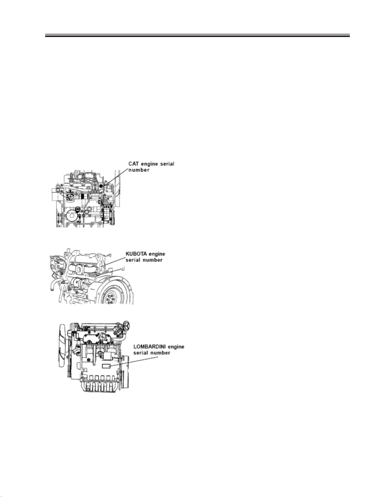
Engine: CAT engines have the serial num-
ber stamped on the right side of the engine
block just ahead of the rst cylinder. (see
illustration)
KUBOTA engines have the serial number
stamped on the engine block just below the
exhaust manifold. (see illustration)
LOMBARDINI engines have the serial num-
ber tag located on the right side of the en-
gine block. (see illustration)

14
14
MAXI-LITE DIMENSIONS
Height lowered: 6’6” (1.98 m)
Height extended: 30’ (9.14 m)
Length: 14’9” (4.49 m)
Width: 6’4”(1.92 m)
Outrigger width: 11’6”(3.5 m)
Trailer: Structural steel frame
Leaf spring axle
Wheels & tires: 15”
DOMESTIC SHIPPING WEIGHT
Fixtures: 15 Ibs. ea. = 60 Ibs.
Total weight: 2,580 Ibs. (963 kg)
SPECIFICATIONS
TRAILER
The engine-generator set is housed in a lockable enclosure with the frame fabricated
from heavy gauge steel mounted on a two-wheel leaf spring axle. The design enables
the trailer to contain the outriggers in a simple compact position. The design includes
an adjustable-height reversible hitch that includes a 2” ball and a 3” pintle hook hitch.
MAST
When the mast is in the operating position it is located in the middle of a three point
outrigger system for optimum balance and stability.
The mast consists of seven fabricated steel sections that telescope to 25 ft and UHMW
plastic guide pads to provide smooth operation and reduced friction.
The mast sections are extended with either a manual or electric winch, or hydaulic
pump. The electric winch design includes limit switches that turn the winch off when the
mast reaches full extension or is fully retracted.
STABILIZERS
Four (4) point outrigger design with tower center mounted between two (2) retractable
side outriggers, tongue jack and rear jack.
FLOOD LIGHT ASSEMBLY
The ood light assembly consists of four 1250 watt lamp xtures sealed for all weather
use.
SHO 1250 xture - Metal Halide Lamp
Lumen rating: 150,000 initial lumens
Warm up time: 2-4 minutes
Restart time: 10-15 minutes

14
14 15
SPECIFICATIONS
Low oil pressure and high engine temperature shut-downs are standard equipment.
Both The Kubota, CAT, and Lombardini diesel are equipped with glow plug cold start as-
sist as standard equipment.
NOTE: See the appropriate section of this manual for cold weather starting instructions
or consult the Operators Manual for your particular engine application.
Horsepower ratings are established in accordance with Society of Automotive Engineers
Small Engine Test Code- J1349 GROSS.

16
16
GENERATOR
7.5 kw and 8 kw models available
60 hz and 50 hz models available
FUEL REQUIREMENTS
Use a clean No. 2 Diesel fuel oil (SAE J313 JUN87) according to ASTM D975. Do not
use alternative fuel, because its quality is unknown or it may be inferior in quality,and
kerosene, which is very low in cetane rating, adversely effects the engine. Refer to the
Kubota, CAT, or Isuzu Operators Manual for more detailed fuel requirements.
KUBOTA LUBRICATION CHART
CAT LUBRICATION CHART
LOMBARDINI LUBRICATION CHART
SPECIFICATIONS

16
16 17
CONTROLS AND COMPONENTS
NOTE: COMPONENTS SHOWN ARE STANDARD. PICTURES MAY VARY WITH DIFFERENT OPTIONS.
FIG. 1. AC CONTROL PANEL
FAILURE TO UNDERSTAND AND COMPLY
WITH SAFETY RELATED INFORMATION
AND INSTRUCTIONS MAY RESULT IN
INJURY TO THE OPERATOR OR OTHERS.
IF YOU DO NOT UNDERSTAND ANY PART
OF THIS CONTACT YOUR DEALER FOR
CLARIFICATION PRIOR TO OPERATING
EQUIPMENT.
SAFETY WARNING
FIGURE 1 FIGURE 2
1. Switch, Circuit Breaker (Lights 1 through 4)
2. Switch, Circuit Breaker (240V Receptacle)
3. Switch, Circuit Breaker (120\/ Receptacles)
FIG. 2. DC CONTROL PANEL
4. Voltmeter (optional)
Indicates charging circuit voltage
5. Hour Meter
Shows total elapsed hours of engine operation.
6. Momentary Contact Switch. Lift up to raise and
extend the tower.
Press down to Iower the tower.
7. Ignition Switch
8. Glow plug indicator
release Ignition switch when indicator begins
glowing.
9. 2 AMP Circuit Breaker (Hydraulic Pump)
1
23
4
5
6
9
8
7

18
18
CONTROLS AND COMPONENTS
NOTE: COMPONENTS SHOWN ARE STANDARD. PICTURES MAY VARY WITH DIFFERENT OPTIONS.
FIG. 3 BALLAST PANEL
11. Ballast, Capacitors 1 through 4
12. Ballast, Transformers 1 through 4
FIG. 4 CONVENIENCE PANEL
13. 120 Volt/ 15 Amp Outlet Receptacles
(Ground fault)
14. 240 Volt/ 15 Amp D.C. Outlet Recep-
tacle
FAILURE TO UNDERSTAND AND COMPLY
WITH SAFETY RELATED INFORMATION
AND INSTRUCTIONS MAY RESULT IN
INJURY TO THE OPERATOR OR OTHERS.
IF YOU DO NOT UNDERSTAND ANY PART
OF THIS CONTACT YOUR DEALER FOR
CLARIFICATION PRIOR TO OPERATING
EQUIPMENT
SAFETY WARNING
18
18 19
CONTROLS AND COMPONENTS
NOTE: COMPONENTS SHOWN ARE STANDARD. PICTURES MAY VARY WITH DIFFERENT OPTIONS.
FIG. 5 GROUND ROD
16. Ground Rod
Ground Rod should be attached
to grounding lug with wire pro-
vided and ground rod and then
driven fully into the eqrth for
adequate electrical ground as
required by local, state or na-
tional electrical codes.
16
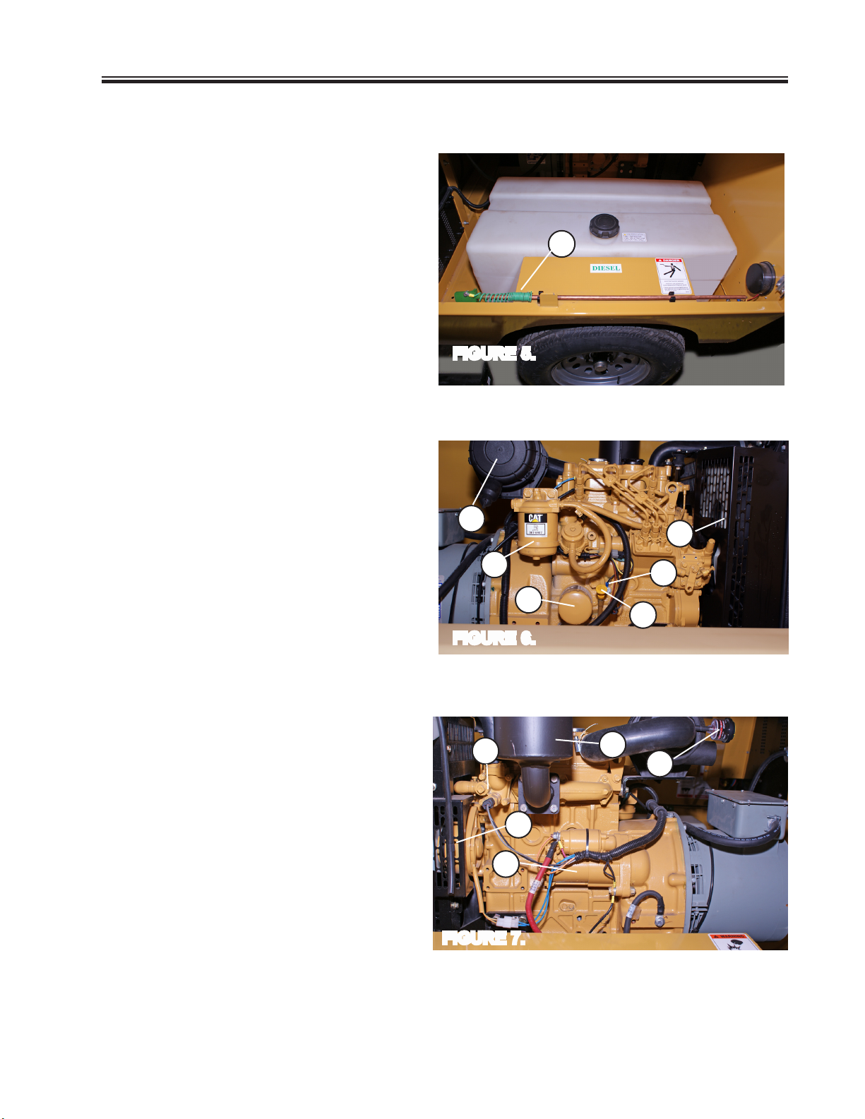
FIG. 6 ENGINE (Left Side)
17. Air Cleaner
18. Fuel Filter
19. Oil Filter
20. Radiator
21. Oil Dipstick
22. Oil Pressure Sensor
FIG. 7 ENGINE (Right Side)
23. Starter
24 Alternator
25. Mufer
26. Air Cleaner Service Indicator
27. Coolant Temperature Sensor
18
17
19 21
20
23
24
25
26
FIGURE 5.
FIGURE 6.
FIGURE 7.
NOTE: Above photos illustrate component locations on the CAT C1.1 diesel engine. Com-
ponent location on other engine models may vary from the locations indicated above.
22
27

20
20
CONTROLS AND COMPONENTS
NOTE: COMPONENTS SHOWN ARE STANDARD. PICTURES MAY VARY WITH DIFFERENT OPTIONS.
FIG. 8 REAR JACK
28. Rear Jack
FIG. 9 OUTRIGGER JACK
29. Pin--Retains outrigger in retracted
position for towing.
30. Jack Pin--Pull to allow jack to
rotate
31. Outrigger Jack
32. Jack Handle--Crank handle to
raise and lower foot of jack to
level trailer.
28
29
30
31
32
FIGURE 8.
FIGURE 9.
Other manuals for MAXI-LITE V Series
1
Table of contents
Other Allmand Industrial Equipment manuals


