Allmatic Blanc 800 User manual

BLANC
800
6-1622415 REV. 1
OPERATOR 24Vdc
FOR SECTIONAL AND
GARAGE DOORS


46-1622415 rev.1 01/10/2019
Contents
Contents
About this manual .................................................................................................................................................... 5
Contents and intended audience .......................................................................................................................... 5
Language............................................................................................................................................................... 5
Symbols used in this manual ................................................................................................................................ 5
Use according to purpose ....................................................................................................................................... 5
Safety......................................................................................................................................................................... 6
General safety precautions ................................................................................................................................... 6
Specic safety precautions................................................................................................................................... 6
Product description.................................................................................................................................................. 7
General product overview ..................................................................................................................................... 7
Control elements ................................................................................................................................................... 7
Functioning of integrated safety unit..................................................................................................................... 8
Installation................................................................................................................................................................. 8
Safety instructions for installation ......................................................................................................................... 8
Scope of delivery................................................................................................................................................... 9
Prepare the site for installation............................................................................................................................ 10
Mount the garage door operator......................................................................................................................... 10
Connect the garage door operator to electrical power and controls.................................................................. 11
External antenna ................................................................................................................................................ 12
External pulse generator (accessories connection) ........................................................................................... 12
Photocells connection ........................................................................................................................................ 12
Routing the antenna ........................................................................................................................................... 15
Program the drive head....................................................................................................................................... 16
Special settings................................................................................................................................................... 18
Complete the installation procedure ................................................................................................................... 22
Operation ................................................................................................................................................................ 23
Safety instructions for operation ......................................................................................................................... 23
Open or close the garage door (in normal operation mode) ............................................................................... 23
Manually open or close the garage door ............................................................................................................ 24
Open or close the garage door (other operation modes).................................................................................... 24
Diagnostic display .................................................................................................................................................. 25
Restore the factory settings ................................................................................................................................ 26
Cycle counter ...................................................................................................................................................... 26
Technical data......................................................................................................................................................... 27
Inspection and test log book for the door system .............................................................................................. 28
Testing the garage door drive ............................................................................................................................... 28
Check list for the garage door operator .............................................................................................................. 29
Maintenance/ checks............................................................................................................................................ 30
Cleaning / Care....................................................................................................................................................... 30
Declaration of conformity and incorporation ...................................................................................................... 31
Declaration of Incorporation in accordance with the EC Machinery Directive 2006/42/EC ............................... 31
EN

5
About this manual
6-1622415 rev.1 01/10/2019
About this manual
Contents and intended audience
This manual gives information about the Blanc 800 series garage door operator (hereinafter referred to as ‘the
product’). The manual is intended for technicians that install and maintain the product, and for consumers that use
the product on a daily base.
Language
This manual was prepared in German. Any other language version is a translation of this original.
Symbols used in this manual
Warning:
This indicates a possibly dangerous situation that might lead to serious injury.
Warning high voltage:
This indicates work steps that may be carried out only by a trained and skilled electrician.
!Caution:
This indicates a possibly dangerous situation that might lead to material damage to the product.
Use according to purpose
The product is designed exclusively for opening and closing spring or weight-balanced garage doors. It may not
be used for garage doors without spring or weight-balancing mechanisms.
See CE declaration.

66-1622415 rev.1 01/10/2019
Safety
Safety
General safety precautions
Warning!
Make sure that you read this manual and that you understand its contents before you start working
with the product.
Warning!
Keep this manual with the product for future reference.
1. Obey the instructions in this manual. Incorrect installation or incorrect use can cause serious injury or damage
to the product.
2. Any damage or injury as a result of not following the instructions in this manual will render the manufacturer’s
liability null and void.
3. Only use the product for the intended use as mentioned in this manual.
See CE declaration.
4. Please also see the safety instructions for operation (see “Operation” on page 23).
5. Installation must only be carried out about by qualied technicians.
Specific safety precautions
6. The product runs on high voltage. Before you start work on electrical systems, do the following:
1. Make sure that the product is disconnected from the electrical power supply.
2. Make sure that the power cannot be reconnected unintendedly during work on the electrical system.
7. Never make any modications or changes to the product that have not been expressly approved by the
manufacturer.
8. The design and execution of the product based on this corresponds to state-of-theart technology.
9. Only use genuine spare parts of the manufacturer. Wrong or faulty spare parts can cause damage,malfunctions
or even a total failure of the product.

7
Product description
6-1622415 rev.1 01/10/2019
Product description
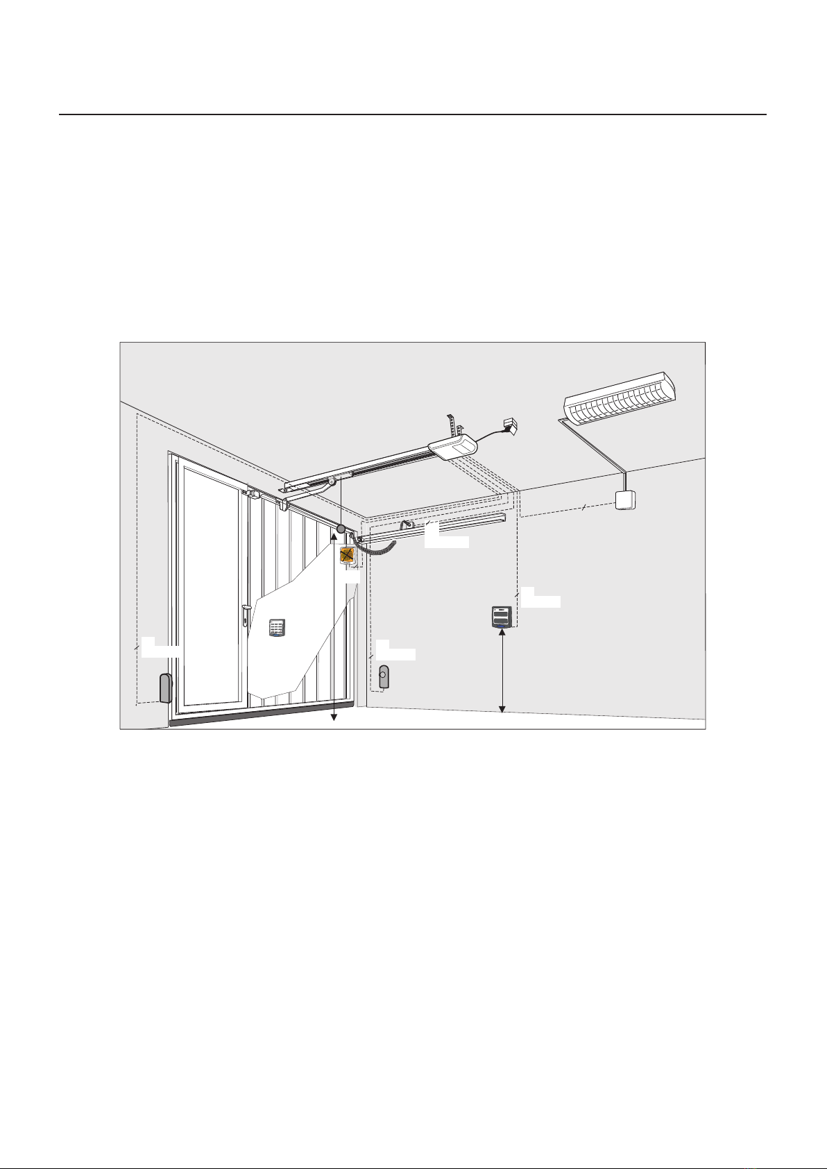
General product overview
10
9
12
20
3
7
16
1
16
8
13 11
17
4
*
* Example garage door illustration
1. Drive head including LED module 11. Door connector attachment
3. Rail (model example) drive side 12. Linking bar
4. Carriage 13. Central support
7. Rail connector (model example) 16. Support straps drive head
8. Rail (model example) door side 16. Support straps track
9. Tensioner 17. Mains cable, 1.2 m
10. Wall bracket 20. Telescopic tting for sectional doors (accessory)
Control elements
A
C
B
A1
D
15
1
A. Numerical display (A1 digital point)
C. OPEN / Start button
B. CLOSE button
D. Program button (PROG button)
1. Drive head
15.Hand transmitter TECH3 PLUS
86-1622415 rev.1 01/10/2019
Installation
Functioning of integrated safety unit
If the closing garage door encounters an obstruction, the closing motion stops and the door opens a few
centimetres again, or, depending on its position, completely.
If the opening garage door encounters an obstruction, the door stops and moves back for approximately
1 second.
Installation
Drive and accessories
2x
AWG 22
Y-OB
2 x 1,0
2 x
2x
AWG 22
2x
AWG 22
2x
AWG 22
mm0051
mm0081.xam
Safety instructions for installation
• Installation must only be carried out about by qualied technicians.
• Read these installation instructions before you start installing the product.

9
Installation
6-1622415 rev.1 01/10/2019
Scope of delivery
The scope of delivery depends on your product conguration. It generally comprises the following:
1
10
11
18
16
13
8
3
5
17
15
1x
12 1x
14 1x
1x
4x
2x
1x
19 1x
1x 1x
1x
7
2
9
6
4
WARNUNG: Automatisches Tor - Nicht im Bewegungsbereich des
Tores aufhalten, da sich das Tor unerwartet in Bewegung setzen kann!
WARNING: Automatic door - The door may operate unexpectedly,
therefore do not allow anything/anyone to stay in the path of the door!
Automatic Door
1. Drive head including LED module
2. Pinion*
3. Rail (model example) drive side*
4. Carriage*
5. Toothed belt or chain*
6. Deection roller*
7. Rail connector (model example)*
8. Rail (model example) door side*
9. Tensioner*
10. Wall bracket*
11. Door connector attachment
12. Linking bar
13. Central support
14. Bag of screws
15. Handheld transmitter (TECH3 PLUS)*
16. Ceiling mounting
17. Mains cable, 1.2 m length
18. Mounting bracket
19. Warning label
*Optional
Attention: Check the supplied screws and wall plugs to make sure that they are suitable for the structural
condition on the installation site.
10 6-1622415 rev.1 01/10/2019
Installation
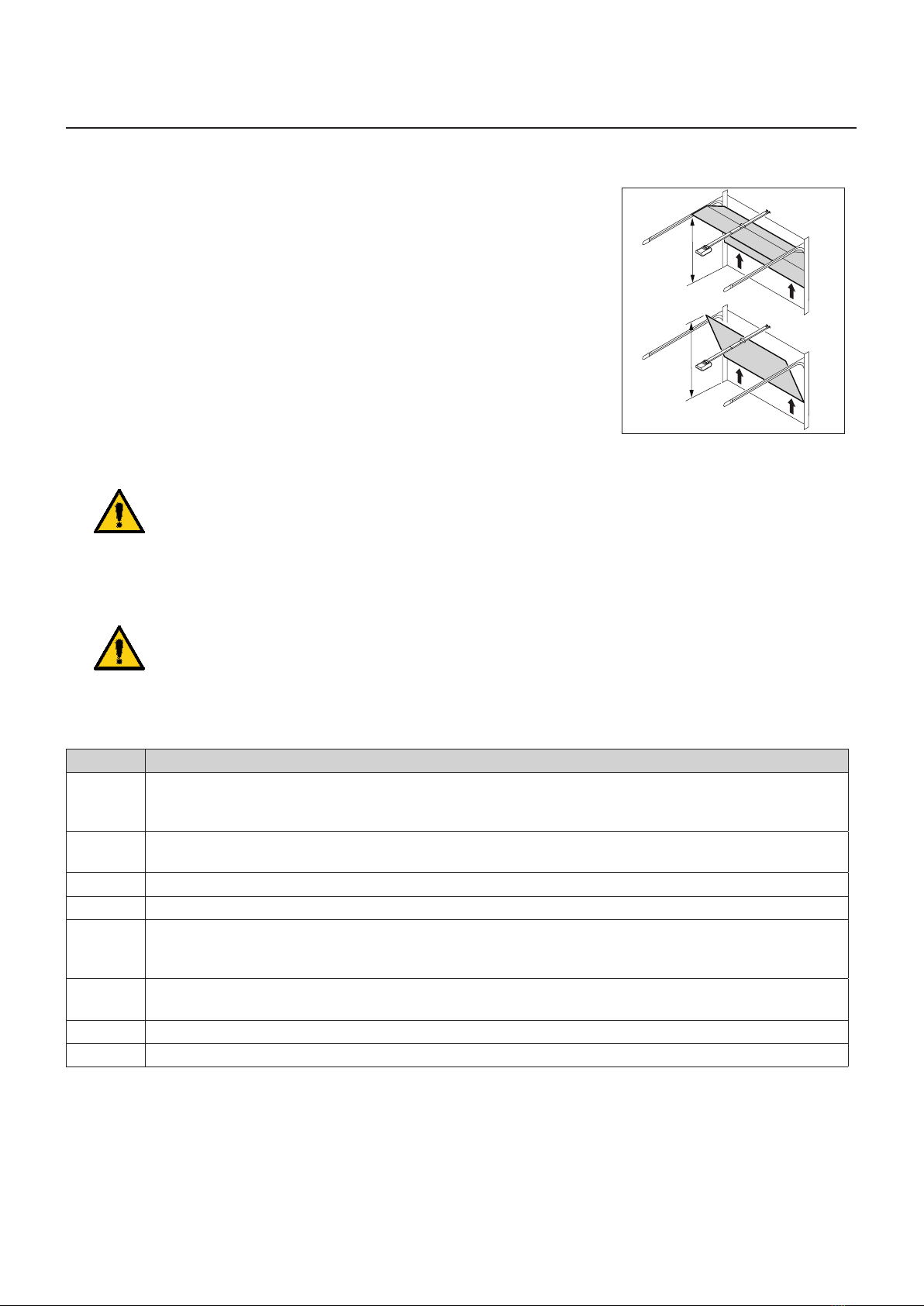
Prepare the site for installation
1. The maximal distance between the drive head and wall socket is 1.2m.
2. Check the stability of the garage door. If necessary, tighten the screws and
nuts of the garage door.
3. Make sure that the garage door runs smoothly.
- Lubricate shafts and bearings.
- Check the pretension of the springs and adjust if necessary.
4. Establish the clearance at opening and closing of the garage door (h).
h
h
5. Close the garage door and disable any existing locks. Dismantle the locks if necessary.
Warning:
Some parts of the latching devices on the existing garage door can form pinch or shear points.
If necessary, remove hazardous parts before installation.
6. For garages without a second entrance, an emergency release is required (accessory).
7. If the garage door is a wicket/pass door, install the wicket door contact rst.
Warning:
Do not allow parts of the gate to enter public footpaths or roads.
Mount the garage door operator
Follow instructions as shown in the A3 Instruction poster.
Step Installation
1 Fold out the track to its full length (3&8).
Push the track connector (7) centrally over the joints. The chain or the toothed belt may have to be
re-stressed. See illustration.
2 Mount the center suspension (13) to the guide rail.
Mount the mounting brackets (18) on the drive head (1).
3 Mount the connector attachment (11) to the garage door.
4 Mount the wall bracket (10).
5a
5c/d
Mount the guide rail (3&8) to the wall bracket (10).
Mount the ceiling mountings (16) to the center bracket (13) and to the drive head (1).
Then, mount the ceiling mountings (16) to the ceiling.
6 Connect the linking bar (12) between the carriage (4) and the garage door connector
attachment (11).
7 For programming, open the cover of the drive head with a screwdriver or a similar tool.
8 Attach the warning sticker (19) to the inside of the garage door so that it is easily visible.
11
Installation
6-1622415 rev.1 01/10/2019
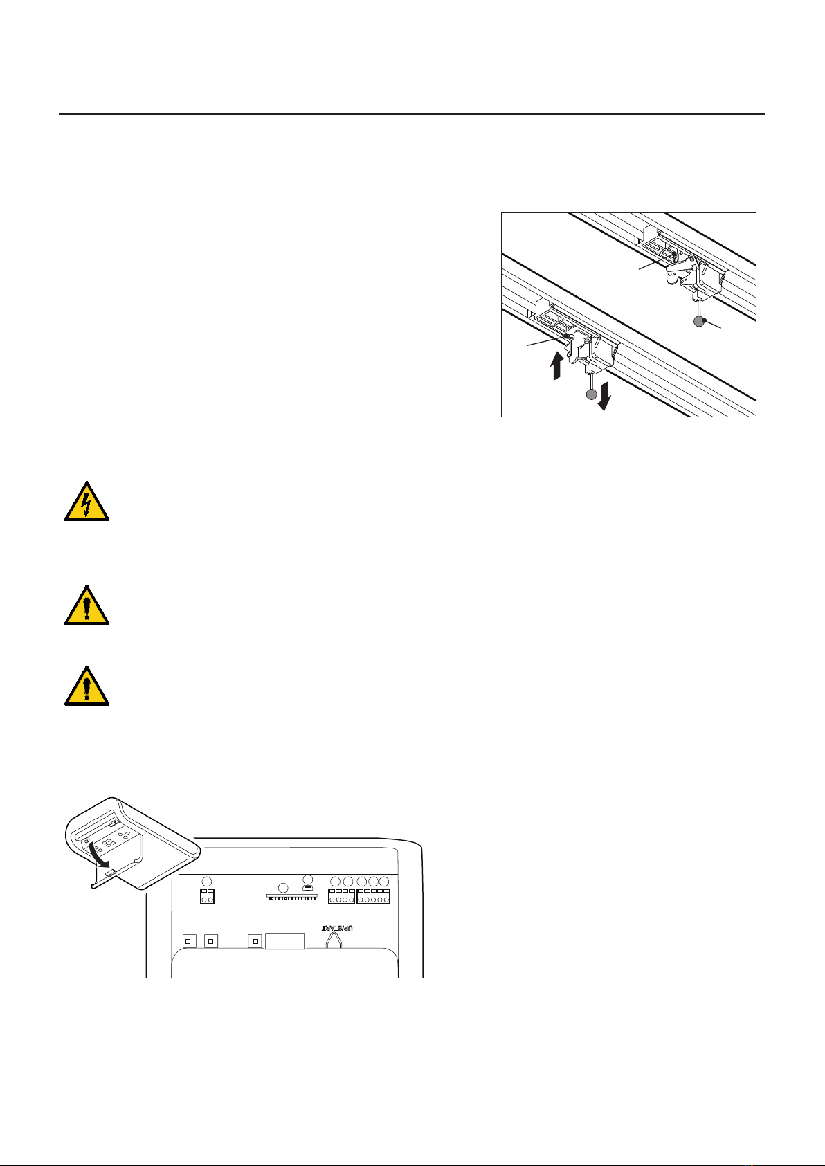
Disengage the carriage
During the proceeding work, it may be necessary to disengage the carriage from the connector attachment.
This can be done without the need to disconnect the linking bar.
1. To move the garage door, manually pull on the pull cord (I) on the
carriage.
2. Disconnect the carriage from the toothed belt or the chain.
3. The garage door can now be moved manually.
4. To operate the gate manually for a longer period of time, you can
insert the locking pin (II) into the carriage (III) in the bore provided
for this purpose. To restore normal operation, loosen the locking
pin (II).
II
III
I
Connect the garage door operator to electrical power and controls
Warning high voltage:
• Pull out the main plug from the mains socket before you open the cover of the drive head.
• Do not connect any live leads. Only connect potential-free buttons and potential-free relay
outputs.
• After connecting all cables, connect the cover to the drive head again.
Warning:
Before using the operator for the rst time, it must be tested to make sure that it is working properly
and safely (see section on Maintenance/Checks).
Warning:
Danger by optical radiation!
If you look at an LED for an extended period from a short distance, this can cause optical binding.
Sight is then severely restricted for a short time. This can result in serious or fatal injuries.
You must not look directly at an LED.
I
KH G F E
P
J

12 6-1622415 rev.1 01/10/2019
Installation
1. External antenna
Lead the antenna upward through the housing recess.
When using an external antenna, the shield must be placed on the right
adjacent terminal (F).
E - Connector for antenna
8k2
2. External pulse generator
F -Connector for external impulse generator (accessories, e.g.
keyswitch or code keypad)
8k2
3. Input STOP-A
The drive is stopped or the start-up is suppressed via this input.
G - Connection for slip contact (accessory) or emergency stop.
Please also observe “Menu H:
STOP-A settings” on page 22.
4. Input STOP-B
This input activates the automatic reversal of the drive during closing.
H - Connection 4-wire photoelectric sensor
- +-+
8k2
Rx Tx

13
Installation
6-1622415 rev.1 01/10/2019
Input STOP-B
G // H - Connection of 2-wire photocell
2-wire photocell IRIS PULS 2-wire photocell IRIS PULS BAT (wireless transmitter
with batteries inside)
+
-
1 2
+
-
1 2
Rx
IRIS PULS
Tx
IRIS PULS
8k2
+
-
1 2
Rx
IRIS PULS
BAT
ON
N.C.
EDGE
1 2
Tx
IRIS PULS
BAT
8k2
Warning!
Following the connection of 2-wire pulsed photocells (IRIS PULS or IRIS PULS BAT) it is necessary to
repeat the learning sequence of learning of the end positions, including the force learning cycle
5. Power supply 24 V DC, max. 100 mA (switched)
I - Connection for e.g. 24 V signal light (accessory)
8k2
6. Power supply 24 V DC, max. 100 mA (permanent)
I - Connection for e.g. external receiver (accessory)
8k2

14 6-1622415 rev.1 01/10/2019
Installation
7. Lighting
K - Connection for external, protectively insulated lighting or signaling
lamp (protection class II, max 500 W) (accessory)
ATTENTION!
Connect ashing lamp type B.RO LIGHT 230Vac with ashing circuit.
Caution!
Do not connect a push button.
K
230V
Pulse generator and external safety devices
In situations of increased requirements in terms of personal protection, we recommend, in addition to
the internal power limitation of the drive, the installation of a 2-wire photoelectric sensor.
The installation of a 4-wire photoelectric sensor serves purely for the protection of property.
For further information on our range of accessories, please refer to our sales literature or consult your
specialist dealer.
Warning label
WARNUNG: Automatisches Tor - Nicht im Bewegungsbereich des
Tores aufhalten, da sich dasTor unerwartet in Bewegung setzen kann!
WARNING: Automatic door - The door may operate unexpectedly,
therefore do not allow anything/anyone to stay in the path of the door!
Automatic Door
Place the sticker clearly visible on the inner surface of the garage door.
Dismantling the operator
1. Pull out the mains plug and disconnect all existing terminals.
2. Disconnect garage door and operator. Fix garage door.
3. Proceed according to the Installation instruction poster, but in reverse sequence.

15
Installation
6-1622415 rev.1 01/10/2019
Routing the antenna
Hazardous voltage!
• Pull out the main plug from the mains socket before you open the cover of the drive head.
• Having installed the antenna, connect the cover to the drive head again.
1. Open the cover at the drive head.
PJ
IK
H
G
FE
2. Use a suitable tool (e.g. a screwdriver) to break out the
material at the predetermined breaking point for the
feed-through and insert the supplied cable sleeve into
the resulting opening. PJ
IK
H
G
FE
3. Take the antenna out of the transport lock and feed it
outwards through the feed-through.
PJ
IK
H
G
FE
4. Close the cover at the drive head.
Note:
When using an external antenna, the shield must be placed on the right adjacent terminal(F).
16 6-1622415 rev.1 01/10/2019
Installation
Program the drive head
This section describes the normal programming of the drive head during installation.
For further adjustments, or for special adjustments, refer to the section ‘Special settings’.
Preparation
1. Make sure that the garage door is securely engaged in the carriage.
2. Make sure that the aerial is correctly positioned.
3. Make sure that you have all hand transmitters for this garage door at hand.
4. Open the cover of the drive head with a screwdriver.
5. Connect the mains plug to the mains socket. The point display lights up.
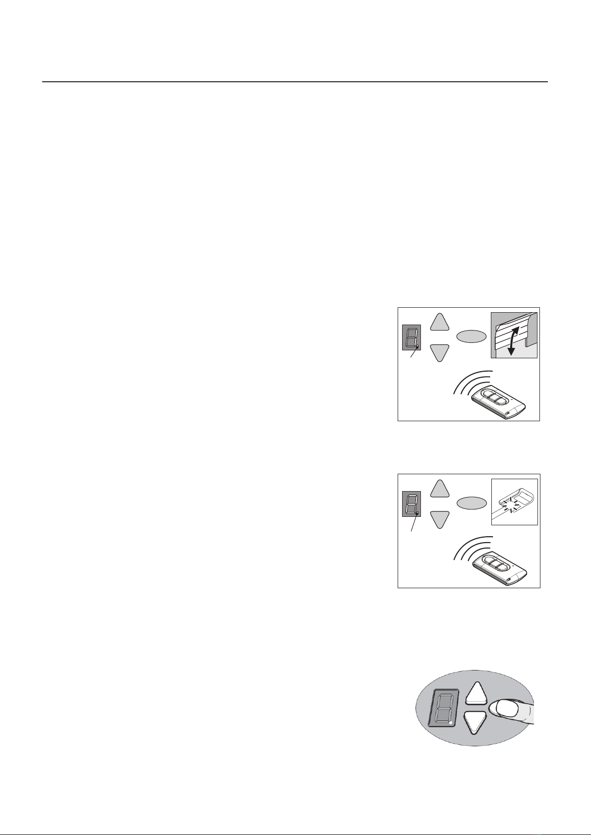
Menu 1:
Program the start signal of the hand transmitter
1. Briey press the programming button (PROG button) (D).
The display shows “1”.
2. When the display ashes, press the hand transmitter button with which
you will later start the drive until the digital point (A1) on the display blinks
4 times.
3. As soon as the light goes out, you can set the next hand transmitter
(see Step 1).
Note: Up to 30 codes can be learned.
D
C
B
A1
Menu 2:
Programming the 4-minute light
1. Briey press the programming button (PROG button) (D) twice.
The display shows “2”.
2. Press the button on the hand-held transmitter to control the light until the
digital point (A1) ashes 4x.
3. As soon as the light goes out, you can set the next hand transmitter
(see Step 1).
Note: Programming the ventilation position and partial opening:
see menu 9.
Note: Up to 30 codes can be learned.
(Example 15x start 15x light).
Delete all radio codes
1. Pull the main plug
2. Push and hold the oval PROG-Button (D).
3. Connect the mains plug to the mains socket and keep the PROG button
(D) pressed until the digital point ashes quickly.
D
C
B
A1

17
Installation
6-1622415 rev.1 01/10/2019
Menu 3 + Menu 4:
Setting the end positions
1. Keep the programming button (PROG button) (D) pressed in for
approximately 3 seconds. The display shows “3”.
2. Press the OPEN button (B) and check if the garage door moves to the
OPEN position.
3. If the garage door moves in the wrong direction, keep the programming
button (PROG button) (D) pressed in for approximately 5 seconds until a
chaser light appears.
4. Keep the OPEN button pressed until the garage door is at the desired
end position OPEN. If needed, press the CLOSE button (C) to adjust the
position.
5. Once the garage door is at the desired OPEN position, press the
programming button (PROG button) (D). The display shows “4”.
B
C
D
6. Press the CLOSE button (C) as soon as the display ashes.
7. Keep the CLOSE button pressed until the garage door is at the desired
end position CLOSE. If needed, press the OPEN button (A) to adjust the
position.
8. Once the garage door is at the desired end position CLOSE, press the
programming button (PROG button) (D). The display shows “0”.
9. Continue with the force learning cycle.
B
C
D
Force learning cycle
Warning:
During this procedure, the operator automatically learns the normal mechanical force required to
open and close the garage door. Force limits are deactivated until the conclusion of the learning
cycle. Keep a sufcient distance from the entire path of motion of the garage door!
Do not interrupt this procedure.
Note:
During this procedure the display shows a “0”.
1. Press the OPEN button (B) or use the set hand transmitter. The garage
door moves from the end position CLOSE and moves to the end position
OPEN.
2. Press the OPEN button (B) again or use the set hand transmitter. The
garage door moves from the end position OPEN to the end position
CLOSE.
After about 2 seconds, the ‘0’ on the display goes out.
Note: After completing the force learning cycle, the display ‘0’ must go out.
B
C
D

18 6-1622415 rev.1 01/10/2019
Installation
Checking force limit
1. Place an force gauge or obstruction (e.g. the operator’s cardboard box) in
the closing area of the door.
2. Close the garage door. The garage door moves to the end position
CLOSE. When the garage door reaches the obstruction, the garage door
must stop and then move back to the end position OPEN.
3. If the door can lift persons (e.g. openings greater than 50 mm or treads),
the force limiting unit must be checked in the opening direction: For
additional load of the door with 20 kg of mass, the drive has to stop.
Check and document the force limits every month.
Note:
If the obstruction is not detected or if the force values are not complied with, the force limit needs to be set
according to the section “Menu 5 + Menu 6:
Force limitation for Open and Close” on page 19.
Delete force learning cycle
Note: The force learning cycle always starts from the end position CLOSE.
The force learning cycle must be repeated after each replacement of the
garage door springs:
Proceed to Menu 5 (see special settings) and keep the programming button
(PROG button) (D) pressed for 3 seconds. The display shows “0”.
Complete the process as described in the section ”Force learning cycle” on
page 17.
Special settings
Open the special settings menu
1. Keep the programming button (PROG button) (D) pressed in for approximately 3 seconds.
The display shows “3”.
2. Press the programming button (PROG button) (D) again. The display shows “4”.
3. Keep the programming button (PROG button) (D) pressed in again for approximately 3 seconds.
The display shows “5”.

19
Installation
6-1622415 rev.1 01/10/2019
Menu 5 + Menu 6:
Force limitation for Open and Close
Warning:
If the setting is too high, persons may be placed at risk of injury.
In the delivery state, the set value is ‘6’ when opening and ‘4’ when closing. We recommend selecting
the appropriate door type in menu 8 before the force learning cycle.
1. Select menu item “5”.
After about 2 seconds, the display blinks and the set value of the power limit for upward motion appears.
2. If desired, adjust the setting with the aid of the OPEN (B) and CLOSE (C) buttons.
3. Press the programming button (PROG button) (D).
The display shows “6”. After about 2 seconds the display and the set value for the power limit for closure
appears.
4. If desired, adjust the setting with the aid of the OPEN (B) and CLOSE (C) buttons.
Warning:
The force on the main closure side must not exceed 400 N / 750 ms!
5. Press the programming button (PROG button) (D).
The display shows “7”.
Menu 7:
Adjust the light phases
1. Select menu item “7”.
After about 2 seconds the display blinks and the set value for light time appears.
The factory setting is "0”.
2. If desired, adjust the setting with the aid of the OPEN (B) and CLOSE (C) buttons.
Menu value Light time Warning time 24 V
0 60 s 0 s 60 s
1 120 s 0 s 120 s
2 240 s 0 s 240 s
3 0 s 0 s 0 s
4 0 s 3 s 0 s
5 60 s 3 s 0 s
6 120 s 3 s 0 s
7 60 s 0 s TAM
8 120 s 0 s TAM
9 240 s 0 s TAM
Remarks:
- TAM (Door open message): 24 volts at door not closed.
- With set warning time light and 24V for drive of control goes on.
3. Press the programming button (PROG button) (D).
The display shows “8”.

20 6-1622415 rev.1 01/10/2019
Installation
Menu 8:
Door adjustments
1. Select menu item “8”.
After about 2 seconds the display blinks and the set value time appears.
At delivery, the factory setting is ‘4’.
For optimal movement and to maintain the forces, the corresponding door type must be selected.
2. If desired, adjust the setting with the aid of the OPEN (B) and CLOSE (C) buttons.
Menu value Door type
0 Double swing gate
1 Non-swinging door, Canopy
2 Swing door, Kipptor normal
3 Swing door, tilt sensitive running
4 Universal setting (factory)
5 Sectional door with tension spring tting (Topspeed)
6 Sectional door with torsion spring tting (Topspeed)
7 Industrial door with standard ttings
8 Side section door (Topspeed)
9 Side section door with secondary closing edge
3. Press the SAVE button (D).
The display shows “9”.
Table of contents
Other Allmatic Garage Door Opener manuals


Popular Garage Door Opener manuals by other brands


Nice
Nice Spido Instructions and warnings for the fitter

Raynor
Raynor FliteStar-7 installation instructions

Chamberlain
Chamberlain LiftMaster Professional Security+ 3575C owner's manual

CAME
CAME 119BW41EN installation manual

Nice
Nice FILO Series Instructions and warnings for installation and use

Chamberlain
Chamberlain C610C owner's manual


