AllScanner VXDIAG VCX-DoIP User manual

19
General information
Please carefully check the instructions for use of the product and operate the product in strict
accordance with the instructions for use.
Welcome to our website.
Thank you for choosing the diagnostic products of Shenzhen Allscanner Technology Co., Ltd. This manual
is the user manual of automobile diagnostic equipment and is provided to the user together with the
products.
This manual describes important information such as product information, hardware connection,
software installation and operation method. Please read this manual carefully before using the product
for the first time. This manual only describes the operation and use of the product. Please refer to the
maintenance manual of the original vehicle for specific vehicle maintenance and diagnosis.
Due to the product update, Shenzhen Allscanner Technology Co., Ltd. reserves the right to change the
contents of this manual without prior notice to users.
limited liability
OSCARL does not warrant that the use of this product will be uninterrupted or error free. In no event shall
OSCAR be liable for any direct, indirect, special, incidental or consequential damages (including lost
profits), whether based on warranty, contract, tort or any other theory of law.
All rights reserved.
All contents of this manual are copyrighted by Shenzhen Allscanner Technology Co., Ltd. Without
permission, any individual or company shall not copy, backup or reissue the contents of this manual in
any form for the purpose of commercial interests!
registered trademark
Is a registered trademark of Shenzhen Allscanner Technology Co., Ltd.
Is a registered trademark of Shenzhen Allscannerl Technology Co., Ltd.
Except as stated above, all other trademarks mentioned in this manual belong to their registered
companies.

20
Product Introduction
Product Overview
VCX-DoIP is the latest generation of vehicle network interface equipped with DoIP Ethernet diagnostic
technology, integrating four automobile industry standards into one device, not only supporting all
traditional vehicle bus protocols, but also supporting the latest high-speed Ethernet diagnostic protocol,
with strong compatibility. VCX-DoIP is the best device supporting the diagnosis and programming of
original vehicles of all models.
Product Characteristics
One device supports many original vehicle diagnostics
Hardware updates are synchronized with all factory VCI's, and new models and factory software
based on DoIP Ethernet diagnostics are fully supported
Factory-level diagnostics for the world's leading brands, one device that can replace many
expensive OEM devices
Advanced diagnostic and programming functions are identical to those of the original factory and
even exceed the performance of the original factory
One-click installation of factory-supported drivers and online upgrades for ease of use
Newly designed VXDIAG hardware
Newly designed vehicle network interface
High-performance dual-core processors work together: One DoIP network processor, one vehicle bus
processor
It supports 4-channel CAN BUS and 2-channel K-Line/L-Line, realizing multi-protocol high-speed
concurrent communication
Innovative OBD-II multiplexing hardware supports intelligent switching between legacy buses and
DoIP networks
Supports intelligent switching of DoIP Ethernet diagnostic mode 1 and mode 2 pins
Support mapping of vehicle DoIP Ethernet to WLAN for wireless Ethernet diagnostics
Host communication interface supports USB / RJ45 / WLAN and other interfaces, flexible and easy to
use
The vehicle communication interface adopts 26PIN anti-reverse plug reinforcement design, which is
stable and reliable
Hardware supports 12V and 24V automotive communications for heavy-duty and diesel vehicle
diagnostics
Rugged metal and rubber design for use in harsh environments

21
Designed to meet four major automotive industry standards
SAE-J2534-1/2 Pass-Thru Driver with EURO 5
ISO-22900 MVCI & D-PDU
ISO-13400 DoIP
RP-1210A/B/C Heavy Duty VDA
J2534 Factory Grade ECU Programming Function
ECU software upgrade and calibration
ECU Replacement Flushing and Programming
Supported original vehicle diagnostics
Brand
Vehicle type
Original diagnostic software
Support
1
BENZ
Mercedes-Benz, Maybach,
Smart, FUSO
XENTRY Diagnosis & DAS & DTS
YES
2
BMW
BMW, Rolls-Royce, MINI
ISTA-D/P & E-Sys & INPA
YES
3
VW
Volkswagen, SEAT, Skoda,
Bentley, Lamborghini
ODIS & ODIS-Engineer
YES
4
AUDI
Audi
ODIS & ODIS-Engineer
YES
5
PORSCHE
Porsche
PT3G PIWIS-3
YES
6
PORSCHE
Porsche
PT2G PIWIS-2
YES
7
JLR
Jaguar, Land Rover
JLR SDD
YES
8
JLR
Jaguar, Land Rover
JLR Pathfinder
YES
9
VOLVO
Volvo
Volvo VIDA
YES
10
FORD
Ford
FORD IDS
YES
11
GM
Chevrolet, Buick, Cadillac, Opel,
Holden
GM GDS2 & Tech2Win & RDS
YES
12
MAZDA
Mazda
MAZDA IDS
YES
13
TOYOTA
Toyota, Lexus, Thain
TOYOTA Techstream TIS
YES
14
HONDA
Honda, Acura
HONDA Diagnostic System HDS
YES
15
SUBARU
Subaru
Select Monitor SSM3/SSM4
YES
The copyright of the original software belongs to its owner. Please purchase the authorized
genuine software!
22
vehicle bus protocol
ISO-13400 DoIP
CAN125/CAN250/CAN500/CAN1000
ISO-9141 K-Line
SAE-J1939 CAN
ISO-14230 K-Line
SAE-J1708/J1587 On RS485
ISO-17987 LIN BUS
CAT DATALINK (Caterpillar)
ISO-15765 CAN
ATA DATALINK (Caterpillar)
SAE-J1850-VPW (GM Class2)
SAE-J1850-PWM (FORD SCP)
ISO-11898-2 DWCAN
ISO-11898-3 DWFTCAN
SAE-J2411 SWCAN (GMLAN)
VAG TP16 CAN
VAG TP20 CAN (SAE-J2819)
VAG KW81 (SAE J2818)
SAE-J2610 SCI (Chrysler)
SAE-J1567 CCD BUS (Chrysler)
SAE-J2740 GM ALDL
SAE-J2809 HONDA DIAG-H
NISSAN DDL UART with CLOCK
BMW DS2
FORD UBP
BENZ KWFB
BENZ MB-ISO

23
Technical specifications
Item
Description
network processor
32-bit 560MHz MIPS processor 32MB FLASH
128MB DDR
protocol processor
32-bit 180MHz ARM processor
1MB FLASH
Diagnostic interface (vehicle)
ISO22900-1 standard 26PIN diagnostic interface
DoIP interface (vehicle)
ISO13400-4 Option1/2 Ethernet
Wired interface (PC)
USB3.0 Type-B
Network Interface (PC)
RJ-45 LAN 10/100M Ethernet
Wireless Interface (PC)
WLAN 802.11 b/g/n wireless networks
expansion interface
USB2.0 Type-A
pilot lamp
4 LED indicators: power, wireless, communication and
vehicle.
power supply
Vehicle power input:DC 9V-36 V
Compatible with 12V and 24 V
power consumption
2W
size
L x W x H = 175 x 110 x 45(mm)
weight
Equipment weight: 0.6Kg
Product + Case+ Package Weight: 2.3Kg
enclosure
Aluminum + reinforced plastic housing
operating temperature
-20~+70 °C
Storage Temperature
-40~+85 °C
Standard Certification
European Union CE and United States FCC compliant

24
pilot lamp
Equipment working status (red)
Always on after startup Flashes on error
Wireless network status (blue)
Fast blinking during wireless
communication Slow flashing during
wireless distribution network
Host communication status (blue)
Flashing red during USB
communication Flashing blue for LAN
communication
Vehicle communication status (red)
Flashing red for legacy protocol
Blue flashing for DoIP protocol
Product Accessories
Description
Specification
VCX-DOIP device
USB-A to USB-B, 1.5 meters
USB communication cable
USB-A to USB-B, 1.5 meters
LAN Ethernet Cable
CAT5 shielded network cable,
3m
OBD-II Diagnostic Cable
DB-26 to OBD-16, 1.5 m
Software CD
CD-ROM
User Manual

25
warranty card
tool box
Box
200*300*400(mm)
Software Installation
Get the installer
The VX Manager administrative tools and drivers must be installed on your PC before you can use the
device to begin vehicle diagnostics. This installer is included on the product CD-ROM or you can
download the latest version of the installer from the following link:
http://www.allscanner.com
http://www.vxdiag.net/#download
Software Installation Requirements
Processor: 1.6 GHz or faster.
Memory: DDR 4GB or above.
Hard disk: 80GB or more.
Network interface: LAN 100/1000M.
Communication interface: USB2.0 or USB3.0.
Wireless: 802.11a/b/g/n WiFi.
Operating System: Windows 10 / 8 / 7.
Browser: Internet Explorer 11 or later.
The DoNet Remote Diagnostics component requires Internet Explorer 11 or later.
Windows 7 systems need to upgrade IE browser to the latest version.
Download Internet Explorer 11 (32-bit)
Download Internet Explorer 11 (64-bit)
Note: Windows XP is no longer supported!
Please disable or turn off your antivirus protection software and run the installer with
administrator privileges.

26
1. Run Setup
2. Double-click to run the VX Manager
installer.
3. Start Installation
4. Welcome to the installation interface.
Click [Next] to continue.
5. Select Installation Components
6. You can check the factory diagnostic
drivers you want to install during this
process, or you can use VX Mananger to
freely install the factory drivers you
want after installation.
27
A VX Manager shortcut will be generated on the desktop and Start menu after installation.
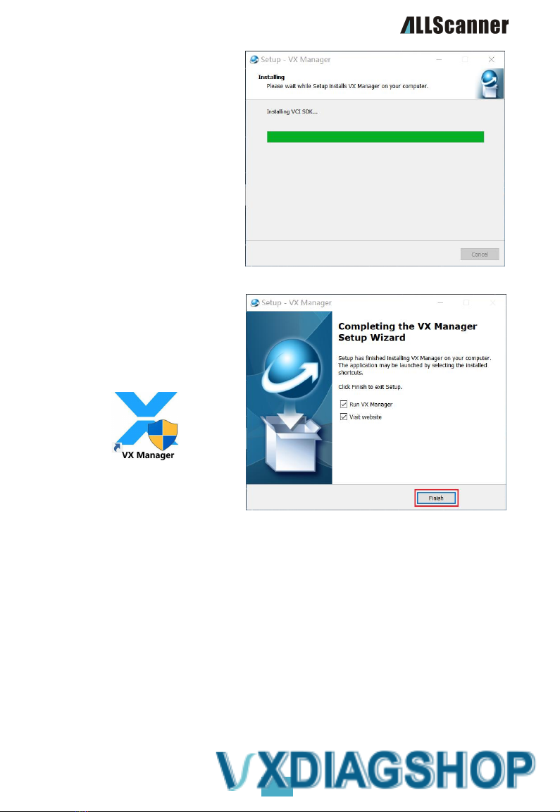
7. Installation in progress
8. Please be patient as the installation
process may take several minutes.
9. Installation complete
10. Click[Finish] to finish the installation.

28
Start of Use
Hardware Connection
Before using the equipment, the hardware must be correctly connected: the vehicle end of the equipment
is connected to the vehicle through OBD-II diagnostic cable, and there are three ways to connect the
equipment with the PC end:
The PC end of the device is connected to the PC via a USB communication cable
the PC side of that deviceis connecte to a PC via a LAN network cable
Device connected to P C via WIFI

29
USB connection
The first time you connect the USB cable to your PC, Windows prompts you to find new hardware and
automatically completes the driver installation.
The network adapter can be seen in the device manager after the driver is successfully installed: Realtek
USB FE Family Controller。
WIFI connection
The equipment is connected to the vehicle power supply and starts normally.
The computer searches for a wireless network:
DOIP-VCI-XXXX, select Auto Connect, and then
click Connect.
Enter the wireless network password: 12345678
Click Next.
30
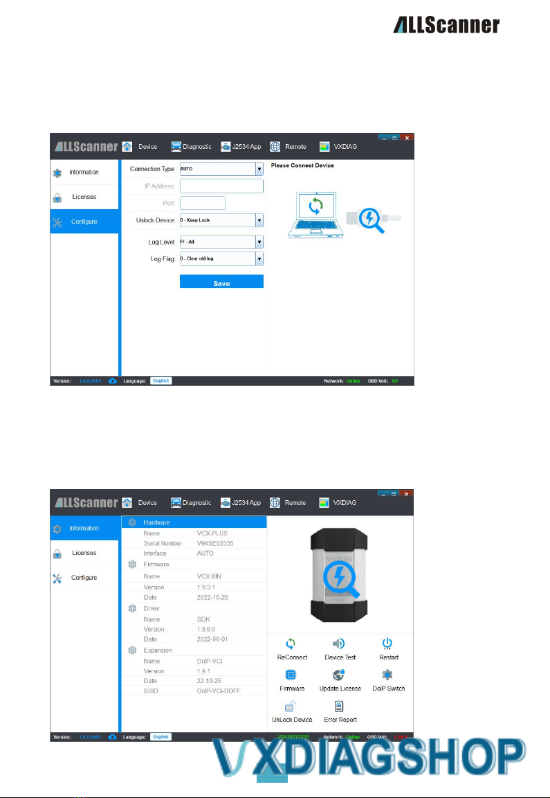
Device Connection Configuration
The VX Manager default connection type configuration is: AUTO automatic, can support automatic
identification of all connections, generally without modification. If you confirm that you need to modify
the connection type, you can modify it in the Device Management-> Device Configuration interface.
Device Connection Detection
After the device is properly connected as described above, start the VX Manager management software.
If the serial number, version, name and other information of the VCX device are displayed correctly, the
device is properly connected to the computer
31
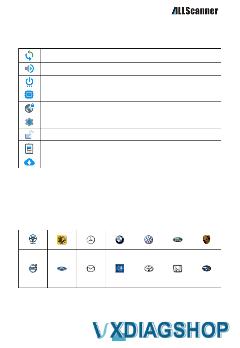
VX Manager Administrative Tools
Basic Functions
Reconnect
Reconnect the device and refresh the device information.
Equipment Testing
The device self-tests and the LEDs flash and beep.
Restart the device
The device is reset and restarted.
Update Firmware
Download and update the device firmware program online.
Update Authorization
Download and update device authorization data online.
DoIP switch
Test vehicle DoIP communication by activating or deactivating the
DoIP protocol.
release occupation
Manually release the equipment after it is occupied.
error report
View and get the device error log.
Check for updates
Check for updates to the VX Manager software.
Equipment Authorization
VCX devices manage device functionality through licenses (LICENSE), and the product you purchase may
include multiple licenses depending on model and configuration.
List of licensed features supported by the VCX series products:
DONET
PASSTHRU
BENZ
BMW
VW/AUDI
JLR
PORSCHE
VOLVO
FORD
MAZDA
GM
TOYOTA
HONDA
SUBARU
32
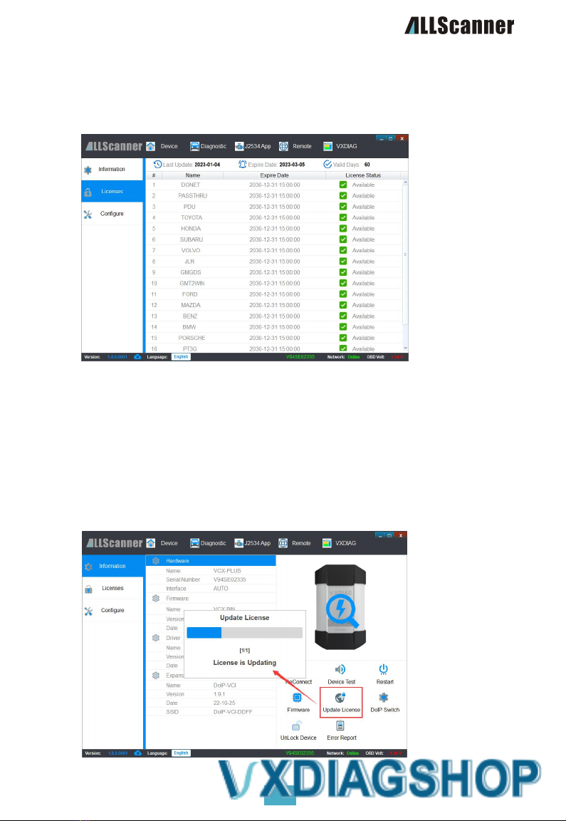
View Authorization
Connect the VCX device to the computer.
Running the VX Manager Management Software
Open the [Device Management]->[Device Authorization] page to see all authorization lists
supported by the current device.
Update Authorization
The VCX device license must be updated online regularly. If it is not updated for more than 60 days,
the device license will expire, which will affect the use of the authorized functions.
Updating your license requires your computer to be connected to the Internet.
By default, the VX Manager administration software automatically updates licenses when it is
started (update interval is 24 hours).
Connect the VCX device to the computer.
Run the VX Manager management software, which automatically updates the authorization when
it starts.
Click Update Authorization on Equipment Management-> Equipment Info to manually update
authorization.
33
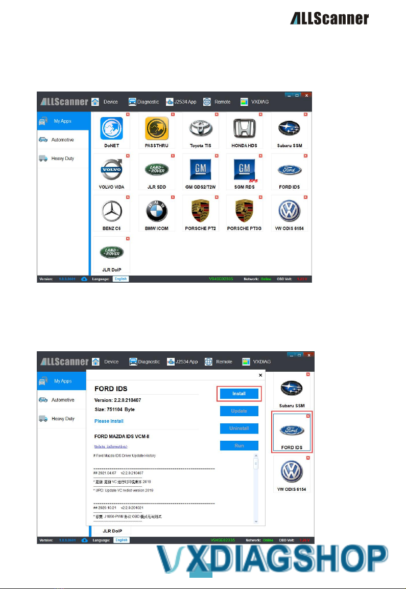
Diagnostics Driven Management
Start the VX Manager device management software, open the [Vehicle Diagnostics] tab, and click the [My
Applications] option on the left side of the page to display the licensed diagnostic drivers.
Install Diagnostic Driver
Open the [Vehicle Diagnosis]->[My Application] page, click the diagnosis application to be installed, such
as [FORD IDS], and the driver information interface will pop up. Click [Install] to start installing the driver.

34
Driver Installation Process
[Installation]V X Manager will obtain the latest diagnostic driver from the server and install it, and then
you can start using the original diagnostic function. The installation interface is as follows:
Update Diagnostic Driver
With the upgrade of the original software, the diagnostic driver is continuously optimized and updated.
Please always keep up to date!
Open the [Vehicle Diagnosis]->[My Application] page. When a diagnosis driver releases a new version,"+"
will be displayed in the upper right corner. Open the driver details and click [Update] to start upgrading
the driver.

35
warranty clause
One year limited warranty
1. The product warranty period is one year. The warranty start time and end time shall be based on
the date of supply invoice. If the invoice is lost, the purchase time shall be calculated according to
the factory date.
2. Under normal use conditions within the product warranty period, if the product or any part is
proved to be damaged due to design, material or process defects, the company will repair or
replace (new product or modified part) free of charge according to the situation with the warranty
card.
3. The freight for repair within the warranty period shall be paid by the supplier, and the freight for
repair after the warranty period shall be borne by the user.
4. The warranty service is only limited to the equipment itself, and the company is not responsible for
any damage other than the equipment.
5. For the computer equipment not directly assembled by the Company, the supplier shall be
responsible for the after-sales service of the computer part.
6. For the damage beyond the scope of warranty, Aocar will also provide normal warranty for
customers without charging maintenance fees. In case of replacement of materials, the user shall
be notified for approval, and the material cost and transportation cost shall be borne by the user.
The warranty does not apply to:
1. Any product damage caused by abnormal use or abnormal conditions, such as fire, soil, sand,
water, falling or extrusion, chemical corrosion, blown fuse, theft, improper use of power supply,
irresistible natural disasters,etc.
2. Damage caused by unauthorized disassembly, alteration, improper installation and maintenance.
3. Damage caused by an operation intended for an illegal purpose, such as reading or changing a
program in a device.
4. Products whose mechanical or electronic serial numbers have been deleted, altered, or destroyed.
5. Due to exposure to high temperatures or extreme environments.
6. Natural wear or damage of normal parts under the condition of conforming to relevant national
product quality regulations.
Services and Support
Technical support
You canvisit http://www.vxdiag.net the Wiki Technical Documentation Center at www.example.com,
which contains all the important documentation resources:
VXDIAGSoftware Installation and Use
Introduction and installation of various original diagnostic software
Various original diagnosis software test cases and videos

36
Maintenance services
If the device needs to be returned for repair, download and complete the Service Repair Form. Be sure to
fill in the following information:
Contact Name
Telephone number
Product Serial Number
Problem Description
warranty card
return address
Please contact us as follows:
address
Room A103-104, 1/F, Building A, Shenzhen Aerospace Science and Technology
Innovation Research Institute, No.6, Keji South 10th Road, South Hi-tech Zone,
Nanshan District, Shenzhen
Telephone
+86-0755-33000960
Zip Code
518057
Product
Consulting
info@allscanner.com
Technical
support
support@allscanner.com

Table of contents


