ALLSPEEDS Webtool HCV270 User manual

Instruction Manual
for
Allspeeds Ltd.
Royal Works, Atlas Street
Clayton Le Moors, Lancashire, UK.
BB5 5LW
HCV270
Allspeeds Product Code 980216
Allspeeds Document Revision 9. Issue 2
Mod. 21092
Date: 25/08/21
Original instructions

980216 –HCV270 Manual Page 2 of 22
Rev 9 Issue 2. Date: 25/08/2021
Table of Contents
1Important Notice –Read Before Use................................................................................... 3
2Introduction....................................................................................................................... 4
3Technical Data.................................................................................................................... 4
3.1 Physical......................................................................................................................................... 4
3.2 Hydraulic Requirements............................................................................................................... 4
3.3 Environmental Considerations ..................................................................................................... 5
3.4 Dimensions................................................................................................................................... 5
4Declaration of Conformity .................................................................................................. 6
5General Safety Rules .......................................................................................................... 7
5.1 Warnings....................................................................................................................................... 7
5.2 Important Information ................................................................................................................. 7
5.3 Safety for Operation..................................................................................................................... 7
5.4 Safety for Maintenance................................................................................................................ 8
5.5 Warning Symbols.......................................................................................................................... 8
6Installation......................................................................................................................... 9
6.1 Mounting Holes............................................................................................................................ 9
7Hydraulic Connections...................................................................................................... 10
8Operating Instructions...................................................................................................... 11
8.1 Before Use.................................................................................................................................. 11
8.2 Deploying the Tool ..................................................................................................................... 11
8.3 Pre-Cut Check............................................................................................................................. 12
8.4 Extend the Blade (Cut Cycle) ...................................................................................................... 13
8.5 Retract the Blade (Return Cycle) ................................................................................................ 13
9Maintenance.................................................................................................................... 14
9.1 Maintenance Notes.................................................................................................................... 14
9.2 Maintenance Schedule............................................................................................................... 14
9.3 Remove & Replace Anvil............................................................................................................. 15
9.4 Remove & Replace Blade............................................................................................................ 16
9.5 Seal Detail................................................................................................................................... 17
10 Parts List.......................................................................................................................... 19
11 Decommissioning............................................................................................................. 20

980216 –HCV270 Manual Page 3 of 22
Rev 9 Issue 2. Date: 25/08/2021
1Important Notice –Read Before Use
THIS IS AN INHERENTLY DANGEROUS PIECE OF CUTTING EQUIPMENT AND IS
SUPPLIED WITHOUT GUARDING. IT IS VITAL THAT THE INSTALLER AND END USER
PERFORM A RISK ASSESSMENT AND IMPLEMENT ANY SAFETY FEATURES THAT
THEY DEEM NECESSARY AND ENFORCE A SAFE SYSTEM OF WORK BEFORE USE.
Do not operate the main cutter cylinder unless the anvil is fully closed.
Ensure that the auxiliary cylinders remain pressurised (200 bar) throughout the
cut cycle to keep the anvil closed.
Read, understand and follow the instructions within the
operating manual before deploying or operating the HCV270 cutter.
Failing to follow the instructions and operating the cutter with a
partially closed anvil will result in serious damage to the HCV270.
IF IN DOUBT, ASK!
See section 8 for more details

980216 –HCV270 Manual Page 4 of 22
Rev 9 Issue 2. Date: 25/08/2021
2Introduction
This manual covers the installation, operation and maintenance of a HCV270 as Allspeeds part
number 980216
This is a double acting, hydraulically operated tool suitable for cutting cables and umbilical up to
270mm (10.5”) in diameter. It requires two separate dual line hydraulic supply (feed and return) for
the main cutter activation and the hydraulically operated anvil.
3Technical Data
HCV270 (part number 980216)
3.1 Physical
Weight of HCV270 in air 373.6 kg (excluding hydraulic fluid and hoses)
Weight of HCV270 in water 324.5 kg (excluding hydraulic fluid and hoses)
Overall Dimensions 706mm (883mm) x 250mm x 1148mm
3.2 Hydraulic Requirements
3.2.1 Main Cutter Cylinder
Cylinder Type Double acting (feed and return ports)
Maximum Operating Pressure 690 Bar (10,000 PSI)
Swept Volume Cut Stroke 5.3 Litre
Swept Volume Return Stroke 2 Litre
3.2.2 Anvil Auxiliary Cylinders
Cylinder Type Double acting (feed and return ports)
Maximum Operating Pressure 210 Bar (3,000 PSI)
Swept Volume Cut Stroke 0.132 Litre
Swept Volume Return Stroke 0.081 Litre
IMPORTANT –The maximum operating pressure stated above should not be exceeded during use of
this tool. Ensure that all fittings and hoses used are suitable for use at this pressure and rated
accordingly.
This HCV270 is compatible with the following hydraulic fluids:
Good quality hydraulic oil (e.g. Shell Tellus 32, 68 or similar)
Water glycol (e.g. Castrol Transaqua HT2).
Please note that whilst compatible, the use of water glycol fluids may reduce system life.
Ensure that the fluid used is cleaned to NAS Class 6 or better.

980216 –HCV270 Manual Page 5 of 22
Rev 9 Issue 2. Date: 25/08/2021
3.3 Environmental Considerations
This cutter should not be operated outside of the recommended temperature range of -5°C to +60°C.
This cutter is suitable for use subsea but should be regularly checked, cleaned and dewatered using a
suitable dewatering spray.
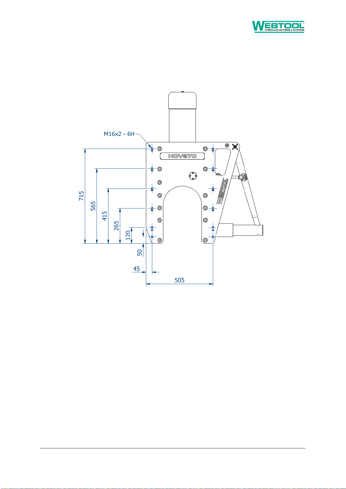
3.4 Dimensions
Figure 1 –Overall dimensions

980216 –HCV270 Manual Page 6 of 22
Rev 9 Issue 2. Date: 25/08/2021
4Declaration of Conformity
DECLARATION OF CONFORMITY
Company name:
Allspeeds Ltd
Company address:
Royal Works, Atlas Street, Clayton le Moors, Accrington, Lancashire
BB55LW, UK
Machinery covered by this
declaration:
Description:
Hydraulic Cutting Tool
Model:
980216
Type:
HCV270
Revision:
Rev 9
The machinery conforms to the following essential requirements
of the Machinery Directive 2006/42/EC:
The machinery also conforms to
the following Directives:
N/A
The following standards have
been applied:
N/A
This machinery must not be put into service until the machinery into which it is to be incorporated
has been declared in conformity with the provisions of the machinery directive
The technical documentation is compiled in accordance with part A of
Annex VII of the Machinery Directive 2006/42/EC
Person authorised to compile the
relevant technical documentation
(based in the European
Community):
Name:
Authorised Rep Compliance LTD.
Address:
71 Baggot Steet Lower, Dublin,
D02 P593, Ireland
The relevant authorised person undertakes to transmit, in response to a reasoned request by the national
authorities, relevant information on the machinery. This information will be transmitted by: (email, post)
Person authorised to make this
declaration:
Name:
Keith Elliot
Position in
company:
Managing Director
Signature :
Place of
Declaration:
Accrington, Lancashire, UK
Date of
Declaration:
4th January 2021

980216 –HCV270 Manual Page 7 of 22
Rev 9 Issue 2. Date: 25/08/2021
5General Safety Rules
5.1 Warnings
These warning are provided to improve safety and should be carefully read before installing, using or
maintaining the equipment.
5.2 Important Information
It is vital that these instructions are available to the equipment users. It is also important that they
are retained with the equipment if it is sold or transferred to another user.
5.3 Safety for Operation
IMPORTANT - This is an inherently dangerous piece of cutting equipment and is supplied without
guarding. It is vital that the installer and end user perform a risk assessment and implement any
safety features that they deem necessary and enforce a safe system of work before use.
To prevent the risk of injury, the cutter should only be used by fully trained and competent
operators.
•Make sure that all safety devices are in place and functioning correctly
•Make sure the working area is free of any obstructions
•Check that all hydraulic hoses are in good condition
•Ensure that all operators are clear of the area before cutting commences
Recommended PPE for operation and maintenance includes safety shoes, safety glasses, ear
defenders and gloves.
IMPORTANT - If the item being cut is under tension there is the risk of it recoiling when severed.
Ensure that all operators are out of the immediate area before operation.
Any spilt oil or trailing hoses may create a slipping or tripping hazard. Care must be taken around the
work area. Energised hoses may move during operation and should be fitted with whip-check devices
to contain them in case of a burst.

980216 –HCV270 Manual Page 8 of 22
Rev 9 Issue 2. Date: 25/08/2021
5.4 Safety for Maintenance
Repairs carried out by untrained or unauthorised personnel may result in personal injury or serious
malfunction of the tool.
Ensure that the cutter is isolated from and free of hydraulic pressure before any maintenance is
carried out.
5.5 Warning Symbols
General hazard. Hydraulic cutting tool with inherently
dangerous moving parts. Please read and understand this
manual to avoid the risk of injury.
Cut or severing hazard due to the cutting blade.
980216 –HCV270 Manual Page 9 of 22
Rev 9 Issue 2. Date: 25/08/2021
6Installation
6.1 Mounting Holes
The cutter body contains a number of mounting holes, as shown on the drawing below:
Figure 2 –Mounting holes
Ensure that the tool is securely mounted at multiple points and that mounting method is robust
enough to support the tool. Consult tool mass in section 3.1 when considering mounting possibilities.
980216 –HCV270 Manual Page 10 of 22
Rev 9 Issue 2. Date: 25/08/2021
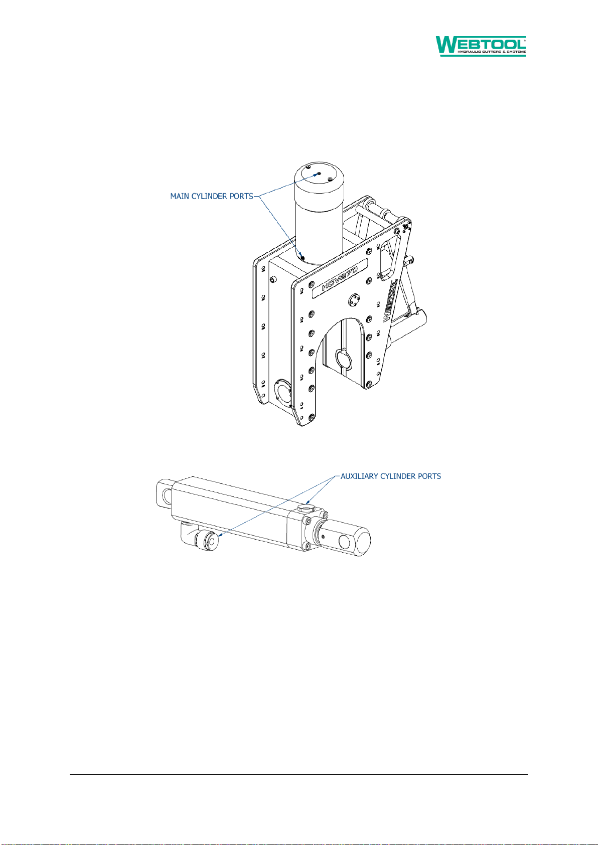
7Hydraulic Connections
The HCV270 contains two double acting hydraulic circuits and should be connected to a suitable
hydraulic supply (not supplied). Note that return port orientation may not be in line with cutter body
as shown. Please allow ±15° when planning hydraulic connections.
Figure 3 –Hydraulic ports
Main cylinder ports are 3/8” NPT
Auxiliary cylinder ports are 1/4” NPT
It is the responsibility of the end user to ensure that a suitable hydraulic supply is installed. It is
recommended that a relief valve should also be incorporated in the return line to prevent excessively
high pressures in the annular side of the hydraulic cylinders should the return to tank become
blocked for any reason.

980216 –HCV270 Manual Page 11 of 22
Rev 9 Issue 2. Date: 25/08/2021
8Operating Instructions
8.1 Before Use
With the hydraulic supply isolated, check the following parts of the cutter:
Item
Procedure
Check the condition of the anvil
As described in section 9.3
Check the condition of the blade
As described in section 9.4
Before use of the tool, ensure that all operators are at a safe distance from the cutter, and that any
guarding or safety features are installed and operational.
Check that the hydraulic supply is set to an appropriate level for operation as stated in section 3.2.
8.2 Deploying the Tool
Begin the operation with the anvil fully retracted. To achieve this, pressurise the ‘Anvil Out’ port on
the HCV270 auxiliary cylinder.
Place the cutter over the workpiece. Ensure that the workpiece is fully inserted into the mouth of the
tool so that there is no risk of the anvil fouling against it as it is closed.
Close the anvil over the workpiece by pressurising the ‘Anvil In’ port on the HCV270 auxiliary
cylinder. Ensure that the ‘Anvil Out’ port is open to tank.
Fully inspect the tool to ensure the anvil is fully closed before continuing.
Figure 4 –Rope position
980216 –HCV270 Manual Page 12 of 22
Rev 9 Issue 2. Date: 25/08/2021
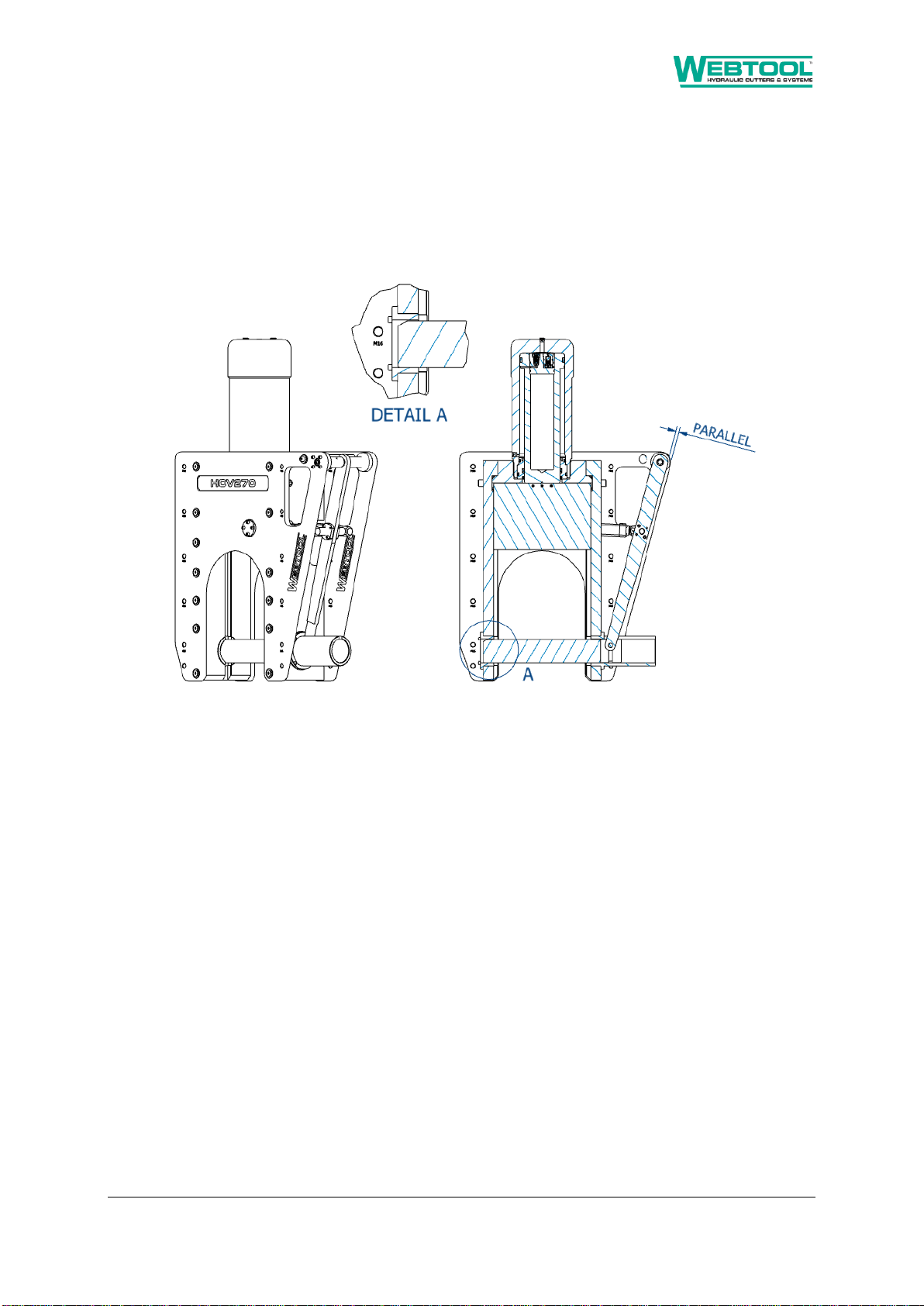
8.3 Pre-Cut Check
It is vital to ensure that the anvil is fully closed before any cut is attempted. Visually inspect the
closed tool, ideally from multiple angles to ensure that the anvil Is fully inserted into the opposing
anvil bush.
In its fully closed position the anvil lever should be parallel with the cutter body as shown below.
Figure 5 –Anvil check

980216 –HCV270 Manual Page 13 of 22
Rev 9 Issue 2. Date: 25/08/2021
IMPORTANT - Ensure that the anvil is fully closed before
performing a cutting operation.
IMPORTANT - Maintain pressure on the auxiliary anvil instroke to
keep the anvil closed throughout the cut cycle.
DO NOT OPERATE THE MAIN RAM IF THE ANVIL IS NOT FULLY
CLOSED AND PRESSURISED
8.4 Extend the Blade (Cut Cycle)
To extend the blade, pressurise the ‘Blade Down’ port on the HCV270 main cylinder whilst ensuring
that the ‘Blade Up’ port is open to tank. Do not exceed the maximum operating pressure. Continue
to apply pressure until the cut is complete.
IMPORTANT –Do not attempt to open the anvil without first retracting the main
ram.
8.5 Retract the Blade (Return Cycle)
To retract the blade, pressurise the ‘Blade Up’ port on the HCV270 main cylinder whilst ensuring that
the ‘Blade Down’ port is open to tank. Do not exceed the maximum operating pressure.

980216 –HCV270 Manual Page 14 of 22
Rev 9 Issue 2. Date: 25/08/2021
9Maintenance
It is unlikely that service would be required on the hydraulic piston of the tool under normal
circumstances, but a seal spares kit is available (995288) and it is recommended to stock this at all
times.
The only parts that would need intermittent replacement would be the anvil and blade depending on
the frequency of use, materials being cut and the corrosive conditions present during operation.
IMPORTANT - Replacement parts must always be sourced from Allspeeds Ltd. The use of unofficial
components will invalidate the warranty and may lead to tool damage or system failure.
9.1 Maintenance Notes
IMPORTANT –This cutter should only be serviced by qualified personnel. If in any doubt please
contact Allspeeds Ltd or a distributor.
Most maintenance task can be carried out with standard tools.
All servicing operations should be carried out in a clean environment to prevent contamination of the
oil and mating components.
Care should be taken with all mating areas, including threads and sealing faces, as any damage or
abrasive contamination could cause galling or seizing on re-assembly. Please note a suitable anti-
galling paste should be used (we recommend Swagelok Silver Goop) on all stainless steel threads.
The main cylinder (728075) is a pressure vessel and should not be drilled, machined, mutilated or
damaged in any way for mounting purposes or to assist in its removal for servicing, any warranty
could be invalidated by such actions.
The use of a Stilson wrench to remove the cylinder is not recommended as damage will occur.
Before carrying out any maintenance tasks ensure that the equipment is fully isolated and that there
is no residual pressure in the system.
9.2 Maintenance Schedule
This tool requires the following operations or service tasks to be completed as listed:
Task
See section
Frequency
Visual inspection of blade and anvil
9.3, 9.4
14 days or after cut, whichever is soonest.
Function test (extend and retract ram)
8.4, 8.5
14 days if unused
Clean and dewater
7 days
Replace blade
9.4
As required
Replace anvil
9.3
As required
Replace seals
9.5
12 months
Table 1 –Maintenance schedule

980216 –HCV270 Manual Page 15 of 22
Rev 9 Issue 2. Date: 25/08/2021
9.3 Remove & Replace Anvil
IMPORTANT –The anvil may have sharp edges and imbedded material left behind from cutting
operations. Wear suitable gloves when handling the anvil.
IMPORTANT –Ensure that the hydraulic supply is isolated before proceeding.
IMPORTANT - Replacement parts must always be sourced from Allspeeds Ltd. The use of unofficial
components will invalidate the warranty and may lead to tool damage or system failure.
Begin the operation with the anvil fully retracted. To achieve this, pressurise the ‘Anvil Out’ port on
the HCV270 auxiliary cylinder.
Loosen the 8 off M6 screws (035079) holding pivot pin housings (749045A & B).
Loosen the M6 retaining screw (035073).
Figure 6 –Anvil Replacement
Withdraw the pivot pin (761267) far enough to release the lever arm. (There is an M6 tapped hole in
the end of the pivot pin to assist in withdrawing)
The lever arm can now be moved upwards to separate it from the anvil (SSC6488). The anvil may
now be slid out from the guide bush. Re-assembly is the reverse of the above process.
IMPORTANT –Mass of anvil (SSC6488) is 17.7kg. Ensure a safe system of work at all times.

980216 –HCV270 Manual Page 16 of 22
Rev 9 Issue 2. Date: 25/08/2021
9.4 Remove & Replace Blade
IMPORTANT - The cutting edge may be sharp following tool operation, extreme caution and care
should be taken when checking it. Wear suitable gloves when handling the blade.
IMPORTANT - Ensure that the hydraulic supply is isolated before proceeding.
IMPORTANT - Replacement parts must always be sourced from Allspeeds Ltd. The use of unofficial
components will invalidate the warranty and may lead to tool damage or system failure.
The blade edge should be regularly checked to ensure that it is in good condition. This would be a
consistent blade edge with no chips or deformations noted along the entire cutting edge.
For safety we recommend that this operation is performed with the tool led down.
Begin with the anvil removed as described in section 9.3. The main cylinder should be in its fully
extended position. To extend the blade, pressurise the ‘Blade Down’ port on the HCV270 main
cylinder whilst ensuring that the ‘Blade Up’ port is open to tank
Remove the 3 off blade retaining pins (030636) using a suitably sized drift. Once blade retaining pins
are removed the blade is free to slide in the tool, care must be taken to prevent the blade from
falling or causing injury to operator.
IMPORTANT –Mass of blade (705050C) is 13kg. Ensure a safe system of work at all times.
Figure 7 –Blade Removal
Blade replacement is the reverse of the disassembly procedure.

980216 –HCV270 Manual Page 17 of 22
Rev 9 Issue 2. Date: 25/08/2021
9.5 Seal Detail
IMPORTANT –Ensure that the hydraulic supply is isolated before proceeding.
IMPORTANT - Replacement parts must always be sourced from Allspeeds Ltd. The use of unofficial
components will invalidate the warranty and may lead to tool damage or system failure.
IMPORTANT –Changing the seals will likely result in oil spills. Hydraulic oil spills present slip hazards.
Ensure a safe system of work at all times.
If it is necessary to inspect or renew the hydraulic seals, the cylinder must be removed from the tool.
As an aid to this, 2 off tapped holes are provided in the cylinder end face. These are M10 x 12mm
deep on 130mm PCD. Never use Stilsons or pipe clamps on the cylinder as damage may occur. If in
doubt contact Allspeeds for advice.
A cylinder assembly tool is available if required from Allspeeds (SK4377A).
Begin operation with the blade removed. See section 9.4 for this procedure.
Firstly, remove the coupling, hose and blanking plugs (035256) from the top of the tool and attach
the cylinder assembly tool (SK4377A). This can be used to loosen or re-tighten the cylinder.
IMPORTANT –Mass of Cylinder (728075) is 55.5kg and Ram (764113) is 26.7kg. Ensure a safe system
of work at all times.
Unscrew the cylinder and remove from the assembly. Use M10 holes to facilitate safe lifting. Care
should be taken as any contained oil within the cylinder will now be free to spill in the work area. The
cylinder will come free but seal stiction may mean that the ram comes also. If this happens, carefully
lay the cylinder assembly down in a safe location, connect a handpump or other hydraulic supply to
the cylinder and pump the ram out of the cylinder. Again, care should be taken as any contained oil
within the cylinder will now be free to spill in the work area.
Figure 8 –Cylinder Removal

980216 –HCV270 Manual Page 18 of 22
Rev 9 Issue 2. Date: 25/08/2021
The ram is fitted with relief valve plug assembly (991015) which also contains seals. To remove this,
locate off the two M8 x 12mm deep holes and unscrew the plug. The two relief valves have been
carefully set to operate at a set pressure and care should be taken not to disturb the settings during
removal. Remove these parts with a 17mm socket and 5mm hex bit.
With these parts now separate and the bearing ring (774032) now accessible, all main seals can be
seen and replaced.
Figure 9 –Seal access
Figure 10 –Main seal assembly

980216 –HCV270 Manual Page 19 of 22
Rev 9 Issue 2. Date: 25/08/2021
10 Parts List
The cutter comprises the following components:
Part Number
Description
Qty
026701
Pellet
2
030636
Pin spring 1/4" x 2"
3
035066
Socket head cap screw M6 x 20
8
035067
Socket head cap screw M5 x 30
8
035073
Set screw cup point M6 x 10
1
035079
Socket head cap screw M6 x 25
16
035111
Socket head cap screw M6 x 35
4
035113
Socket button head screw M6 x 16
5
035256
M10 x thread plug
2
043206
Skt set screw - cup point - M4 x 6
2
079043
Auxiliary cylinder mounting stud
2
080971
Washer M6
4
082223
M12 bonded seal
2
31-99-2834
Eyebolt din 580 - M16
4
701195
90 degree elbow
2
705050c
Blade
1
709062
Auxiliary cylinder ram head
2
715345
Pivot pin lever bush
2
715348
Anvil guide bush
1
715350
Anvil bush
1
728075
Cylinder
1
728077
Auxiliary cylinder body
2
749045A
Pivot pin housing
1
749045B
Pivot pin housing
1
761247
Anvil pin
1
761249
Auxiliary cylinder rod pin
2
761267
Lever pivot pin
1
764113
Ram
1
764115
Auxiliary piston
2
765212
Lever
1
766047
Plastic plug for hydraulic anvil
4
774032
Bearing ring
1
982167
Body assembly
1
991015
Relief valve kit
1
SSC6476
Auxiliary cylinder end cap
2
SSC6488
Anvil
1
Table 2 –Parts list

980216 –HCV270 Manual Page 20 of 22
Rev 9 Issue 2. Date: 25/08/2021
11 Decommissioning
Major components are made from the following recyclable materials:
Description
Material
Body
Alloy steel
Cylinder
Alloy Steel
Ram
Alloy steel
Anvil
Stainless bronze
Blade
Tool steel
Guide Bush
Aluminium bronze
Table 3 –Materials of Construction
Remaining components should be disposed of in accordance with local current regulations.
Hydraulic fluid should be drained into a suitable container and disposed of in accordance with
current local regulations.
Table of contents


