Allstate 788.94495 Use and care manual
--I
OPERATING
INSTRUCTIONS
AND
PARTS
LIST
FOR
MOTOR SCOOTER
r------MODEL
NUMBER
788.94495------
This
is
the
Model
Number
of
your
Allstate
Motor
Scooter.
It
will
be
found
on
a
plate
fastened
to
chassis
under
the
fuel
cock.
Always
mention
this
number
when
communicating
with
us
regarding
the
Scooter.
or
when
ordering
parts.
HOW
TO
ORDER REPAIR PARTS
All
parts
listed
herein
may
be
ordered
through
any
Sears
retail
or
mail
order
store.
In
ordering
parts
by
mail
from
the
mail
order
store
which
serves
the
territory
in
which
you
live.
Selling
Prices
will
be
furnished
on
request
or
parts
will
be
shipped
at
prevailing
prices
and
you
will
be
billed
accordingly.
WHEN
ORDERING REPAIR PARTS. ALWAYS GIVE THE
FOL-
LOWING
INFORMATION:
1.
-
The
Part
Number
in
this
List.
2. -
The
Part
Name
in
this
List.
3. -
The
Model
Number
of
the
item.
This
list
is
valuable.
It
will
assure
your
being
able
to
obtain
proper
parts
service
at
all
times.
We
suggest
you
keep
it
with
other
valuable
papers.
...
co.
AND
.
Printed
in U.S.A.
ROEBUCK
SEARS,
F-1716
I
11-=-1
=============================================-.~
I
821762
1
INTRODUCTION
This
model
of
motor
scooter
has
a
new
and
modern
type
of
engine
in
which
the
distribution
is
realised
by
the
crankshaft
(rotary
valve
di-
stribution).
The
carburettor,
installed
on
the
crankcase,
is in
direct
communication
with
the
pre-compres-
sion
chamber
in
corrispondence
to
the
external
diameter
of
one
of
the
crankshaft
flywheels
(see
fig. 11):
the
periphery
of
the
flywheel
rotates
very
close
to
the
crankcase,
without
touching
it;
a
portion
in
the
periphery
of
said
web
is
ground
off,
and
controls
the
fuel flow to
the
pre-com-
pression
chamber,
thus
acting
as
a
rotary
valve.
The
recess
on
the
web
periphery
has
been
shaped
in
such
a
way
as
to
give
the
maximum
volumetric
efficiency,
an
asymmetrical
distribution
diagram
being
achieved.
It
must
be
noted
that
crankweb
and
crank-
,
case
are
kept
gas
tight
by
'the
film of oil
which
forms
between
them
and
not
by
direct
contact;
in this
way
the
system
is
not
subject
to
wear
by
friction,
as
is
usually
the
case
with
similar
devices.
The
intake
pipe
is
very
short; it is
therefore
only
the
carburettor
which
slows
down
the
flow
of
fresh
charge
to the
engine.
The
advantages
oJ
a
correct
feeding
system
are
therefore
clear;
more
power
with
low
revs,
and
so
a
more
elastic
engine.
The
intake
pipe
leads
therefore
into
the
pre-compression
chamber
and
the fresh
charge
contacts
directly
the
con.
rod
big
end;
in this
way
the
bearings
are
so
efficiently
lubricated
as
to
permit
reduci<1g,
the
percentage
of
oil in
the
gasoline
(2"10).
The
improvement
which
the
rotary
valve
brings
to
the
thermo-dynamic
performance
of
the
engine
can
be
appreciated
by
considering
the
flatness
of
the
power
curve;
this,
as
is
well
known,
makes
the
engine
capable
of
functioning
on
a
wide
rpm
range
and
of
adjusting
itself
automa-
tically,
with
slight
variation
of
speed,
to
all
forms
or
resistance
which
the
scooter
must
overcome
(head
wind,
gradients
etc.).
The
proverbial
climbing
ability
of
this
motor
scooter
is
enhanced
in
this
model.
All
gradients
normally
encountered
on
main
roads
can
easily
be
climbed
in
3rd
gear,
even
with
two
people
on
board;
any
slope
can
be
climbed
at
speed
in
2nd
gear,
while
the
1st
gear
gives
initial
acce-
leration
and
is
particularly
useful
on
bad
surfaces
and
side
roads.
Another
advantage
of
the
rotary
valve
is
that
it
eliminates
back
pressure,
i.
e.
prevents
some
of
the
fresh
fuel from
being
pushed
back
from
the
pre-compression
chamber
towards
the
carburetttor
and
wasted,
at
the
beginning
of
the
dovrnward
stroke
of
the
piston.
Engine
performance
is
also
improved
by
the
adoption
of a
spherical
headed
piston
and
a
com-
bustion
chamber
on
the
cylinder
head
of a
special
form
which
gives
rise
to
higher
turbulence,
thus
resulting
in
higher
compression
ratio
and
thence
increase
in
both
specific
power
and
out-put.
Finally
the
carburettor,
which
is
housed
in
the
air
cleaner,
is
similar
to
those
used
in
the
car
industry,
with
plate-shaped
slide
valve
and
immersed
jets: this
has
reduced
fuel
consumption
and
improved
the
general
performance
of
the
engine.
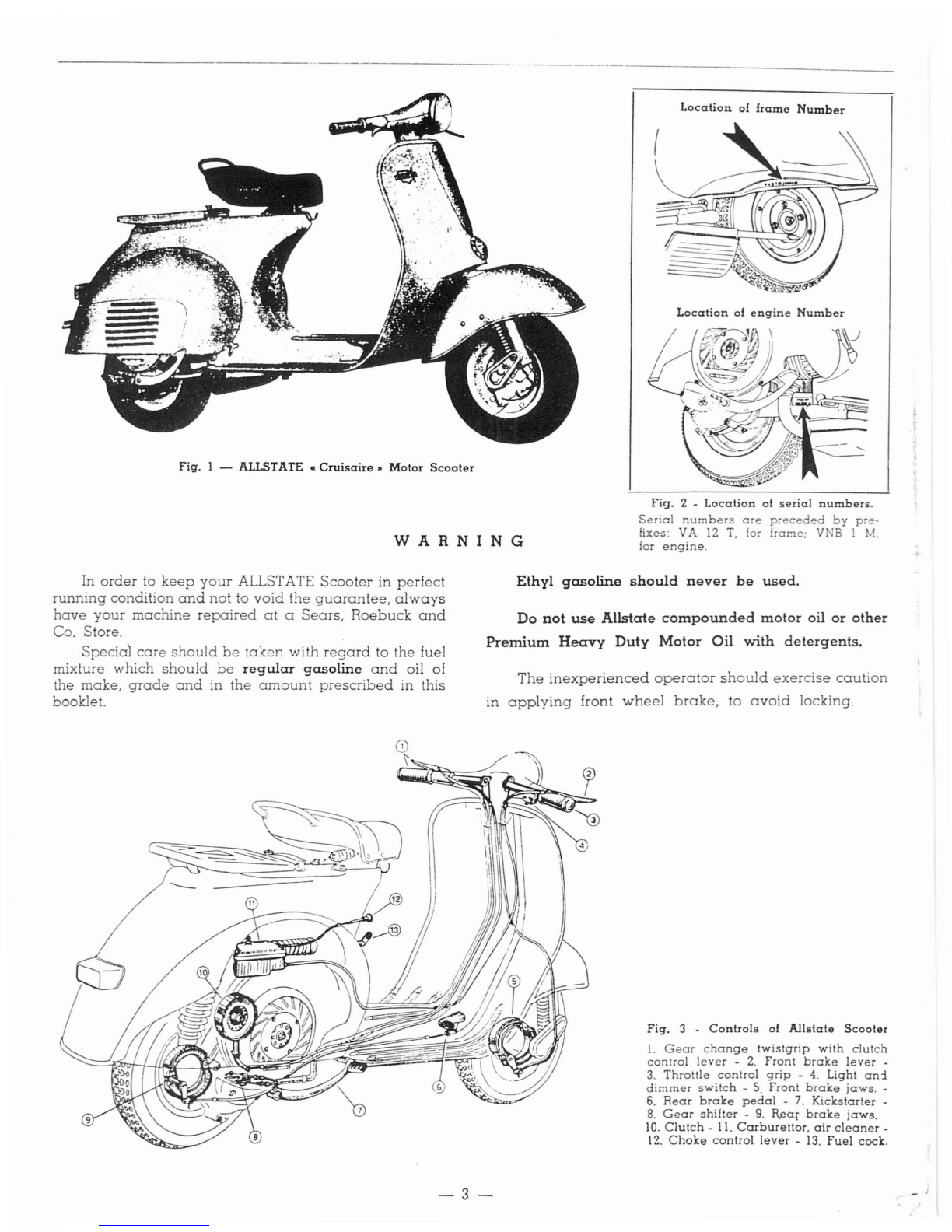
fig.
1 -
ALLSTATE.
Cruisaire.
Motor
Scooter
WARNING
Location
of
frame
Number
Location
of
engine
Number
fig.
2 -
Location
of
serial
numbers.
Serial
numbers
are
preceded
by
pre-
fixes: VA
12
T.
for
frame;
V
18
I
M.
for
engine.
In
order
to
keep
your
ALLSTATE
Scooter
in
perfect
running
condition
and
not
to
void
the
guarantee,
always
have
your
machine
repaired
at
a
Sears,
Roebuck
and
Co. Store.
Special
care
should
be
taken
with
regard
to
the
fuel
mixture
which
should
be
regular
gasoline
and
oil of
the
make,
grade
and
in
the
amount
prescribed
in this
booklet.
Ethyl
gasoline
should
never
be
used.
Do
not
use
Allstate
compounded
motor
oil
or
other
Premium
Heavy
Duty
Motor
Oil
with
detergents.
The
inexperienced
operator
should
exercise
caution
in
applying
front
wheel
brake,
to
avoid
locking.
fig.
3 -
Controls
of
Allstate
Scooter
1.
Gear
change
twistgrip
with
clutch
control
lever
-
2.
Front
brake
lever
-
3.
Throttle
control
grip
-
4.
Light
an:!
dimmer
switch
-
S.
Front
brake
jaws.
-
6.
Rear
brake
pedal
-7.
Kickstarter
-
8.
Gear
shifter
-
9.
R,ear
brake
jaws.
10.
Clutch
-
11.
Carburellor.
air
cleaner
-
12.
Choke
control
lever
-
13.
fuel
cock.
-3-

Fig.
4 -
Engine
installation
and
suspensions.
!.
Steering
column
and
front
suspension
-
2.
Engine
-
3.
Crankcase
half.
clutch
side,
with
swinging
arm
-
4.
Rear
suspension
spring
with
hydraulic
damper.
MAIN
SPECIFICATIONS
Frame.
-Of
pressed
and
spot-welded
steel
sheet,
with
stream-lined
monocoque-type
structure.
Suspension.
-Front
wheel:
coil
spring.
Rear
wheel:
coil
spring
and
coaxial
hydraulic
shock
absorber.
Engine. -Two-stroke, flat
cast
iron
cylinder
and
cast
aluminium
alloy
cylinder
head.
Cooling
effected
by
centrifugal fan.
Displacement
123.4
cc.
(7.53
cu. in.)
Bore.
.
52.5
mm. (2.06 in.)
Stroke
57
mm.
(2.24
in.)
Effective
power
at
5000
rpm
4.6 HP.
Compression ratio . 7 : 1
Transmission. -Directly from
engine
to
rear
wheel
through
clutch, cushiOn
drive
and
gear
box.
Starting.
-By
means
of kickstarter,
right
hand
side
of
scooter.
Fuel
consumption:
(Gasoline -oil mixture)
Max.
speed.
Wheel
base.
Max.
width
on
handlebars
Max.
length
of
the
scooter
Max.
height.
Min.
height
of
floorboard
.
Tuming
circle .
Weight
(unladen)
130
miles
per
gal.
46-.6
m.p.h.
46.4 in.
25.7
in.
68.2 in.
38.7
in.
8in.
59
in.
182
Ibs.
Gear
box.
-
3-speed
drive
with
mesh
gears
in
oil
bath.
Its
two-cable
control
is
coupled
with
that
of
the
clutch,
on
left
hand
side
of
handlebars.
Engine
to
wheel
transmission
ratios:
First
12.2
to 1
Second
7.6
to
1
Third.
4.85
to 1
Clutch.
-
Wet
type;
multiplate,
with
facings
of
cork
composition
applied
to
the
driving
discs.
Ignition.
-
By
flywheel
magneto.
.--------/-1
6
3
Fig.
5 -
Ignition
diagram
1.
Ignition
coil
in
flywheel
magneto
_
2.
Rotor
cam
-
3.
Breaker
_
4.
Condenser
-
S.
Sparkplug
-
6.
Engine
cut-out
on
switch.
-4-
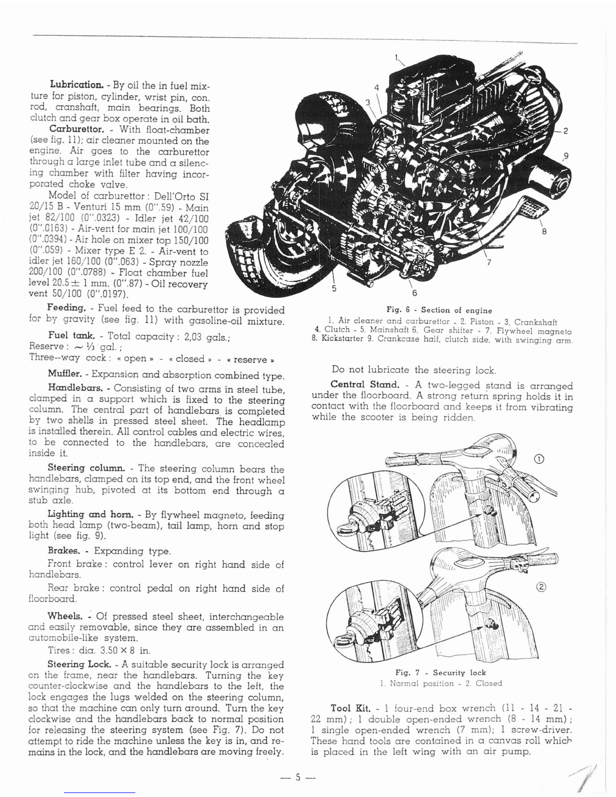
Lubrication. -By oil
the
in fuel mix-
ture for piston, cylinder, wrist pin, con.
rod,
cranshaft,
main
bearings.
Both
clutch
and
gear
box
operate
in oil
bath.
Carburettor. -With
float-chamber
(see
fig.
11);
air
cleaner
mounted
on
the
engine. Air
goes
to
the
carburettor
through
a
large
inlet
tube
and
asilenc-
ing
chamber
with filter
having
incor-
porated
choke
valve.
Model of
carburettor:
Dell'Orto SI
20/15 B - Venturi
15
mm
(0".59) -
Main
jet 82/100
(0".03.2.3)
-
Idler
jet
42/100
(0".0163) -Air-vent for
main
jet
100/100
(0".0394) -Air hole
on
mixer
top
150/100
(0".059) -Mixer
type
E
2.
-Air-vent to
idler jet 160/100 (0".063) -
Spray
nozzle
200/100 (0".0788) -
Float
chamber
fuel
level 20.5 ±1mm. (0".87) -Oil
recovery
vent 50/100 (0".0197).
Feeding. -
Fuel
feed
to
the
carburettor
is
provided
for
by
gravity
(see fig. 11)
with
gasoline-oil
mixture.
Fuel tank. -Total
capacity:
2,03 gals.;
Reserve:
,-.J
1/
3.
gal.
;
Three--way
cock:
«
open»
-«
closed»
-
«reserve»
Muffler. -
Expansion
and
absorption
combined
type.
Handlebars. -
Consisting
of
two
arms
in
steel
tube,
clamped
in a
support
which
is fixed to
the
steering
column. The
central
part
of
handlebars
is
completed
by
two shells in
pressed
steel
sheet.
The
headlamp
is installed therein. All control
cables
and
electric
wires,
to
be
connected
to
the
handlebars,
are
concealed
inside it.
Steering column. -The
steering
column
bears
the
handlebars,
clamped
on
its
top
end,
and
the
front
wheel
swinging
hub,
pivoted
at
its
bottom
end
through
a
stub
axle.
Lighting
and
hom.
-By flywheel
magneto,
feeding
both
head
lamp
(two-beam),
tail
lamp,
horn
and
stop
light (see
fig.
9).
Brakes. -
Expanding
type.
Front
brake:
control
lever
on
right
hand
side
of
handlebars.
Rear
brake:
control
pedal
on
right
hand
side
of
floorboard.
Wheels.
~
Of
pressed
steel
sheet,
interchangeable
and
easily
removable,
since
they
are
assembled
in
an
automobile-like
system.
Tires:
dia. 3.50 x8in.
Steering Lock. -A
suitable
security
lock is
arranged
on
the frame,
near
the
handlebars.
Turning
the
key
counter-clockwise
and
the
handlebars
to
the
left,
the
lock
engages
the
lugs
welded
on
the
steering
column,
so that the
machine
can
only
turn
around.
Turn
the
key
clockwise
and
the
handlebars
back
to
normal
position
for
releasing
the
steering
system
(see
Fig. 7). Do
not
attempt
to ride the
machine
unless
the
key
is in,
and
re-
mains
in
the
lock,
and
the
handlebars
are
moving
freely.
5
Fig.
6 -
Section
of
engine
1.
Air
cleaner
and
carburet
tor _
2.
Piston
-
3.
Crankshaft
4.
Clutch
-
5.
Mainshaft
6.
Gear
shifter
-
7.
Flywheel
magneto
8.
Kickstarter
9.
Crankcase
half.
clutch
side,
with
swing:ng
arm.
Do
not
lubricate
the
steering
lock.
Central Stand. -A
two-legged
:;tand
is
arranged
under
the
floorboard.
A
strong
return
spring
holds
it in
contact
with
the
floorboard
and
keeps
it from
vibrating
while
the
scooter
is
being
ridden.
Fig.
7 -
Security
lock
1.
Normal
position
-
2.
Closed
Tool
Kit.
- I
four-end
box
wrench
(II
-
14
-
21
-
22
mm);
1
double
open-ended
wrench
(8
-
14
mm);
1
single
open-ended
wrench
(7
mm); 1
screw-driver.
These
hand
tools
are
contained
in a
canvas
roll
which
is
placed
in
the
left
wing
with
an
air
pump.
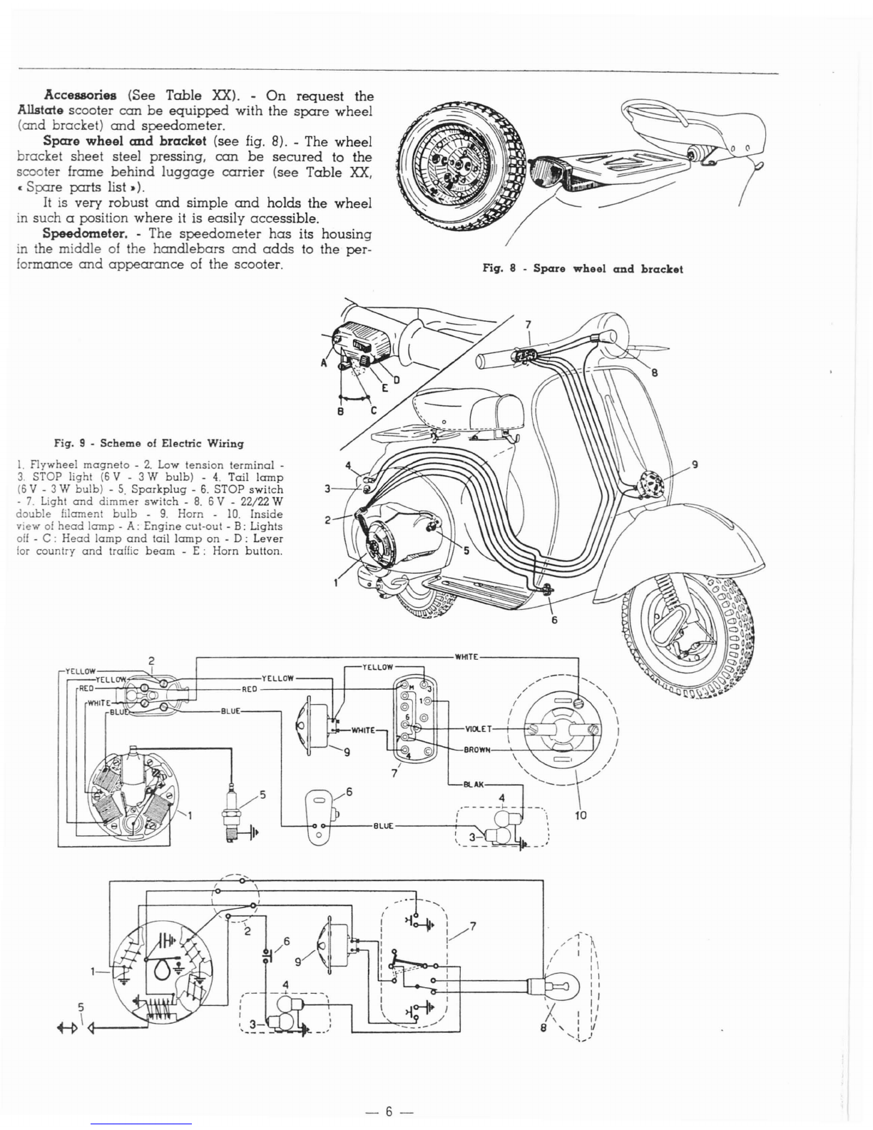
Accessories (See
Table
XX).
-
On
request
the
Allstate scooter
can
be
equipped
with
the
spare
wheel
(and
bracket)
and
speedometer.
Spare
wheel
and
bracket (see fig. 8). -The
wheel
bracket
sheet
steel pressing,
can
be
secured
to
the
scooter frame
behind
luggage
carrier
(see
Table
XX,
c
Spare
parts
list
.).
It is very
robust
and
simple
and
holds
the
wheel
in
such
aposition
where
it is
easily
accessible.
Speedometer. -The
speedometer
has
its
housing
in the middle
of
the
handlebars
and
adds
to the
per-
formance
and
appearance
of the scooter.
Fig.
8 -
Spare
wheel
and
bracket
.--------------------
WHlTE------_
9
BRDWII---"---',-"",--,,"--J/
~l*-4+--+--V1OLET-I--~
2
o-I----BLut
----.-.---...
~~~~---BLUE-----,
2
YELLOW~U;;p~I~~_t-
_
YELL YELLOW
REO---r-~I"0~~~+---
REO
-----+-1------1(;:
Fig. 9 -
Scheme
of Electric
Wiring
1.
Flywheel
magneto
-
2.
Low
tension
terminal
-
3.
STOP light
(6
V - 3 W
bulb)
-
4.
Tail
lamp
(6
V - 3 W
bulb)
-
5.
Sparkplug
-
6.
STOP
switch
-
7.
Light
and
dimmer
switch
-
8.
6 V - 22/22 W
double
filament
bulb
-
9.
Horn -
10.
Inside
view
of
head
lamp
-A:
Engine
cut-out
-
B:
Lights
off
- C :
Head
lamp
and
tail
lamp
on
-
D:
Lever
lor
country
and
traffic
beam
-
E:
Horn
bulton
.
5
~\<1----I-
-6-
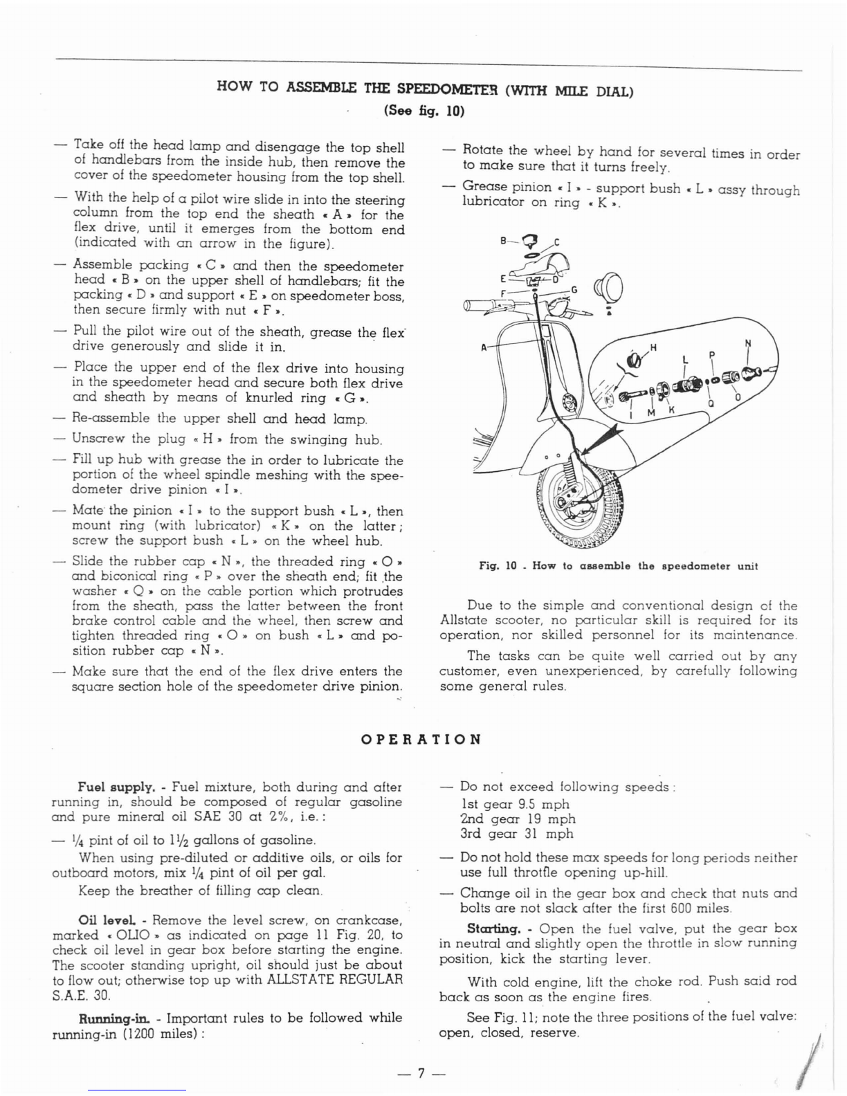
HOW
TO
ASSEMBLE
THE
SPEEDOMETER
(WIm
MILE
DIAL)
(See fig. 10)
-
Take
off
the
head
lamp
and
disengage
the
top
shell
of
handlebars
from
the
inside
hub,
then
remove
the
cover
of the
speedometer
housing
from
the
top
shell.
-With
the
help
of apilot
wire
slide
in
into
the
steerihg
column
from
the
top
end
the
sheath
cA.
for
the
flex drive, until it
emerges
from
the
bottom
end
(indicated
with
an
arrow
in
the
figure).
-
Assemble
packing
c
C.
and
then
the
speedometer
head
c
B.
on
the
upper
shell
of
handlebars;
fit
the
packing
cD.
and
support
c E •
on
speedometer
boss,
then
secure
firmly
with
nut
c F •.
-Pull
the
pilot
wire
au
tof
the
sheath,
grease
the
flex'
drive
generously
and
slide
it in. .
-
Place
the
upper
end
of
the
flex
drive
into
housing
in
the
speedometer
head
and
secure
both
flex
drive
and
sheath
by
means
of
knurled
ring
c G •.
-
Re-assemble
the
upper
shell
and
head
lamp.
-
Unscrew
the
plug
«H.
from
the
swinging
hub.
-Fill
up
hub
with
grease
the
in
order
to
lubricate
the
portion
of the
wheel
spindle
meshing
with
the
spee-
dometer
drive
pinion
c I •.
-Mate'
the
pinion
c
I.
to
the
support
bush
c L
.,
then
mount
ring
(with
lubricator)
«K.
on
the
latter;
screw
the
support
bush
c
L.
on
the
wheel
hub.
-
Slide
the
rubber
cap
eN.,
the
threaded
ring
cO.
and
biconical
ring
c P •
over
the
sheath
end;
fit
.the
washer
cQ •
on
the
cable
portion
which
protrudes
from the
sheath,
pass
the
latter
between
the
front
brake
control
cable
and
the
wheel,
then
screw
and
tighten
threaded
ring
cO.
on
bush
«L.
and
po-
sition
rubber
cap
eN
•.
-
Make
sure
that
the
end
of
the
flex
drive
enters
the
square
section
hole
of
the
speedometer
drive
pinion.
-
Rotate
the
wheel
by
hand
for
several
times
in
order
to
make
sure
that
it
turns
freely.
-Grec:zse
pinion
c I • -
support
bush
c L •
assy
through
lubncator
on
ring
«K
•.
B-Q
C
z1;)
E--=u¥O
.
r-·~G
:
Fig.
10 .
How
to
aaaemble
tbe
speedometer
unit
Due
to
the
simple
and
conventional
design
of
the
Allstate
scooter,
no
particular
skill is
required
for its
operation,
nor
skilled
personnel
for its
maintenance.
The
tasks
can
be
quite
well
carried
out
by
any
customer,
even
unexperienced,
by
carefully
following
some
general
rules.
OPERATION
Fuel
supply.
-
Fuel
mixture,
both
during
and
after
running
in,
should
be
composed
of
regular
gasoline
and
pure
mineral
oil SAE
30
at
1.
':I.,
i.e.:
-1/
4pint of oil to 11
12
gallons
of
gasoline.
When
using
pre-diluted
or
additive
oils,
or
oils for
outboard
motors, mix 1/
4
pint
of oil
per
gal.
Keep
the
breather
of filling
cap
clean.
Oil
level
-
Remove
the
level
screw,
on
crankcase,
marked
«OUO"
as
indicated
on
page
11
Fig.
20,
to
check
oil level in
gear
box
before
starting
the
engine.
The
scooter
standing
upright,
oil
should
just
be
about
to flow out;
otherwise
top
up
with
ALLSTATE REGULAR
S.A.E.30.
Running-in. -
Important
rules
to
be
followed
while
running-in
(1200 miles) :
Do
not
exceed
following
speeds:
1st
gear
9.S
mph
2nd
gear
19
mph
3rd
gear
31
mph
-Do
not
hold
these
max
speeds
for
long
periods
neither
use
full throtfie
opening
up-hill.
-
Change
oil in
the
gear
box
and
check
that
nuts
and
bolts
are
not
slack
after
the
first 600 miles.
Starting.
-
Open
the
fuel
valve,
put
the
gear
box
in
neutral
and
slightly
open
the
throttle in
slow
running
position,
kick
the
starting
lever.
With
cold
engine,
lift
the
choke
rod.
Push
said
rod
back
as
soon
as
the
engine
fires.
See
Fig.
lI;
note
the
three
positions
of
the
fuel
valve:
open,
closed,
reserve.
7-

Caution.
-Do not
open
throttle
wide
when
releasing
clutch.
In
case
of
starting
troubles.
due
to
engine
being
flooded
(unvaporized
fuel
mixture
has
reached
the
cylinder
and
combustion
becomes
therefore
very
dif-
ficult).
proceed
according
to
either
one
of
the
following
methods:
f(
a)
Push-start
the
scooter:
shift into
second
gear,
1[1
declutch
and
push
the
machine;
quickly
release
the
clutch lever
and
pull
it
back
as
soon
as
the
engine
starts.
b) Close the fuel cock.
remove
the
spark
plug
and
;~
rotate the
engine
by
means
of
the
kickstarter.
Wipe
the
[
plug
dry
and
replace.
Open
the
fuel cock
and
kick
the
,.
starting
lever.
Fig.
11
•
Feeding
circuit
1.
Fuel
cock
lever:
A)
Reserve,
B)
Open,
C)
Closed
-
2.
Float
_
3.
Air
cleaner
-
4.
Choke
lever
-
5.
Set
screw
for
throttle
slide
_
6.
Throttle
slide
-
7.
Air
vent
for
main
jet
-
8.
Hole
on
mixer
top
_
9.
Mixer -
10.
Main
jet
-
II.
Idling
jet
-
12.
Air
vent
for
idling
jet -
13.
Plug
for
inlet
hole
for oil: for
laying
up
-
14.
Idling
adjuster
-
15.
Intake
port
-
16.
Transfer
ports
-
17.
Exhaust
duct.
B~
Z
.!
!V
Fig.
12 _
Operations
to
carry
out
for
starting
the
engine
A:
open
the fuel
cock
_ B :
~elect
•
neutral.
-
C:
choke
(with
cold
engine)
-
D:
throttle
coritrol
grip
in
idling
position
-
E:
depress
the
kicks
tarter
and
turn
grip
•
D.
by
short
strokes.
-8-

-9-
.=---'
,
--,
--'\
Fig.
14 -
Drive
system
1.
Gear
change
twistgrip
-
2.
Clutch
control
lever
-
3.
Gear
change
control
cables
_
4.
Gear
shifter
-
S.
Selector
stem
-
6.
Selector
-
7.
1st
gear
-
8.
2nd
gear
-
9.
3rd
gear
-
10.
Mainshaft
•
I!.
Cush
gear
•
12.
Clutch.
N.B.
-
Positions
1-2-3 of
the
gear
change
twistgrip
correspond
to
1st,
2nd
and
3rd
gear
respectively;
«0.
indicates
the
neutral
position.
Do
not
turn
the
gear
change
twistgrip
while
the
engine
is
not
running.
As
soon
as
gear
change
troubles
arise,
~ticularly
when
the
control
becomes
hard,
customers
should
have
their
machines
adjusted
by
a
Sears
Store.
Slow
running
adjustment.
-No
hand
tool is
requir-
ed
for this job.
Idling
revs
can
be
raised
or
reduced
respectively
by
simply
tightening
or
slackening
the
knurled
slotted
screw
on
air
cleaner
steel
sheet
cover
(No.5.
Fig.
II).
This
screw
controls
the
throttle
slide
valve.
The
adjuster
screw
for
the
throttle
control
cable
is
installed
on
the
air
cleaner
case.
This
screw
is
to
be
reset
only
when
necessary
and
while
dismantling
and
re-assembling.
Opposite
to
said
adjuster
screw
there
is
on
the
air
cleaner
case
a
plugged
hole
for
access
to
another
screw
(spring
loaded);
see
Fjg.
II
No, 14.
This
screw
controls
the
flow of
carburated
air
through
the
duct
from
the
idling
jet.
and
consequently
the
idling
revs.
We
recommend
that
customers
refrain
from
re
Fig.
13
•
Engine
bonnet
removal
1.
Engine
bonnet
blocking
lever
-
2.
Front
pivot -
3.
Fixing
hool::
-
4.
Hooked
pivot
and
tum
the
gear
change
twistgrip
so
that
the
engraved
line
coincides
with
figure c
2"
(2nd
gear);
let
in
the
clutch
and
open
the
throttle.
Repeat
this
procedure
for
changing
into
3rd
gear
and
for
changing
down.
See
the
drive
!iystem
on
Fig.
14.
When
you
reduce
the
speed
of
your
machine,
change
down
without
delay
to
avoid
irregular
engine
running
and
atallinq
at
low
revs.
For
access
to
the
engine.
take
off
the
engine
cowl-
ing,
then
proceed
as
follows.
-Pull
the
lever
c
1»
(Fig. 13))
and
tum
it
so
as
to
release
it from
bonnet.
Then
move
the
bonnet
slightly
outwards
,until front
pivot
c
'2
»
disengages
from
the
hole
on
the
frame.
Push
the
bonnet
from
the
front
upwards
and
tum
it
(see
position
indicated
by
dotted
line),
thus
releasing
the
fixing
hook
c3»from frame.
-Move
bonnet
outwards
round
its
hooked
pivot
c4»
until
the
latter
disengages
from
the
hole
on
frame.
Thus
the
bonnet
is
removed.
For
re-assembly,
follow
the
reverse
procedure.
Setting
the
machine
in
motion.
•Let
the
engine
idle,
depress
the
clutch
and
tum
the
gear
change
twist-.
grip
so
that
the
line
engraved
on
it
coincides
with
the
figure c
I»
(lst
gear)
engraved
on
handlebars
(see
Fig.
1'4).
Now
let
in
the
clutch
gently,
while
opening
the
throttle
gradually
to"
set
the
machine
in
motion.
Gear
change.
-
On
attaining
the
required
speed
in
1st
gear,
quickly
close
the
throttle,
release
the
clutch
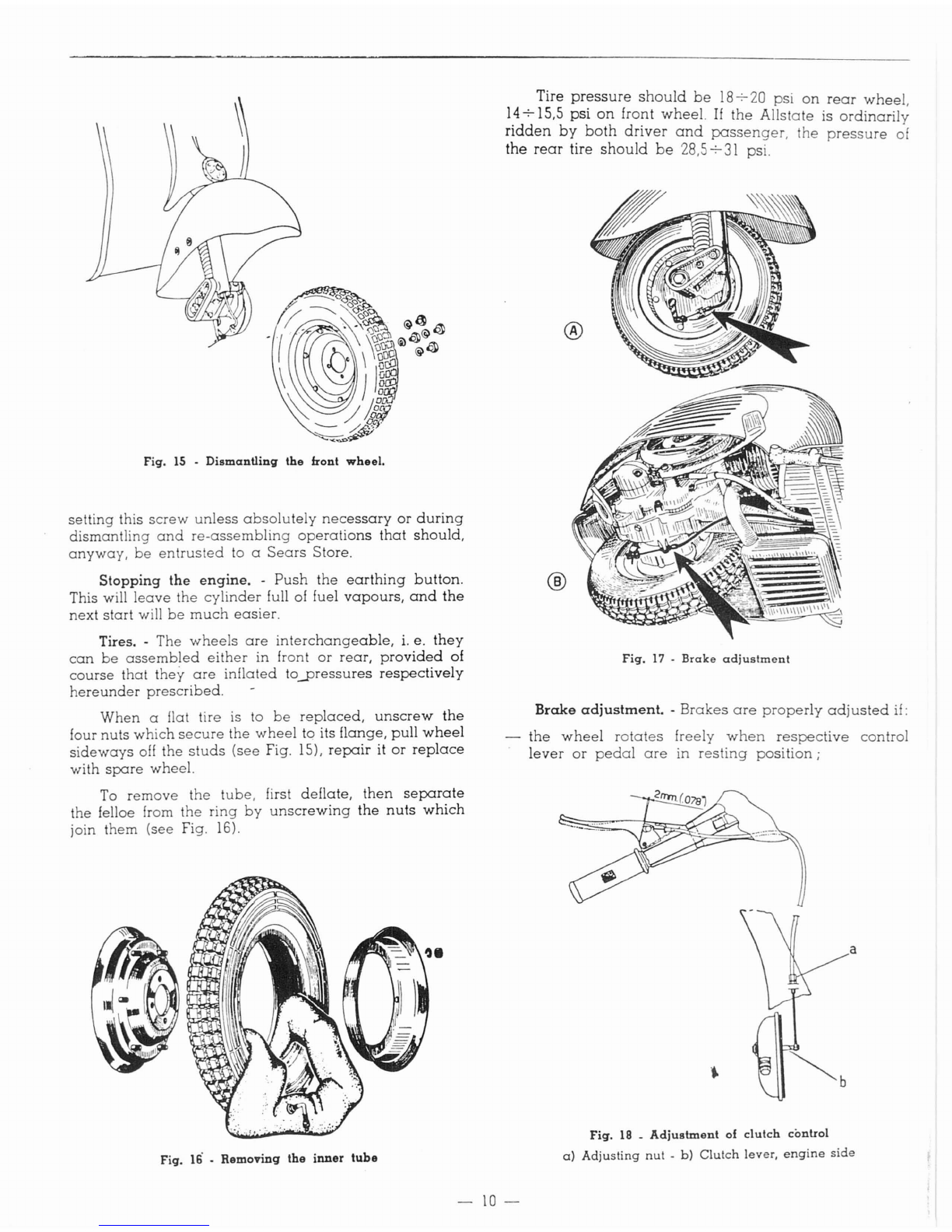
Fig.
15
-
Dismantling
the
front
wheel.
setting this
screw
unless
absolutely
necessary
or
during
dismantling
and
re-assembling
operations
that
should,
anyway,
be
entrusted
to a
Sears
Store.
Stopping
the
engine.
-
Push
the
earthing
button.
This will
leave
the
cylinder
full of fuel
vapours,
and
the
next
start
will
be
much
easier.
Tires. -The
wheels
are
interchangeable,
i.
e.
they
can
be
assembled
either
in front
or
rear,
provided
of
course
that
they
are
inflated
toyressures
respectively
hereunder
prescribed.
When
aflat tire is to
be
replaced,
unscrew
the
four
nuts
which
secure
the
wheel
to its flange,
pull
wheel
sideways
off
the
studs
(see
Fig. 15),
repair
it
or
replace
with
spare
wheel.
To
remove
the
tube,
first
deflate,
then
separate
the felloe from
the
ring
by
unscrewing
the
nuts
which
join
them
(see Fig. 16).
Fig.
16 -
Removing
the
inner
tube
Tire
pressure
should
be
18-;-.20
psi
on
rear
wheel,
14-;-'15,5
psi
on
front
wheel.
If
the
Allstate
is
ordinarily
ridden
by
both
driver
and
passenger,
the
pressure
of
the
rear
tire
should
be
28,5-;-'31 psi.
®
®
Fig.
17
-
Brake
adjustment
Brake
adjustment.
-
Brakes
are
properly
adjusted
if:
the
wheel
rotates
freely
when
respective
control
lever
or
pedal
are
in
resting
position;
a
Fig.
18 _
Adjustment
of
clutch
control
a)
Adjusting
nut
-b)
Clutch
lever,
engine
side
-10-

-the
braking
action
starts
as
soon
as
respective
controls
are
operated.
These
conditions
are
achieved
adjusting
the
cables
by
means
of
screws
indicated
with
an
arrow
in
Fig.
17.
Adjustment
of
clutch
control. -
Adjustment
of
clutch
controls is
achieved
operating
on
adjusting
nut
(a),
screwed
to the
engine
bracket
(see
Fig.
IB).
by
means
of
open
end
wrench
82199
in
the
tool roll.
The
cable
is to
be
tensioned
or
loosened,
as
the
case
may
be
so
that
control
lever,
on
handlebars,
makes
a
stroke
of 2mm.
(O.07B")
before
lever
(b).
on
engine,
starts
moving.
Wrong
play
in
the
control
may
cause
the
clutch
plates
burning
out
even
in
normal
riding
conditions.
MAINTENANCE
Every
5.000
miles:
In
case
of
shock-absorber
troubles,
overhaul
or
simply
clean
the
assembly
and
change
oil.
These
operations
should
be
carried
out
by
your
SEARS store.
(B) -
Clean
the
muffler
and
decarbonize
the
engine
as
explained
hereunder.
Remove
the
muffler,
the
cooling
hood,
the
cylinder
head
and
the
cylinder
(see
Fig. 20).
Decarbonize
the
piston
crown
and
the
cylinder
ports
from
all
carbon
deposits.
Decar-
bonize
the
inner
side
of
the
cylinder
head.
Care-
fully
clear
the
cylinder
carbon
deposits.
Heat
the
exhaust
pipe
of
the
muffler
and
clean
it
either
by
scraping
internally
with
a
hooked
wire
or
blowing
air
through
from
the
other
orifice; in
both
cases
the
muffler
should
be
held
so
that
the
exhaust
pipe
is
turned
downwards.
Clean
the
breaker
points.
In
order
to
avoid
ignition
troubles
or
abnormal
running,
have
the
breaker
points
adjusted
in a
use
Sears
stores;
the
gop
should
not
be
more
than
0.011 "-0.01
9"
(see
Fig.
19)
and
the
points
should
begin
to
open
when
the
current
in
the
primary
Ignition
d,cuH
has
allalned
ils
peak
value.
/
Fig.
l~
-
Breaker
points
•Max.
gap
of
breacker
points
should
be
a
all"
-D.OI
g"
(l)
-
-
11
-
Cleaning
the
scooter.
-
Brushing
kerosene
and
wiping
dry
with
clean
rags
is
advisable
for
external
cleaning
of
engine.
All JXlinted
surfaces
should
be
washed
with
water,
rinsed
by
means
of a
sponge
and
wiped
dry
with
a
chamois. Do
not
use
kerosene
on
such
surfaces,
since
it
damages
JXlint
and
turns
it dull.
II
necessary,
blow
the
head
lamp
reflector
clean
or
wipe
off
dust
with
a
very
soft feather. Do
not
use
a
cloth
and
keep
your
fingers off reflector
surface.
Before
setting
the
machine
in
motion,
(if
it
has
been
delivered
directly
to
the
customer
by
the
Factory)
check
oil level in
gear
box
by
unscrewing
from the
cranckase
the level
screw
marked
«OLIO»
(see
Fig. 21).
The
scooter
standing
upright,
oil
should
just
be
about
to
flow out.
After
the
first 600 miles. -
Replace
oil
in
the
gear
box
by
the
procedure
as
explained
in
the
lubrication
chart, JXlge
13.
The
crankcase
can
be
drained
through
the hole
indicated
in Fig.
21.
Every
2.500
miles:
(l)
-Remove
the
air
cleaner
from the
carburettor
and
wash
it in a
30
'Yo
gasoline-oil
bath.
(2) -
Check
oil level in
the
gear
box
(see
above).
(3) -
Grease
all joints
on
the
brake
controls.
(4) -
Clean
the sJXlrkplug
electrodes
with
very
fine
emery
cloth
or
suitable
files,
and
adjust
the
gap
to
0.6
mm. (0.023").
Inspect
the
insulation
material
of
sJXlrkplug; re-
place
the
latter
if
the
porcelain
is
cracked.
Wash
with
neat
gasoline.
Use the sJXlrkplug
type
Marelli
CW
230
A-
T;
Marelli
CW
225
N-T;
Morelli
CW
225
A-T;
Bosch
W
225
Tl;
Champion
L.
86;
AC
43
F;
KLG F
70
or
F
75.
Important:
using
the
proper
type
o[
sparkplug
will
eliminate
many
engine
troubles.
(5)
-
Grease
the felt
which
lubricates
the
cam
of
fly-
wheel
magneto.
(6)
-
Clean
the
two
lubricators
on
front
wheel
hub
and
refil
them
by
means
of a
grease
gun.
N.B.
-All
operations
indicated
hereunder
should
be
carried
out
by
aSEARS
store.
(7)
-
Lubricate
the
speedometer
drive
pinion
and
flex
drive
(if
mounted).
(2)
-
Grease
the control
cables.
(3) -
Change
the oil in
the
gear
box,
as
stated
on
IXIge
13.
(4)
-
Grease
the
ratchet
quadrant
of
the
gear
shifter.
Disuse:
(l)
-
In
such
a
case,
cleaning
the
scooter
throughly
is
advisable.
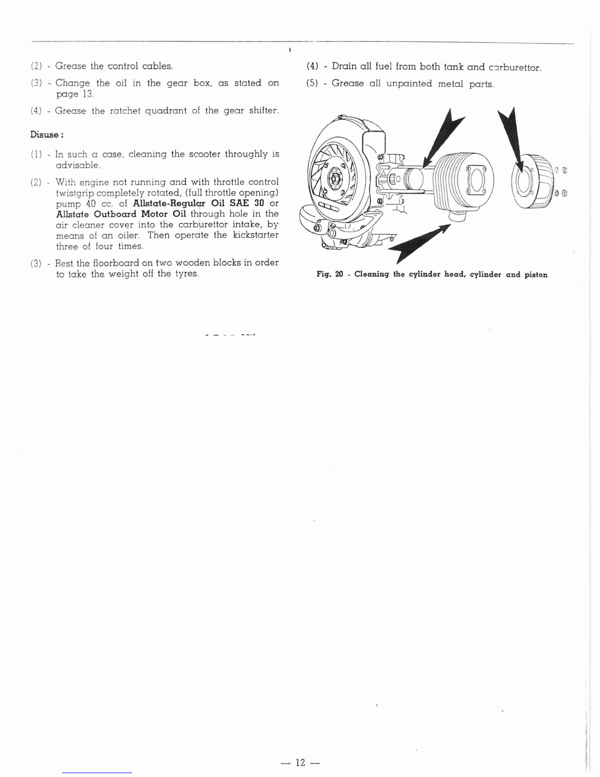
(2)
-With
engine
not
running
and
with throttle control
twistgrip
completely
rotated,
(full throttle
opening)
pump
40 cc. of Allstate-Regulca Oil SAE
30
or
Allstate Outboard Motor Oil
th~ough
hole in
the
air
cleaner
cover
into
the
carburettor
intake,
by
means
of
an
oiler.
Then
operate
the
kickstarter
three
of
four times.
(3)
-Rest the
floorboard
on
two
wooden
blocks
in
order
to
take
the
weight
off
the
tyres.
(4) -
Drain
all
fuel from
both
tank
and
clrburettor.
(5) -
Grease
all
unpainted
metal
parts.
~::
Fig.
20
.
Cleaning
the cylinder
head.
cylinder
and
piston
-
12-
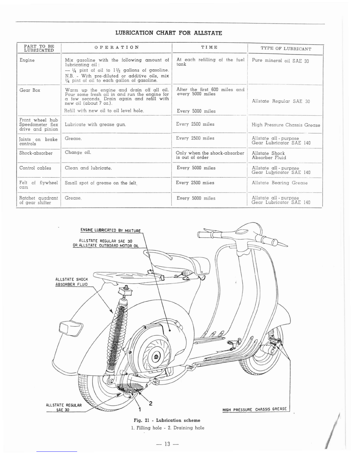
LUBRICATION
CHART
FOR
ALLSTATE
PART
TO
BE
OPERATION
TI
ME
I
TYPE
OF
LUBRICANT
LUBRICATED
Engine
Mix
gasoline
with
the
following
amount
of
At
each
refilling of
the
fuel I
Pure
mineral
oil SAE
30
lubricating
oil:
tank
-
'/4
pint
of
oil to
l'h
gallons
of
gasoline.
N.B.
-
With
pre-diluted
or
additive
oils, mix I
I
'/4
pint
of
oil to
each
gallon
of
gasoline.
I
----------
Gear
Box
Warm
up
the
engine
and
drain
oll
all
oil. After
the
first 600
miles
and
Pour
some
fresh oil in
and
run
the
engine
for
every
5000
miles
I
afew
seconds.
Drain
again
and
refill
with
Allstate
Regular
SAE
new
oil
(about
7oz.).
30
Refill
wi
h
new
oil to oil
level
hole.
Every
5000
miles
-
Front
wheel
hub
Speedometer
flex
Lubricate
with
grease
gun.
Every
2500
miles
High
Pressure
Chassis
Grease
drive
and
pinion
-
---
Joints
on
brake
Grease.
Every
2500
miles
Allstate
all
-
purpose
controls I
Gear
Lubricator
SAE
140
Shock-absorber
Change
oil.
Only
when
the
shock-absorber
Allstate
Shock
is
out
of
order
Absorber
Fluid
Control
cables
Clean
and
lubricate.
Every
5000
miles
Allstate
all
-
purpose
Gear
LUQricator SAE
140
--
Felt of flywheel
Small
spot
of
grease
on
the
felt.
Every
2500
miies
Allstate
Bearing
Grease
cam
Ratchet
quadrant
Grease.
Every
5000
miles
Ails a e
all
-
purpose
of
gear
shifter
Gear
Lubricator
SAE
140
EN6NE
LUBRICATED
BY
MIXTURE
ALLSTATE
REGULAR
SAE
30
OR
ALLSTATE
OUTBOARD
MOTOR
OIL
ALLSTATE
SHOCK
ABSORBER
FLUID
2
Fig.
21
-
Lubrication
scheme
1.
Filling
hole
-
2.
Draining
hole
-
13-
HIGH
PRESSURE
CHASSIS
GREASE

LOCATING
TROUBLES
AND RUNNING IRREGULARITIES
Carry
out
following checks
when
the
engine
does
not
start
easily
or
rWlS
irregularly.
Remedies
Locating
the
trouble
I'
1----=----------
------------
Locating
the
trouble
---
----------------
I
Remedies
-
--------------
I
--
DIFFICULT
STARTING
3,
-
Ignition
Sparkplug
dirty
Choke
flap
sticking
in
position
«
closed.
Replace
Replace
both
plates
and
springs
Replace
the
selector
Replace
the
pinions
Should
the
control
have
exces-
sive
play
in
neutral,
tension
control
cables
by
screwing
back
the
respective
adjuster
screw
(on
cable
sheath
end,
ratchet
quadrant
side)
with
an
8
mm
open
ended
wrench.
If
the
cable
tension
in
neutral
is
correct
but
the
reference
marks
of
the
handlebars
do
not
tally,
tighten
one
of
the
adjuster
screw
and
unscrew
the
other
one
to
the
same
extent,
so
that
the
cable
ten-
sion
is
not
altered.
feeble
I
Replace
4.
-Clutclh
troubles
a)
Clutch
snatches:
Gear
pinions
not
lubricated
Top
up
oil
level.
Tighten
the
properly
screw
on
draining
hole
b)
Clutch
slips:
Springs
feeble
Plates
worn
or
burnt
c)
Clutch
does
not
disengage
completely:
Excessive
play
on
control
Adjust
(see
fig.
18)
cable
5.
-
Gear
pinions
disengage
of i
own
accord
I
Gear
change
control
cables
out
Adjust
of
adjustment
Spring
of
stirrup
broken,
or
missing
Selector
arms
chamfered
Dogs
of
gear
pinions
chipped
or
worn
Turn
to «
reserve
"Refill
as
soon
as
possible.
Remove
and
wash
in
gasoline
-
Blow
dry
Correct
(see
fig. 19)
Replace
the
plug
Clean
with
suitable
files
or
very
fine
emery
paper
Release
Disconnect
the
plug
lead.
Check
if
sparking
occurs
between
lead
and
crankase
when
the
kicks
tarter
is
operated.
Clean.
Correct
gap
to 0.6 mm.
I
(023")
I
I
See
page
8
I
I
Replace
Clean
(see
page
II)
Clogged
dirty
Porcelain
of
sparkplug
cracked
Breaker
points
dirty,
partially
worn
or
pitted
Gap
between
breaker
points
in-
correct
Engine
flooding
Float
perforated
Air
cleaner
choked
or
dirty
2.
-
Carburation
1.
-
ruel
system
Fuel
tank
empty
Filter
on
carburettor
(
Fuel
tap
body
Carburet
tor
body
Main
jet
\.
Atomizer
Packing
of fuel
tap
I
INCORRECT
RUNNING
Not
enough
mixture
flowing
to
See
paragraph
cDifficult
start-
the
carburettor
ing.,
No. 1
Breaker
points
completely
worn
Replace
or
pitted
i
Timing
wrong
I
Re-time
ignition
1.
-
Lack
of
power
I
Muffler
outlet
pipe
carbonized
I
Clean
(see
page
11)
Exhaust
port
partially
closed
by
,
Decarbonize
cylinder,
piston
and
carbon
deposit
cyhnder
head
Cylinder
base
gasket
not
sealing
Replace
Adjust
(see
Fig.
17)
Wash
with
gasoline
or
replace
Replace
Dismount
and
clean
carburettor
in
gasoline
and
compressed
air.
For
type
and
diameter
of
jets
and
vents,
see
page
5.
Replace
Re-time
See
No. 2of
this
paragraph
Replace
Clean
with
pure
gasoline
and
blow
dry.
Dip
the
metal
wad-
ding
into
a
30'10
gasoline-oil
bath
Lubricate
or,
if
necessary,
re-
place
Adjust
Slacken
Tighten
III
-Jets
or
air
vents
of
the
car-
buret
tor
blocked
or
dirty;
incorrect
or
increased
dia-
meter
IV
Retarded
ignition
V -
Poor
compression.
7
..
Controls
not
operating
pro-
perly
Inner
cables
rusted
6.
-
High
fuel
consumption
I -
Fuel
level
too
high
in
car-
burettor:
Float
perforated
iI
-Air
cleaner
chocked
or
dirty
Excessi
ve
play
8.
-
Steering
column
becomes
stili
Top
race
of
top
ball
bearing
too
tight
Bottom
races
of
the
two
bear-
ings
pitted
9. -
Excessive
play
of
steering
column
Top
race
of
top
bearing
loose
10. -
Poor
braking
Stroke
of
pedal
or
lever
too
long
Brake
linings
oily
or
worn
down
Brake
drums
and
linings
scrat-
ched
a)
Fit
on
a
proper
type
of
spark-
plug
b)
Re-time
the
ignition
Replace
Tighten
Replace
or
clean
the
plug
and
correct
the
gap
to 0.6
mm
(.023")
Clean
Tip of
contact
breaker
loose
Condenser
screw
loose
Pre·ignition
Sparking
plug
carbon-coated
or
with
excessive
electrode
gap
Carbon
pearls
on
sparkplug
in-
sulation
2.
-
Poor
compression
I
Sparkplug
not
well
screwed
Tighten
(21
mm
box
wrench)
down
in
cylinder
head
Cylinder
head
not
fitting
properly
I
Set
the
head
properly
and
tigh-
into
the
spigot
on
top
of
cy-
ten
the
nuts
linder
Piston
rings
gummed
up
I
Clean
the
rings
and
grooves
3.
-
Explosions
at
muller
or
car-
bureltor
-
..
-
14
--

PARTS
LIST
TABLE I
©
~
&\~44
/"',
@2040
S.1~7
5.3t
\
~
s.J057 \ -
46684
26278
87584
87GS5
26rS
~9290
I</~J~
~
:~~,
4661
87422
87423
89671
S.14441
~\~~.
~
~'8
92230
@
PARTS
UST
FOR
ENGINE
Crankcase
-
Cylinder
(TABLE
I)
Part
Number
Table
Section
DESCRIPTION
Part
Number
Table
Section
DESCRIPTION
I
318 D
Gasket,
copper,
of
sparkplug
2/84821 A
Hood,
cooling
2040 C
Adjuster
of clutch 84644 B
SeaL
spring
loaded,
[or
crankcase,
2444 CNut
flywheel
side
86944
B
Piston,
with
standard
wr'st
pin
(with
13903 D
Sparkplug,
with
gasket
2/51992 -
S.
6615)
23823 C
Adjuster
of
rear
brake
87420
B
Piston,
1st
oversize,
with wrist
pin
26278 B
Ball
bearing,
of
crankshaft
(with
2/51992 -
S.
6615)
46261
A-B
Stud,
long,
cylinder
fastening
87421
B
Piston,
2nd
oversize
with wrist
pin
(with
2/51992
-
S.
6615)
46684 CBolt,
securing
crankcase
halves
Piston,
3rd
oversize
with wrist pin
87422
B
46741
D
Cap,
rubber,
for
sparkplug
(with
2/51992
-
S.
6615)
45290 B
Seal,
spring
loaded,
for
crankcase,
87423
B
Piston,
4th
oversize
with wrist pin
clutch
side
(with
2/51992
-
S.
6615)
49502 B
Gasket,
crankcase
8743'2
A
Ring,
piston,
1st
oversize
2/51992 A
Wrist
pin
87433 A
Ring,
piston,
2nd
oversize
52575 ARing, piston,
normal
87434 A
Ring,
piston,
3rd·
~versize
52625 A
Cylinder
-
15
--

Parts
list for
engine
-
Crankcase
-
Cylinder
-
Continued
Part
Number
Table
Section
DESCRIPTION
Part
Number
Table
Section
DESCRIPTION
II
87425 ARing. piston, 4th
oversize
I
IS.
5'21
B
Stud.
for fixing
carburettor
87436 D
Wrist
pin,
1st
oversize
S. 1107 A-B-C
Nut.
for
locking
cylinder
head
and
87437 DI
Wrist
pin,
2nd
oversize
crankcase
halves
87584
B
Crankcase
halves
(Parts
n. 12869 -S. 1207 C
Nut
40313 -40316 -
4626,1
-
46'6-31
-S. 1447 IC
46684 -47160 -47161 -47944 -
Nut.
spacer,
hood
fixing
47945 -47946 -47947 47948 -S. 3057 A-B-C
Washer.
plain
48000 -48002 -48035 -49502 -
51255 -54071 -81842 -a2086 -S. 2107 A-B-C-D
Washer.
spring
87685 -S.
521
-S. 1107 -S. 3057
S.6615
C
Circlip.
for
locking
wrist
pin
-S. 3107 -S. 10790 -S. 11288 -
S. 12485)
S.6977
A-C
Washer.
spring
87685 B
Plug.
on
crankcase,
flywheel
side
S.11288
A
Stud.
securing
crankcase
halves
89120 A
Gasket.
cylinder
base
S.
1'2485
BBolt.
short,
securing
crankcase
89871
D.
Engine.
g.
a.
halves
92230 D
Head,
cylinder
S.14441 D
Screw.
hood
fixing
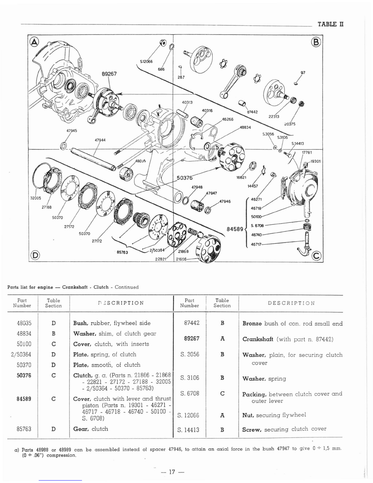
PARTS
UST
FOR
ENGINE
Crankshaft
-
Clutch
(TABLE II)
Washer
spring,
for
castle
nut
se-
curing
clutch
a)
47946
Part'
Number
97
267
686
14457
16821
17781
19301
2G375
21866
21868
22313
22821
27172
Table
Section
B
B
A
C
C
C
C
B
D
D
B
D
D
DESCRIPTION
Key. woodruff. for
crankshaft
(clutch
side)
Key. woodruff, for
crankshaft
(flywheel
side)
Washer.
shake
proal. for
nut
secur-
ing
flywheel
Spring,
for fixing
clutch
centralizing
plate
Plate.
clutch
centralizing
Gasket.
between
clutch
cover
and
crankcase
Breather.
with
inserts
Nut.
castle,
for
securing
clutch
Body
clutch
Cup,
clutch
spring
Spring.
clutch
Plate.
clutch,
with
linings
Part
Number
27188
32005
40313
40316
46266
46271
46717
46718
46740
47944
47945
47947
47948
Table
Section
D
D
B
B
B
C
C
C
C
A
A
C
C
C
DESCRIPTION
Driving
disc,
external,
of
clutch
Ring.
elastic,
for
stopping
clutch
plates
Spindle.
hollow, for
hydraulic
shock-
absorber
Bush.
bottom,
rubber,
of
shock-
absorber
Circlip.
locking
spacer
Piston,
slo
ted
thrus
,of
clutch
Lever.
outer,
clutch
control
Lever.
inner,
clutch
control
Spring,
return,
of
outer
clutch
con-
trol
lever
Spindle.
hollow, for
engine
su-
spension
Spacer,
flywheel
side
Spacer.
clutch
side
Bush.
rubber,
clutch
side
Washer.
plain
-
16-
TABLE
n
@
Paris
lisl lor
engine
-
Crankshaft
-
Clulch
-
Continued
84589
@
Part
Number
Table
Section
r.'::SCRIPTION
Part
Number
Table
Section
DESCRIPTION
I
48G35
D
Bush.
rubber,
flywheel
side
8744:2
B
Bronze
bush
of
can.
rod
small
end
48834
B
Washer.
shim, of
clutch
gear
89267
A
Crankshaft
(with
part
n.
87442)
5'0100
C
Cover.
clutch,
with
inserts
2/50364
D
Plate.
spring,
of
clutch
S.
2056
B
Washer.
plain,
for
securing
clutch
50370
D
Plate.
smooth,
of
clutch
cover
S<l376
C
Clutch.
g.
a.
(Parts
n.
21866
-
21868
S.3106 B
Washer.
spring
-
22821
-
27172
-
27188
-
32005
-
2/503&1
-
50370
-
85763)
S.
6708
C
Packing.
between
clutch
cover
and
84589
C
Cover.
clutch
with
lever
and
thrust
outer
lever
piston
(Parts
n.
19301
-
46271
-
461717
-
46718
-
46·740
-
50100
-
S.
12066
A
Nut.
securing
flywheel
S.
(708)
85763
D
Gear.
clutch
S.14413 B
Screw.
securing
clutch
cover
a)
Parts
48988
or
48989
can
be
assembled
instead
of
spacer
47946, to
attain
an
axial
force
in
the
bush
47947 10
give
0
-;-
1,5
mm.
(0
+.06")
compression.
-
17
-

---------------------------------_
TABLE
ill
@
~~lny{§
~-----:::7/
....
----"'--1)-'O>-\
17'"
B201lS
~sr"'47
47'90
'.1376'
"'"'S
\
@
PARTS
LIST
FOR ENGINE
Gear
box
-Rear
wheel
flange
©
(TABLE
ill)
Part
Number
Table
Section
DESCRIPTION
Part
Number
Table
Section
DESCRIPTION
61
AClip,
spring,
for
brake
jaws
a)
20322 CIWasher,
shoulder
2nd
oversize
2021
AScrew, for joining
brake
drum
to (thickness: 2,35 mm. =0"
.09.2)
flange
a)
20323 CWasher,
shoulder
3rd
oversize
2,442
ANut. for
securing
wheel
(thickness: 2,50 mm. =0".098)
7563 Ball
bearing
of
mainshaft
a)
20324 C
Washer,
shoulder
4th
oversize
A(thickness:
2,&5
mm. =0".104)
7886 A
Pad
23831 A
Drum,
rear
brake
12869 BScrew, for
dust
cover
42043 BArm,
rear
brake
control
17821
DSelector,
gear
42047 BLink,
brake
18447
CCirclip,
retaining
shoulder
washer
42048 BPin, for
rear
brake
links
a)
18558
CWasher,
shoulder,
normaL of
gear
46605 CStem,
selector
pinions
Washer,
shoulder,
1st 46688 A
Ring,
locking
ball
bearing
a)
20321
C
oversize
(thickness: 2,2 mm. =0".086) 46699 A
Seal,
spring
-
loaded
of
mainshaft
a)
The
total
axial
play
01
the
assembly
01
the
3
gear
pinions
in
respect
to
their
seat
must
be
contained
between
.006"
and
.012".
Should
this
play
exceed
said
tolerances,
the
normal
shoulder
washer
must
be
replaced
by
another
with
proper
oversize.
10
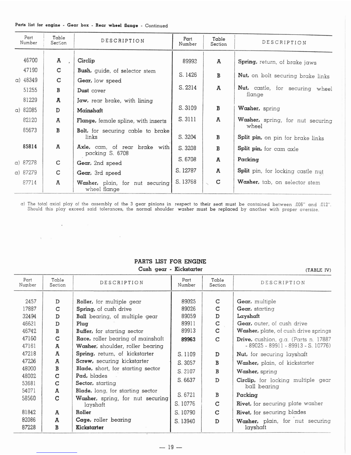
Parts list lor
engine
.
Gear
box
.
Rear
wheel
nange
-
Continued
Part
Number
46700
47190
a)
48349
51255
81229
a)
82085
82120
85073
858J.4
a)
87278
a)
87279
87714
Table
Sec:;on
A
C
C
B
A
D
A
B
A
C
C
A
DESCRIPTION
Circlip
Bush,
guide,
of selector
stem
Gear, low
speed
Dust
cover
Jaw,
rear
brake,
with lining
Mainshaft
Flange, female spline, with inserts
Bolt, for
securing
cable
to
brake
links
Axle,
cam,
of
rear
brake
with
packing
S.
6708
Gear, .2nd
speed
Gear,
3rd
speed
Washer, plain, for
nut
securing
wheel
flange
Part
Number
89993
S.
1426
S.2314
S.3109
S.3111
S.3204
S.3208
S.
6708
S.12787
S. 13768
Table
Section
A
B
A
B
A
B
B
A
A
C
DESCRIPTION
Spring,
return,
of
brake
jaws
Nut,
on
bolt
securing
brake
links
Nut, castle, for
securing
wheel
flange
Washer,
spring
Washer,
spring,
for
nut
securing
wheel
Split Pin.
on
pin
for
brake
links
Split pin, for
cam
axle
Packing
Split pin, for
locking
castle
nl.;!.t
Washer,
tab,
on
selector
stem
a) The total
axial
play
of
the
assembly
of
the
3
gear
pinions
in
respect
to
their
seat
must
be
contained
between
.006"
and
.012".
Should
this
play
exceed
said
tolerances,
the
normal
shoulder
washer
must
be
replaced
by
another
with
proper
oversize.
PARTS
LIST
FOR ENGINE
Cush
gear
-Kickstarter
(TABLE
IV)
Part
Nu~ber
Table
Section
DESCRIPTION
I
Part
Number
Table
Section
DESCRIPTION
2457
DRoller, for multiple
gear
89025 CGear, multiple
17887
CSpring,
of
cush'
drive
89026 CGear,
starting
32494
DBall
bearing,
of multiple
gear
89059 DLayshaft
46631
DPlug
89911
CGear,
outer,
of
cush
drive
467'42
B
BuHer,
for
starting
sector
89913 CWasher,
plate,
of
cush
drive
springs
4716D
CRace. roller
bearing
of
mainshaft
89963
CDrive,
cushion,
g.a.
(Parts n. 17887
47161
AWasher; shoulder, roller
bearing
-89025 -
89911
-89913 -
S.
10776)
47218
ASpring. return,
of
kickstarter S. 1109 DNut. for
securing
layshaft
47226
AScrew,
securing
kicks
tarter
S.3057
BWasher, plain, of kickstarter
48000
BBlade. short, for
starting
sector
S.
3107 BWasher,
spring
48002 CPad,
blades
S.61)37 Circlip. for locking multiple
53681
CSector.
starting
D
gear
ball
bearing
514071
ABlade. long, for
starting
sector
S.6721 BPacking
58560
CWasher. spring, for
nut
securing
layshaft
S.10776 CRivet. for
securing
plate
washer
81842
ARoller S. 10790 CRivet. for
securing
blades
82086
A
Cage,
roller
bearing
S. 13940 DIWasher. plain, for
nut
securing
87228
BKickstarter 1ayshaft
-
19-

47218-------8
.@
81842
/
47150
82086
co
47161
~"oo
~
~
53681
58560 5.6537
{
~/46631
89911
89025 v
89963
TABLE IV
@
__
87228
©
PARTS LIST
FOR
ENGINE
Flywheel
Magneto
-
Fan
Part
Table
DESCRIPTION
Part
Table
Number
Sec
ion
Number
Section
6G3
D
Screw,
for
securing
coils
16417
C
622
C
Washer,
shim, of
breaker
16418
C
624
C
Nut
16419
C
625
C
Fork
spring
16420
C
164'21
D
66.2
A-D
Terminal
46675
A
674
BCirc1ip, for flywheel
extraction
46750
D
2856
B
Screw,
long, for
securing
fan
cas-
46764
A
ing
cover
46766
A
2946
B
Screw,
short, for
securing
fan
cas-
-47191
A
ing
cover
47576
)
3213
C
Screw,
securing
condenser
and
felt B
blade
47577
B
6562
Washer,
plain,
of
cam
83125
D
B
83282
A
14501
A-D
Terminal
83386
D
16416
C
Breaker,
with
platinum
point
-
20-
(TABLE
V)
DESCRIPTION
Axle,
breaker
Gusset,
contact
Ring,
insulating
Cam
Blade
felt,
with
inserts
Cam
Condenser
Cable,
earth,
with
terminal
Grommet
FlywheeL
with
inserts
(Parts
n.
6562
-
46675
-
S.
10775)
Fan
Cover,
fan
casing
Stator
Link
CoiL
low
tension,
No. 1
Table of contents
Other Allstate Scooter manuals


