Allstate 788.94492 Use and care manual

OPERATING
INSTRUCTIONS
AND
PARTS
LIST
FOR
MOTOR SCOOTER
MODEL
NUMBER 788.94492
--,
This is
the
Model
Number
of
your
Allstate Motor Scooter. It will
be
found
on
a
plate
fastened
on
the
outside
of
the
hinged
door
under
the
seat. Always
mention
this
number
when
communicating
with
us regarding
the
Scooter,
or
when
ordering
repair
parts.
,..---
HOW
TO ORDER REPAIR PARTS
All
parts
listed herein
may
be
ordered
through
any
Sears
retail
or
mail
order
store. In ordering
parts
by
mail from
the
mail
order
store
which
serves
the
territory
in
which
you live, Selling Prices
will
be
furnished
on
request
or
parts
will
be
shipped
at
prevailing prices
and
you will
be
billed accordingly.
WHEN
ORDERING REPAIR PARTS, ALWAYS GIVE
THE
FOLLOWING INFORMATION:
1.
The
Part
Number
in this List.
2.
The
Part
Name
in this List.
3.
The
Model
Number
of
the
item.
This list is valuable. It will
assure
your
being
able to
obtain
proper
parts
service
at
all times.
We
suggest you
keep
it
with
other
valuable papers.
SEARS, ROEBUCK
AND
CO.
Scooterworks
USA
5410
Damen
Ave
Chicago IL 60625
888-96-VESPA
\\W\\'
.scoote
1'\\'01'
ks.
COI11

';
OPERATING
INSTRUCTIONS
AND
PARTS
LIST
FOR
'.
HOW
TO
ORDER
REPAIR
PARTS
MOTOR
SCOOTER,
wHEN
ORDERING REPAIR PARTS. ALWAYS GIVE THE
FOL-
LOWING
INFORMA
nON:
1.
-
The
Part
Number
in
this
List.
2. -
The
Part
Name
in
this List.
S
3.
-
The
Mo~e\,Number
of
the
item
.
r-----~MODEL
NUMBER
788.94492------,
"
This
is
th;;
Model
Number
of
your
Allstate
Motor
sc~'
er.
It
will
be
found
on
a
plate
fastened
on
the
outside
of
the
hing,
door
under
the
seat.
Always
mention
this
number
when
comm
'cating
with
us'regarding
the
Scooter.
or
when
ordering
parts.
~
"'"r'"
:
'I
!
',-'
/
~ll:~~.
~',AIi
parts
listed
herein
may
be
ordered
thr'ough
al'ly
Sears
retail
or
',I~'
'mqu
order
store.
In
ordering
parts
by
mail
from
the
mail
order
store
.
~',:.
w~ch
serves
the
territory
in
which
you
live.
Selling
Prices
will
be
..
.
ftIhushed
on
request
or
parts
will
be
shipped
at
,prevailing
prices
and
you
will
be
billed
accordingly.
'..
'I
".
/
..
"
.,
.
"'J~
I
..-'
...
.
):
~
.
This
list
is
valuable.
It
will
assure
,your
being
able
to
obtain
proper
parts
service
at
all
times.
We
suggest
you
keep
it
with
other
valuable
papers.
SEARS,
ROEBUCK
AND co.
'.

,
./
,I
Location
01
serial
Number
Fig. 1 -
ALLSTATE"
Cruisaire
•Motor
Scooter
WARNING
-2-
In
order
to
keep
your
ALLSTATE
Scooter
in
per-
fect
running
condition
and
not
to
void
the
guarantee,
always
have
your
machine
repaired
at
a
Sears,
Roe-
buck
and
Co. Store.
Special
care
should
be
taken
in
regard
to
the
fuel
mixture
which
should
be
regular
gasoline
and
oil of
the
make,
grade
and
in
the
amount
prescribed
in
this booklet.
Ethyl
gasoline
should
never
be
used.
Do
not
use
Allstate
compounded
motor
oil
or
other
Premium
Heavy
Duty
Motor
Oil
with
deter-
gents.
The
inexperienced
operator
should
exercise
caution
in
applying
front
wheel
brake,
to
avoid
locking.

THROTTLE
CONTROL
GRIP
FILLING
CAP
CHOKE
KICKSTARTER
FUEL
COCK
SHUTIER
OF
CAAME
SWITCH,
HORN
BUTTON.
EARTH
CONTACT
GEAR
SHIFT-CLUTCH
CONTROL
HORN
,,
..
'--
REAR
BRAKE
PEDAL
FRONT
BRAKE
LEVER
Fig.
2 -
Controls
of
Allstate
Scooter
MAIN
SPECIFICATIONS
Frame.
-Of
pressed
and
spot-welded
steel
sheet,
with
stream-lined
monocoque-type
structure.
Suspension.
-
Front
wheel:
coil
spring.
Rear
wheel:
coil
spring
and
coaxial
hydraulic
shock
absorber.
Engine.
-Two-stroke, flat
cast
iron
cylinder
and
cast
aluminum
alloy
cylinder
head.
Fuel
conSUmption:
(Gasoline
-oil
mixture)
Max.
speed
Wheelbase
.
Max.
width
on
handlebars
Max.
length
of
the
'scooter
.
Max.
height
Ground
clearance
Turning
circle.
.
Weight
(unladen)
Displacement.
Bore
....
Stroke . . .
Effective
power
at
5000
rpm
Compression
ratio
.
.118
miles
per
gal.
46.6
m.p.h.
45.6 in.
31
in.
66
in.
37
in.
8.6
in.
59
in.
189 Ibs.
1'23.67
cc. (7.48 cu.
in.)
S4
mm. (2.12 in.)
54
mm. (2.12 in.)
4.5 HP.
6.5:
1
Transmission.
-
Directly
from
engine
to
rear
wheel
through
clutch,
cushion
drive
and
gear
box
.
Starting.
-By
means
of
kickstarter,
right
hand
side
of scooter.
Gear
box.
-
3-speed
drive
with
mesh
gears
in
oil
bath:
Its
two-cable
control
is
coupled
with
that
of
the
clutch,
on
left
hand
side
of
handlebars.
Clutch. -
Wet
type;
steel
plates
with
cork
inserts.
Ignition. -By
flywheel
magneto.
Lighting
and
hom.
-By
flywheel
magneto,
teeding
both
head
lamp
(two-beam).
tail
lamp,
horn
and
stop
light.
Brakes. -
EXPanding
type.
Front
brake:
control
lever
on
right
hand
side
of
handlebars.
Rear
brake:
control
pedal
on
right
hand
side
of
floorboard.
Wheels.
-Of
pressed
steel
sheet,
interchangeable
and
easily
removable.
since
they
are
assembled
in
an
automobile-like
system.
Tires:
dia.
3.50 X8in.
Fuel
tank. -
Total
capacity:
2.17
gals.;
Reserve:
0.4 gals.;
Three-way
cock:
copen,.
- c
closed»
-
"reserve,.
-3-
_~
...
,~
_1
..
__
OPEN
SPEEDOMETER
HOUSING
/
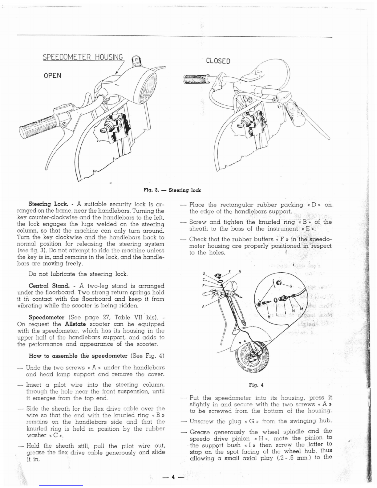
Fig. 3. -
Steering
lock
CLOSED
Steering
Lock. - A
suitable
security
lock is
ar-
ranged
on
the frame,
near
the
handlebars.
Turning
the
key counter-clockwise
and
the
handlebars
to
the
left,
the lock
engages
the
lugs
welded
on
the
steering
column,
so
that
the
machine
can
only
turn
around.
Turn the
key
clockwise
and
the
handlebars
back
to
normal position for
releasing
the
steering
system
(see
fig.
3). Do
not
attempt
to
ride
the
machine
unless
the key is in,
and
remains
in
the
lock,
and
the
handle-
bars
are
moving
freely.
Do
not
lubricate
the
steering
lock.
Central
Stand.
- A
two-leg
stand
is
arranged
under
the floorboard.
Two
strong
return
springs
hold
it
in
contact
with
the
floorboard
and
keep
it from
vibrating
while
the
scooter
is
being
ridden.
Speedometer
(See
page
27,
Table
VII
bis). -
On
request
the
Allstate
scooter
can
be
equipped
"With
the
speedometer,
which
has
its
housing
in
the
upper
half of the
handlebars
support,
and
adds
to
the
performance
and
appearance
of
the
scooter.
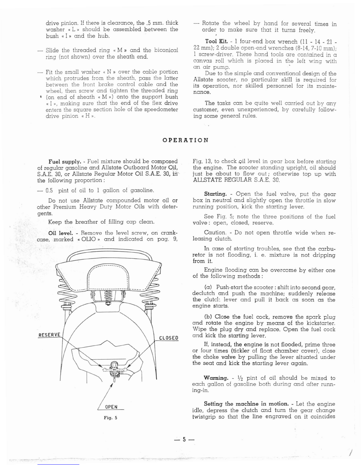
How
to
assemble
the
speedometer
(See Fig.
4)
-Undo the two
screws
«
A"
under
the
handlebars
and
head
lamp
support
and
remove
the
cover.
-Insert apilot
wire
into
the
steering
column,
through
the
hole
near
the
front
suspension,
until
it
emerges
from
the
top
end.
-Side the
sheath
for
the
flex
drive
cable
over
the
wire so
that
the
end
with
the
knurled
ring
«B»
remains
on
the
handlebars
side
and
that
the
knurled ring is
held
in
position
by
the
rubber
washer
«C
».
-Hold the
sheath
still,
pull
the
pilot
wire
out,
grease
the
flex
drive
cable
generously
and
slide
it in.
-
Place
the
rectangular
rubber
packing
«D"
on
the
edge
of
the
handl~bars
support.
-
Screw
and
tighten
the
knurled
ring
«B"
of
the
sheath
to
the
boss
of
the
instrument
«E".
-
Check
that
the
rubber
buffers
« F »
in
the
speedo-
meter
housing
are
properly
positioned
in
respect
to
the
holes. '
,.I
'J
Fig.
4
-
Put
the
speedometer
into
its
housing,
press
it
slightly in
and
secure
with
the
two
screws
«A,.
to
be
screwed
from
the
bottom
of
the
housing.
-
Unscrew
the
plug
«G»
from
the
swinging
hub.
-
Grease
generously
the
wheel
spindle
and
the
speedo
drive
pinion
«H
",
mate
the
pinion
to
the
support
bush
«I»
then
screw
the
latter
to
stop
on
the
spot
facing
of
the
wheel
hub,
thus
allowing
a
small
axial
play
(.2
-.6
mm.)
to
the
-4-
drive
pinion. If
there
is
clearance,
the
.5
mm. thick
washer
«L»
should
be
assembled
between
the
bush
«I»
and
the
hub.
-Slide the
threaded
ring
«M»
and
the
biconical
ring
(not
shown)
over
the
sheath
end.
-Fit the
small
washer
«N»
over
the
cable
portion
which
protrudes
from the
sheath,
pass
the
latter
between
the
fron
brake
control
cable
and
the
wheel,
then
screw
and
tighten
the
threaded
ring
,(on
end
of
sheath
«M")
onto
the
support
bush
«
1",
making
sure
that
the
end
of
the
flex
drive
enters
the
square
section
hole
of
the
speedometer
drive
pinion
«H
».
-
Rotate
the
wheel
by
hand
for
several
times
in
order
to
make
sure
that
it
turns
freely.
,
Tool Kit. -1
four-end
box
wrench
(11
-
14
-
21
-
22
mm); 2
double
open-end
wrenches
(8-14,
7-10
mm);
1
screw-driver.
These
hand
tools
are
contained
in a
canvas
roll
which
is
placed
in
the
left
wing
with
an
air
pump.
'
Due
to
the
simple
and
conventional
design
of
the
Allstate
scooter,
no
particular
skill is
required
for
its
operation,
nor
skilled
personnel
for its
mainte-
nance.
The
tasks
can
be
quite
well
carried
out
by
any
customer,
even
unexperienced,
by
carefully
follow-
ing
some
general
rules.
OPERATION
Fuel
supply.
-
Fuel
mixture
should
be
composed
of
regular
gasoline
and
Allstate
Outboard
Motor Oil,
S.A.E.
3D,
or
Allstate
Regular
Motor Oil S.A.E.
3D,
m"
the
following
proportion:
-
0.5
pint
of oil to 1
gallon
of
gasoline.
Do
not
use
Allstate
compounded
motor
oil
or
other
Premium
Heavy
Duty
Motor Oils
with
deter-
gents.
Keep
the
breather
of filling
cap
clean.
Oil level. -
Remove
the
level
screw,
on
crank-
case,
marked
«OUO»
and
indicated
on
pag.
9,
CLOSED
L
Fig.
5
Fig.
13,
to
check
.oil
level
in
gear
box
before
starting
the
engine.
The
scooter
standing
upright,
oil
should
just
be
about
to flow
out;
otherwise
top
up
with
ALLSTATE REGULAR S.A.E.
30.
Starting.
-
Open
the
fuel
valve,
put
the
gear
box
in
neutral
and
slightly
open
the
throttle in
slow
running
position, kick
the
starting
lever.
See
Fig.
5;
note
the
three
positions
of
the
fuel
valve:
open,
closed,
reserve.
Caution.
-Do
not
open
throttle
wide
when
re-
leasing
clutch.
In
case
of
starting
troubles,
see
that
the
carbu-
retor
is
not
flooding,
i.
e.
mixture
is
not
dripping
from it.
Engine
flooding
can
be
overcome
by
either
one
of
the
following
methods:
(a)
Push-start
the
scooter:
shift
into
second
gear,
declutch
and
push
the
machine;
suddenly
release
the
clute!:
lever
and
pull
it
back
as
soon
as
the
engine
starts.
(b)
Close
the
fuel
cock,
remove
the
spark
plug
and
rotate
the
engine
by
means
of
the
kickstarter.
Wipe
the
plug
dry
and
replace.
Open
the
fuel
cock
and
kick
the
starting
lever.
If,
instead,
the
engine
is
not
flooded,
prime
three
or
four
times
(tickler of
float
chamber
cover),
close
the
choke
valve
by
pulling
the
lever
situated
under
the
seat
and
kick
the
starting
lever
again.
Warning.
-
112
pint
of oil
should
be
mixed
to
each
gallon
of
gasoline
both
during
and
after
runn-
ing-in.
Setting
the
machine
in
motion.
-Let
the
engine
idle,
depress
the
clutch
and
tum
the
gear
change
twistgrip
so
that
the
line
engraved
on
it
coincides
-5-
.'
- - _
...
J
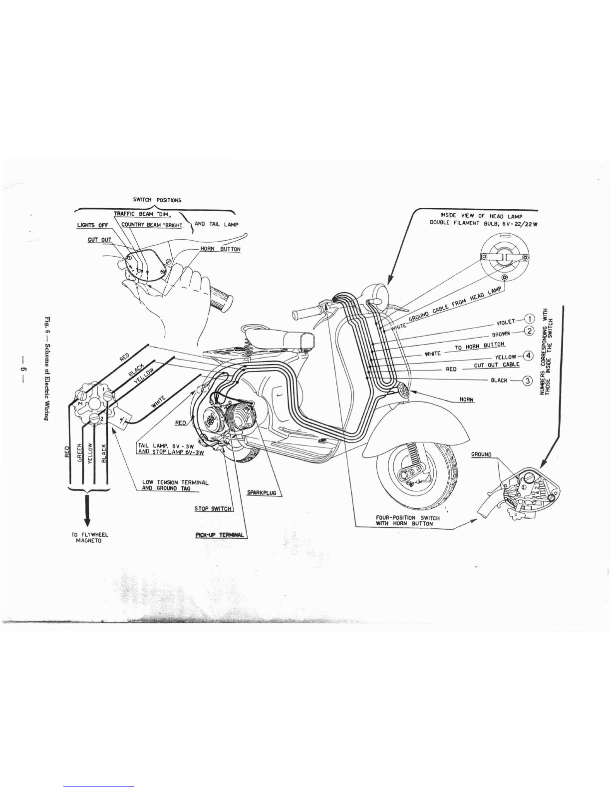
INSIDE
VIEW
OF"
HEAD
LAMP
DOUBLE
F"ILAMENT
BULB,
6V'
22/22W
HORN
BUTTON
LOW
TENSION
TERMINAL
AND
GROUND
TAG
CUT
OUT
SWITCH
POSITIONS
.-
..A...-~--~----_
,
TRAffiC
BEAM
"DIM
"\..
'
LIGHTS
orr
,\CO~TRY
BEAM
·B~IGH1.
)
AND
TAIL
LAMP
TO
F"LYWHEEL
MAGNETO
'--v--'
1
~
~
x
~\O\.E1-CD
~
~
1ix
~
u
BROWN-@
C)~
en
2~
I
en
BuTiQN f
....
n
'l'ELLOW-@
j:
l:l"
WHITE
Itil
B
til
CUT
OUT
CABLE
uQ
til
en
2-
RED
tIl~
I
!.'!l
BLACI<~
a:
........
til
~~
S:
z~
n
~
tl
lQ

with
the
number
1
(lst
gear)
engraved
on
handlebars
(see Fig. 7).
Now
let
in
the
clutch
gently,
while
open-
ing
the
throttle
gradually
to
set
the
machine
in
motion.
Gear
change.
-After
reaching
the
required
speed
in
1st
gear,
close
quickly
the
throttle,
depress
the
Fig.
7
clutch
and
tum
the
gear
change
twistgrip
so
that
the
engraved
line
is
opposite
number
2
(2nd
gear);
let
in
the
clutch
and
open
the
throttle
gradually.
Repeat
this
procedure
for
changing
into
3rd
gear.
For
changing
down,
close
the
throttle,
depress
the
clutch
and
tum
the
gear
change
twistgrip
to
the
required
position.
When
you
reduce
the
speed
of
your
machine,
change
down
with
no
delay.
Do
not
tum
the
gear
change
twistgrip
while
the
engine
is
not
running.
Fig.
8
As
soon
as
gear
change
troubles
arise,
parti-
,,1/
cularly
when
the
control
becomes
hard,
customers
should
have
their
machines
adjusted
at
a
Sears
Roebuck
and
Co.
store.
Tires. -
The
wheels
are
interchangeable,
i.
e.
they
can
be
assembled
either
in
front
or
rear,
pro-
vided
of
course
that
they
are
enflated
to
pressures
respectively
hereunder
prescribed.
When
aflat
tire
is
to
be
replaced,
unscrew
the
four
nuts
which
secure
the
wheel
to
its
flange,
pull
wheel
sideways
off
the
studs
(see
Fig. 8),
repair
it
or
replace
with
spare
wheel.
To
remove
the
tube,
deflate
it
first,
then
sepa-
rate
the
felloe from
the
ring
by
unscrewing
the
nuts
which
join
them
(see
Fig. 9).
Tire
pressure
should
be
18
psi
on
rear
wheel,
11
psi
on
front
wheel.
If
the
Allstate
is
ordinarily
ridden
by
both
driver
and
passenger,
the
pressure
of
the
rear
tire
should
be
28 psi.
Fig.
9
Stopping
the
engine.
-
Push
the
switch
lever
all
the
way
to
the
left;
fuel
vapors
remain
in
the
cylinder
in
this
way,
and
the
next
start
will
be
much
easier.
Brake
adjustment.
-
Brakes
are
properly
ad-
justed
if:
-
the
wheel
rotates
freely
when
respective
control
lever
or
pedal
are
in
resting
position;
-
the
braking
action
starts
as
soon
as
respective
controls
are
operated.
-7-
/

"T
CJutch
leyer:
~ine
side
BClutch lever
on
handlebars
Fig.
12
Wrong
play
in
the
control
may
cause
the
clutch
plates
burning
out
even
i.n
normal
riding
conditions.
The
cable
is
to
be
tensioned
or
loosened,
as
the
case
may
be,
so
that
control
lever
(B),
on
handle-
bars,
makes
a
stroke
of 2
mm.
(.078")
before
lever
(C),
on
engine,
starts
moving.
Adjustment
of
clutch
control.
-
Adjustment
of
clutch
control
is
achieved
operating
on
adjusting
nut
(A),
screwed
to
the
engine
braket
(see
Fig. 12),
by
means
of
open
end
wrench
15655
in
the
tool
roll.
Slow
running
adjustment.
-
No
hand
tool
is
re-
quired
for this
job;
idling
revs
can
be
raised
by
simply
tightening
the
screw
which
presses
on
car-
buretor
cover
and
vice-versa.
Fig.
10
c
Fig.
11
s::::>
sS~
a
tr
7
2
?5
'
~
~
ups,
\
I:;
~:
!
1I1i"!
I
~
sp
7
I:D
These
conditions
are
achieved
adjusting
the
cobles
by
means
of
screws
indicated
with
an
arrow
in Figs.
10
and
11.
-8-
MAINTEN
ANCE
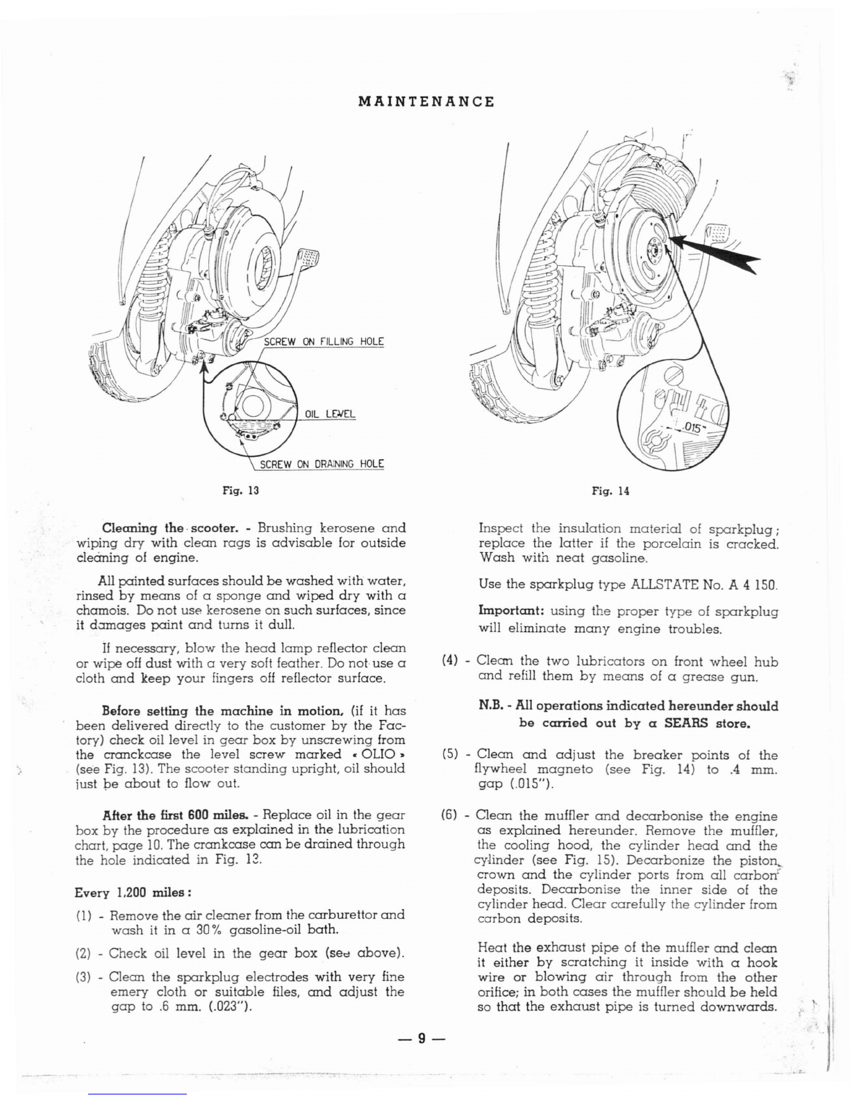
Fig.
13
Cleaning
the·
scooter.
-
Brushing
kerosene
and
wiping
dry
with
clean
rags
is
advisable
for
outside
cleaning
of
engine.
All
painted
surfaces
should
be
washed
with
water,
rinsed
by
means
of a
sponge
and
wiped
dry
with
a
chamois. Do
not
use
kerosene
on
such
surfaces,
since
it
d.:rrnages
paint
and
turns
it
dull.
If
necessary,
blow
the
head
lamp
reflector
clean
or
wipe
off
dust
with
a
very
soft feather. Do not·
use
a
cloth
and
keep
your
fingers
off
reflector
surface.
Before
setting
the
machine
in
motion,
(if
it
has
been
delivered
directly
to
the
customer
by
the
Fac-
tory)
check
oil
level
in
gear
box
by
unscrewing
from
the
cranckcase
the
level
screw
marked
•
OLIO
~
(see Fig.
13).
The
scooter
standing
upright,
oil
should
just
be
about
to flow out.
After
the
first
600
miles. -
Replace
oil in
the
gear
box
by
the
procedure
as
explained
in
the
lubrication
chart,
page
10.
The
crankcase
can
be
drained
through
the hole
indicated
in Fig.
12.
Every
1.200
miles:
(l)
-Remove
the
air
cleaner
from
the
carburettor
and
wash
it
in
a
301"0
gasoline-oil
bath.
(2) -
Check
oil
level
in
the
gear
box
(sec
above).
(3) -
Clean
the
sparkplug
electrodes
with
very
fine
emery
cloth
or
suitable
files,
and
adjust
the
gap
to
.6
mm. (.023").
Fig.
14
Inspect
the
insulation
material
of
sparkplug;
replace
the
latter
if
the
porcelain
is
cracked.
Wash
with
neat
gasoline.
Use
the
spark
plug
type
ALLSTATE No. A4150.
Important:
using
the
proper
type
of
sparkplug
will
eliminate
many
engine
troubles.
(4) -
Clean
the
two
lubricators
on
front
wheel
hub
and
refill
them
by
means
of a
grease
gun.
N.B.
-All
operations
indicated
hereunder
should
be
carried
out
by
aSEARS
store.
(5)
-
Clean
and
adjust
the
breaker
points
of
the
flywheel
magneto
(see
Fig.
14)
to
.4
mm.
gap
(.015").
(6) -
Clean
the
muffler
and
decarbonise
the
engine
as
explained
hereunder.
Remove
the
muffler,
the
cooling
hood,
the
cylinder
head
and
the
cylinder
(see
Fig. 15).
Decarbonize
the
piston~
crown
and
the
cylinder
ports
from
all
carbon!'
deposits.
Decarbonise
the
inner
side
of
the
cylinder
head.
Clear
carefully
the
cylinder
from
carbon
deposits.
Heat
the
exhaust
pipe
of
the
muffler
and
clean
it
either
by
scratching
it
inside
with
a
hook
wire
or
blowing
air
through
from
the
other
orifice;
in
both
cases
the
muffler
should
be
held
so
that
the
exhaust
pipe
is
turned
downwards.
-9-

-
----
.'~
Fig.
15
LUBRICATION CHART FOB
~ATE
PART
TO
BE
OPERATION
TIM
E
TYPE
OF
LUBRICANT
LUBRICATED
Engine
Mix
gasoline
with
the
following
amount
of At
each
refilling of
the
fuel
Allstate
Regular
SAE
30
or
lubricating
oil :
tank
Allstate
Outboard
Motor
Oil
-
0.5
pint
of oil to I
gallon
of
gasoline.
Gear
Box
W=
up
the
engine
and
drain
off
all
oil. After
the
first
600
miles
Pour
some
fresh
oil
in
and
run
the
engine
for afew
seconds.
Drain
again
and
refill
with
Allstate
Regular
SAE 30
new
oil
(see
page
9
and
Fig. 13).
Refill
with
new
oil to
011
level
hole.
Every
1200
miles
Front
wheel
hub
Lubricate
with
grease
gun.
Every
1200
miles
High
Pressure
::hassis
Grease
Joints
on
brake
controls
Grease.
Every
1200
miles
Allstate
all-purpose
Gear
Ratchet
quadrant
Lubricator
SAE
140
of
gear
shifter
Shock-absorber
Change
oil.
Only
when
the
shock-absorber
Allstate
Shock
is
out
of
order
Absorber
Fluid
Control
cables
Clean
and
lubricate.
Every
1800
miles
Allstate
all-purpose
Gear
Lubricator
SAE
140
Felt of fiywheel
Small
spot
of
grease
on
the
felt.
Every
1800
miles
Allstate
Bearing
Grease
cam
Every 1,800 miles. -
Grease
the
felt which
lubri-
cates
the
cam
of flywheel
magneto.
In
case
of
shock-absorber
troubles,
overhaul
or
simply
clean
the
assembly
and
change
oil.
These
operations
should
be
carried
out
by
your
SEARS store.
Disuse :
(1) -In
such
a
case,
cleaning
the
scooter
thoroughly
is
advisable.
(2)
-
Start
the
engine
and
run
it
at
low
revs
in
neutral.
Pump
60
cc. of
Allstate
Regular
Oil
SAE
"30
or
Allstate
Outboard
Motor
Oil
through
hole
in
the
air
cleaner
into
the
carburettor
intake,
by
means
of
an
oiler.
(3)
-Rest
the
floorboard
on
two
wooden
blocks
in
order
to
take
the
weight
off
the
lyres.
(4)
-
Drain
all
fuel from
both
tank
and
carburettor.
(5)
Grease
all
unpainted
metal
parts.
-10
-
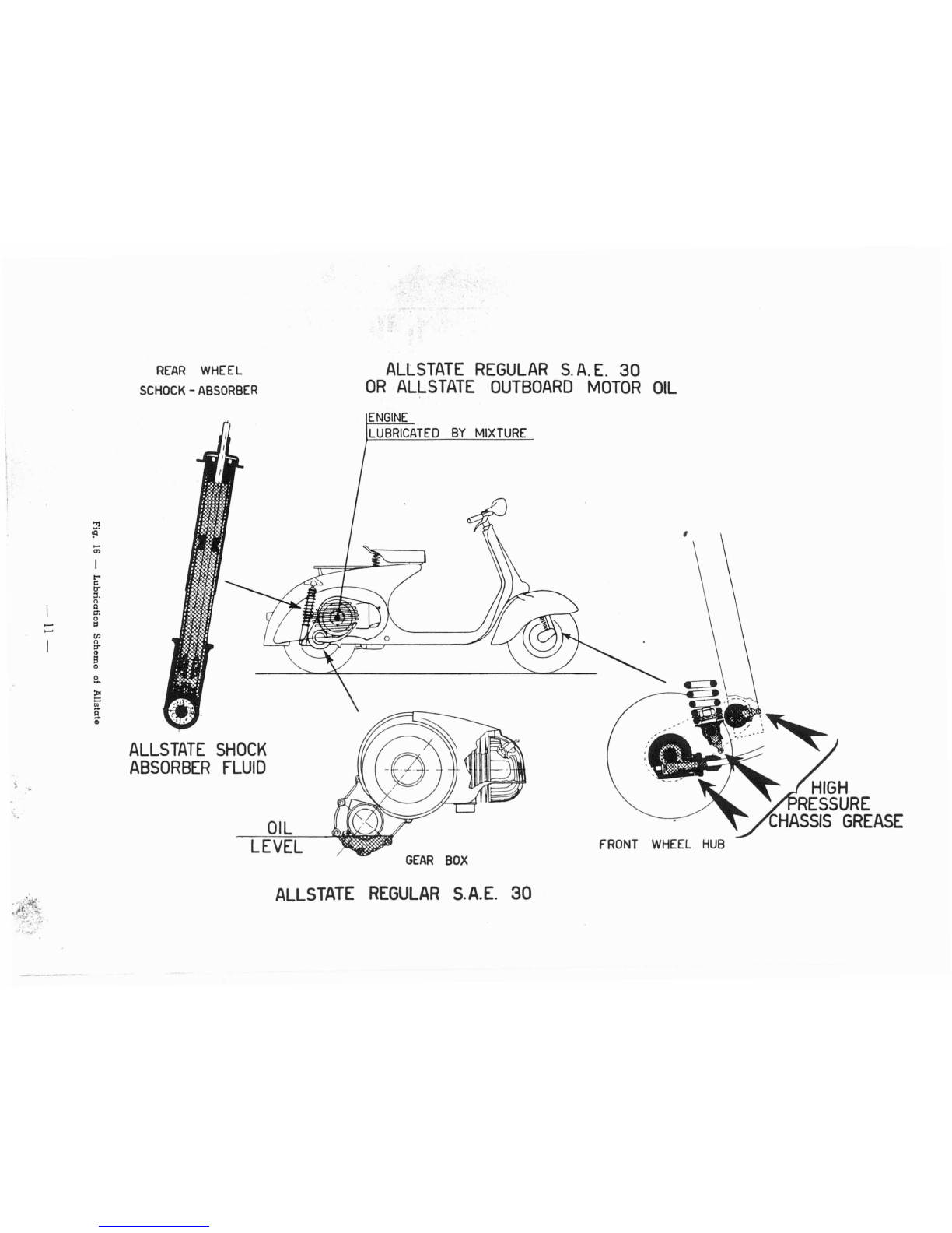
REAR
WHEEL
SCHOCK
-
ABSORBER
ALLSTATE
REGULAR
S.
A.
E.
30
OR
ALLSTATE
OUTBOARD
MOTOR
OIL
,
'.
,
<.
:!l
'f-l
....
m
t"'
~
tr'
::I.
n
I:l
1::".
.......
0
.......
I::l
til
n
:r
t)
B
CD
a.
~
in'
R
~
ALLSTATE
SHOCK
ABSORBER
FLUID
OIL
LEVEL
ENGINE
LUBRICATED
BY
MIXTURE
GEAR
BOX
fRONT
WHEEL
HUB
HIGH
RESSURE
CHASSIS
GREASE
:~.~~
.}
ALLSTATE
REGULAR
S.A.E.
30

LOCATING
TROUBLES
AND RUNNING IRREGULARITIES
Carry
out following checks
when
the
engine
does
not start easily
or
runs
irregularly.
~~
.-'
/..-'-
Adjust
(see
Figs.
10
and
11.
page
8).
Wash
with
gasoline
or
replace.
Replace
Replace
Tighten
Slacken
Lubricate
or,
if
necessary,
re-
place
Adjust
Re-time
See
No. 2of
this
paragraph
Fit
proper
jet
(.80 mm.)
Release
Clean
with
pure
gasoline
and
blow
dry,
Dip
the
metal
wadding
into
a39%
gaso-
line-oil
bath
" .
Release
operating
and
lubri-
cating
the
lever
on
the
bacl:
of
the
cleaner
case
Replace
Clean
or
replace
both
needle
and
float
chamber
cover
Replace
the
selector
Replace
the
pinions
Adjust
Replace
Replace
Replace
both
plates
and
springs
See
paragraph
•Difficult
start-
ing"
No. I
Turn
convex
face
towards
spring
cups.
Top
up
oil
level.
Tighten
the
screw
on
drainin
=1
hole.
Adjust
Tighten
the
screws
Replace
ReJ?~ace
.F
r-
,,~
Excessive
play
8
••
Steerinq
column
becomes
stili
Top
race
of
top
ball
bearing
too
tight
Bottom
races
of
the
two
bea-
rings
pitted
9
.•
Excessivo
play
of
steering
column
Top
race
of top
bearing
loose
10
••
Poor
bralring
Stroke
of
pedal
or
lever
too
long
Brake
linings
oily
or
worn
down
Brake
drums
and
linings
scrat-
ched
IV
-
Diameter
of
main
jet
ori-
fice
wrong
or
increased
V -
Retarded
ignition
VI
-
Poor
compression
7. -
Control.
not
operating
pro-
perly
Inner
cables
rusted
III
-
Flap
of
choke
valve
sticl:-
ing
in
closed
or
partially
closed
position
6
••
High
fuel
consumption
I -
Fuel
level
too
high
in
car-
burettor:
a)
Tickler
sticking
in
de-
pressed
position
bl
Float
perforated
c)
Float
needle
valve
not
properly
fitting
into
its
seating
II
-Air
cleaner
chol:ed
or
dirty
Not
enough
mixture
Dowing
to
the
carburettor
4.
•
Clutch
troubles
a)
Clutch
snatches:
Convex
steel
plates
wrongly
assembled
Gear
pinions
not
lubricated
properly
b)
Clutch
slips:
Springs
feeble
Plates
with
cork
-ii'lllerts
worn
or
burm
c)
Clutch
does
not
disengage
completely:
'
Excessive
play
on
conlrol
cable
Excessive
convexity
of
steel
plates.
S
••
Gear
pinions
disenllalle
of
own
accord
Gear
change
control
cables
out
of
adjustment
Gear
shifter
loose
on
crankcase
Spring
of
stirrup
broken,
feeble
or
missing
Excessive
play
between
ac-
tuating
arm
and
gear
shift
flange
or
wrong
positi?ning
of
the
arm.
Selector
arms
chamfered
Dogs
of
gear
pinions
chipped
or
worn
Tip of
contact
breaker
loose
Condenser
screw
loose
Clean
Replace
or
clean
the
plug
and
correct
the
gap
to 6mm.
(.023")
Replace
Clean
the
rings
and
grooves
Tighten
(21
mm
box
wrench)
Set
the
head
properly
and
tighten
the
nuts
Replace
Re-time
ignition
Replace
RUNNING
Clean
(see
page
9)
Replace
the
packing
between
pipe
and
cylinder.
Tighten
the
nuts
on
cylinder
studs.
Decarbonize
cylinder,
piston
and
cylinder
head
Replace
Disconnect
the
plug
lead.
Check
if
sparking
occurs
between
lead
and
crankcase
when
the
kicks
tarter
is
operated.
Clean.
Correct
gap
to
.6
mm.
(.023")
Replace
the
plug
Release
the
lever
Clean
with
suitable
files
or
very
fine
emery
paper
Correct
to
.4
mm.
with
feeler
gauge
(.015·)
Turn
to
vertical
position
Release
by
1lepressing
the
tickler
Replace
Clean
(see
page
9)
Release
Remove
and
wash
in
gasoline
-
Blow
dry
See
page
5
Release
Turn
to •
reserve..
Refill
as
soon
as
possible.
a)
Depress
the
tickler
until
some
fuel
drips
out,
or
b)
unscrew
and
remove
the
main
jet.
If
the
fuel
system
is
efficient, fuel
wil1
come
out.
c) Blow
trough
jet
orifice to
ensure
that
it
is
clean.
Clogged,
dirty
Locating
the
trouble
1
R_em_e_di_·e_s
II
Loc_ati_·n_
g
_t_h_e_lro_ub_I_8
1.
R_e_m_edi_'e_s
1
D
IFF
I C U L T S
TAR
TIN
GPre-i\1nition
a)
Fit
on
a
colder
sparkplug
b)
Re-time
the
ignition
Replace
Tighten
Exhaust port
partially
closed
by
carbon
deposit
Cylinder
base
gasket
not
tight
2.
-Poor
compression
Sparkplug
not
well
screwed
down
in
cylinder
head
Cylinder
head
not fitting
pro-
perly
into the
spigot
on
top
of
cylinder
Head
gasket
not light
Piston rings
gummed
up
3.
•Explosions
at
muffler
or
carburettor
Sparkinq
plug
carbon-coated
or
with
excessive
electrode
gap
Carbon
pearls
on
sparkplug
insulation
Breaker
points
completely
worn
or
pitted
Timing
wrong
Pick-up
terminal
cracked
INCORRECT
1.
-Lack
of
power
Muffler outlet
pipe
carbonized
Induction
pipe
to
cylinder
loose
Sparkplug
dirty
Porcelain
of
sparkplug
cracked
Switch
lever
jammed
in
•
cut
out.
position
Breaker
points dirty,
partially
worn or
pitted
Gap
between
breaker
points
incorrect
2.
-
Carburation
Enqine
flooding
Tickler sticking
in
depressed
position
Float
perforated
Air
cleaner
choked
or
dirty
Choke
flap sticking
in
position
•
closed.
Carburettor
assembly
mounted
at
an
angle
3. -Ignition
I. •
Fuel
syslem
Fuel
tank
empty
Fuel
does
not
Dow
10
the
car-
burettor
although
the
fuel
lap
is
open.
or
in
porq,ion
•
reserv"
-
Filter
on
carburettor
Fuel
tap
body
Carburettor
body
Main
jet
Atomizer
Hose
between
fuel
tap
and
carbu-
rettor
Float
needle
valve
sticking
on
its
seating
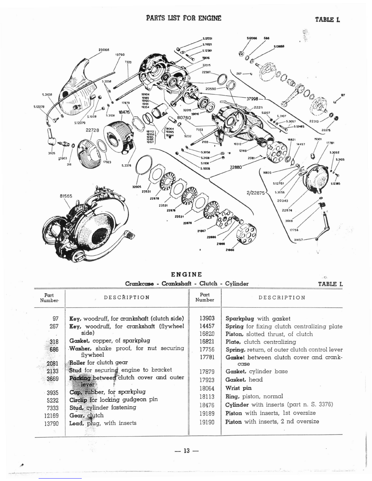
PARTS
UST
FOR
ENCIN£
TABLE
L
ENGINE
Crankccate •
Crankshaft
-
Clutch
-
Cylinder
TABLE
L
Part
DESC~IPTION
Part
DESCRIPTION
Number·
Number
97
Key, woodruff, for crankshaft (clutch side) 13903
Sparkplug
with
gasket
267 Key, woodruH, for crankshaft (flywheel 14457
Spring
for fixing
clutch
centralizing
plate
side) 16820 Piston.
slotted
thrust, of
clutch
318
Gasket.
copper, of
sparkplug
16821
Plate,
clutch
centralizing
686 .Washer,
shake
proof, for
nut
securing
17756 Spring,
return,
of
outer
clutch
control
lever
flywheel
17781
Gasket
between
clutch
cover
and
crank-
2081
.Roller for clutch
gear
case
2133
Stud
for
se~'
engine
to
bracket
17879
Gasket,
cylinder
base
3669
~betwee
clutch
cover
and
outer
17923
Gasket,
head
':~)iY~
.18064 Wrist
pin
-
3935
Cap,
rllbber,
for
sparkplug
18113 Ring, piston,
normal
5232 Circlip
lor
locking
gudgeon
pin
7333
stid.
Cylinder
fastening
18476 Cylinder
with
inserts
(part
n.
S.
3376)
12169
Gear,
~utCh
19189 Piston
with
inserts, 1st
oversize
13790
Lead,
pug,
with inserts 19190 Piston
with
inserts, 2
nd
oversize
-13-
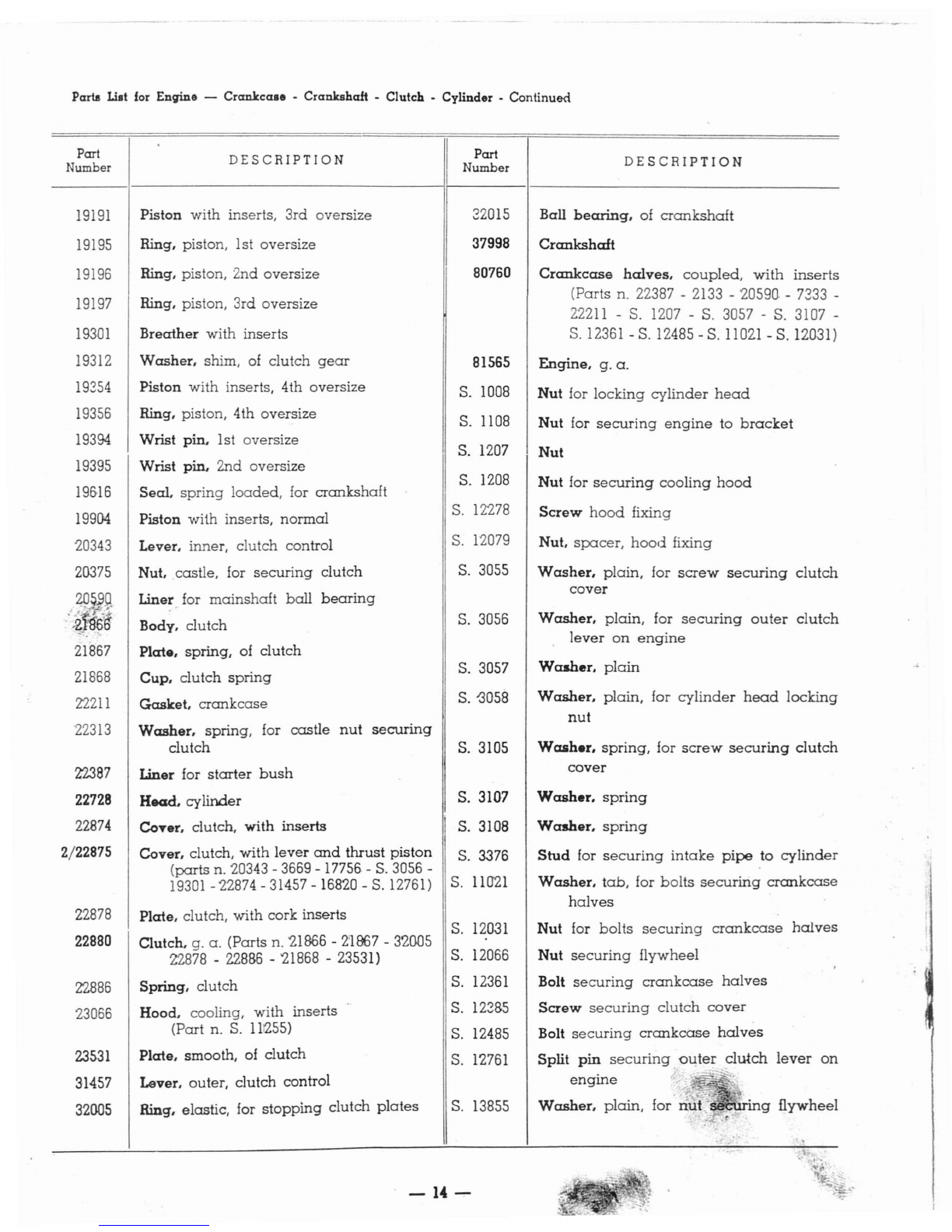
Pam
List
for
Engine -
Crankcase
-Crankshaft -Clutch •Cylinder -Continued
gflywheel
Part
Number
19191
19195
19196
19197
19301
19312
19354
19356
19394
19395
19&16
19904
20343
20375
49
Jlg
'iW9~
21867
21868
22211
'22313
22387
22728
22874
2/22875
22878
22880
22886
23066
23531
31457
32005
DESCRIPTION
Piston
with
inserts, 3rd oversize
Ring, piston, 1st oversize
Ring, piston, 2nd oversize
Ring, piston, 3rd oversize
Breather
with inserts
Washer.
shim,
of
clutch
gear
Piston with inserts, 4th oversize
Ring, piston, 4th oversize
Wrist pin, 1st oversize
Wrist pin, 2nd oversize
Seal.
spring
loaded,
for
crankshaft
Piston with inserts,
normal
Lever, inner, clutch control
Nut
•.
castle, for
securing
clutch
Liner for
mainshaft
ball
bearing
Body. clutch
Plate,
spring, of
clutch
Cup,
clutch
spring
Gasket,
crankcase
Washer,
spring, for
castle
nut
securing
clutch
Liner for
starter
bush
H.ad,
cylinder
CoTer, clutch,
with
inserts
Cover, clutch,
with
lever
and
thrust
piston
(parts
n. 20343 -3669 -17756 -
S.
3056 -
19301
-22874 -31457 -16820 -S. 12761)
Plate, clutch,
with
cork inserts
Clutch. g.
a.
(Parts n.
'21866
-
2'1967
-32005
22878 -
228B6
-'21868 -23531)
Spring, clutch
Hood. cooling, with inserts
(Part n.
S.
111255)
Plate,
smooth, of clutch
Lever. outer, clutch control
Ring, elastic, for
stopping
clutch
plates
Part
Number
32015
37998
80760
81565
S.
1008
S. 1108
S.
1207
S. 1208
S.
12278
S.
12079
S.
3055
S. 3056
S. 3057
S.
<3058
S. 3105
S. 3107
S. 3108
S. 3376
S.
110'21
S.
12031
S. 12066
S.
12361
S.
123B5
S. 12485
S.
12761
S.
13855
DESCRIPTION
Ball
bearing,
of
crankshaft
Crankshaft
Crankcase
halves,
coupled,
with
inserts
(Parts n. 22387 -2133 -20590. -7333 -
22211
-S. 1207 -S. 3057 -S. 3107 -
S.
12361
-S. 12485 -S.
11021
-S. 12D3l)
Engine.
g.
a.
Nut
for
locking
cylinder
head
Nut
for
securing
engine
to
bracket
Nut
Nut
for
securing
cooling
hood
Screw
hood
fixing
Nut.
spacer,
hood
fixing
Washer,
plain,
for
screw
securing
clutch
cover
Washer,
plain.
for
securing
outer
clutch
lever
on
engine
Washer.
plain
Washer,
plain,
for
cylinder
head
locking
nut
Wcuher,
spring,
for
screw
securing
clutch
cover
Washer.
spring
Washer,
spring
Stud
for
securing
intake
pipe
to
cylinder
Washer,
tab,
for
bolts
securing
crankcase
halves
Nut for
bolts
securing
crankcase
halves
Nut
securing
flywheel
Bolt
securing
crankcase
halves
Screw
securing
clutch
cover
Bolt
securing
crankcase
halves
Split
pin
securing
ou,ter
~utch
lever
on
engine
;
i' ,-"
Washer,
plain,
for
nu(
-14-

PARTS
UST
FOR
ENGINE
Gear
Box -
Brake
-Kiclaltarter -
Ventilator
-
flywheel
Magneto
TABLE
n.
39486
TABLE
IL
-;:
.
Part
DESCRIPTION
Pcut
DESCRIPTION
Number
Number
603
Screw
for
securing
coils
2210
Spring
for
starter
bush
619
Washer,
plain,
for
screw
securing
coil
2442
Nut for
securing
wheel
622
Washer,
shim,
of
breaker
2852
Screw,
long,
for
securing
fan
casing
624
Nut
2856
Screw,
short,
for
securing
fan
casing
625
Fork.
spring
2946
Screw
for
securing
fan
casing
cover
662
Terminal
3213
Screw
securing
condenser
and
felt
blade
674
Circlip for flywheel
extraction
7153
Seal,
rubber,
for
starter
bush
2021
Screw
for
joining
brake
drum
to
flange
7562
Ball
bearing,
inner,
of
mainshaft
2098
Split
pin
°for
locking
castle
nut
2148
Ring,
threaded,
for locking
mainshaft
ball
10260
Seal,
felt, of
starter
assembly
bearing
10788
Cable,
earth,
with
terminal
2195
Washer,
seal
locking I
11451
Spring,
return,
of
kickstarter
-
15-

PARTS
UST
•
Continued
ENGINE
Gear
Box
•Brake •Kickstarter -Ventilator -Flywheel
Magneto
,
.'
Part
Number
12501
14501
14651
15907
16351
16416
16417
16418
16419
16420
16421
17821
17824
17800
17887
17888
18106
18206
18445
~
18446
18447
a)
18558
18619
18620
18941
a)
19611
a)
20-321
a)
20322
a)
20323
a)
20324
20841
21148
a)
21898
21900
21931
22538
22539
22792
23g'22
DESCRIPTION
Ball
bearing,
outer,
of
mainshaft
Terminal
Stem,
selector
Flange,
female spline, with inserts
Drum,
rear
brake
Breaker
with
platinum
point
Axle,
breaker
Gusset,
contact
Ring,
insulating
Cam
Blade, felt, with
inserts
Selector,
gear
Gear,
2nd
speed
Layshaft
Spring
of
cush
drive
Gear,
outer
of
cush
drive
Seal,
spring-loaded,
of
mainshaft
Bush, slotted,
with
bronz~
liner
Gear,
low
speed
Ratchet,
starter
Circlip
retaining
shoulder
washer
Washer,
shoulder, normal,
of
gear
pinions
Drive, cushion, g.
a.
(parts
n. 17887 -17888
-
186'20
-
S.
10776 -31157)
Gear,
multiple
Condenser
Gear,
high spet::a
Washer,
shoulder, 1st oversize (.088")
Washer,
shoulder,
2nd
oversize (.096")
Washer,
shoulder,
3rd
oversize
(.104")
Washer,
shoulder, 4th oversize (.112")
Coil, ignition
Circlip
Mainshaft
Mainshaft, g.
a.
(parts
n.
S.
13768 -
21931
-
18447
-
1&558
-
17821
-21898 -16451)
Bush,
guide,
of
selector
stem
Fan
Casing
fan
Bush.
starter
Stator
with
inserts
(part
n. 16417)
Part
Number
25707
25710
25711
25741
25755
30412
31157
32494
39486
80019
80429
81568
S. 1209
S. 2314
S. 3055
S.
3103
S.
3105
S.
3105
S. 3109
S. 3110
bis
S. 6037
S.
1~7'
S. 10776
S. 11004
S.
11010
S.
12263
S.
12331
S."
12322
S. 12488
S.
13768
S.
13800
S.
13801
S. 13815
S. 13824
DESCRIPTION
Stator.
g.
a.
(parts
n. 603 -619 -622 -
&24
-625 -2213 -16416 -
1&418
-16419
-16420 -
1&4'21
-S. 3103 -S. 3105 -
-
S.
12.331
-
S.
12332 -
S.
13800 -
S.
1380-1
-
18941
-
20841
-10788 -23921 -
2.3922
-25710 -25711)
Coil,
low
tension,.
No.1
Coil,
low
tension,
No.2
Flywheel
with
inserts
Kickstarter
Roller for
multiple
gear
Washer.
plate,
of
cush
drive
springs
Ball
bearing
of
multiple
gear
Cover,
fan
casi!lg
Coil,
low
tension
No. 3
Spacer
between
mainshaft
bail
bearings
Flywheel
magneto,
q.
a.
(parts
·n.
25741 -
27856)
Nut
for
securing
layshaft
Nut,
castle,
for
securing
wheel
flange
W<:rsher.
plain,
for
screw
securing
stator
Washer,
sPr:ing, for felt
blade
Washer,
spring,
for
screw
securing
stator
Washer,
spring,
for
screw
securing
coils
Washer,
spring,
for
nut
securing
layshaft
Washer,
spring,
for
nut
securing
wheel
Circlip for
locking
multiple
gear
ball
bearing
Screw
for
securing
statOl
Rivet for
securing
plate
washers
Washer,
tab,
for
screw
securing
fan
Plate.
tab,
for kicks
tarter
bolts
Screw
securing
fan
Screw
retaining
cables
Screw
securing
blade
with
cam
greasing
felt
Bolt for
securing
kickstarter
Washer.
tab,
on
selector
stem
Washer
for
screw
retaining
cables
Washer.
insulating,
for
screw
retaining
cables
Washer,
plain,
for
nut
securing
wheel
flange
Washer,
plain,
for
nut
securing
layshaft
..
.
bl
of
t~
3
gear
pinions
In
respect
to
their
seat
must
be
contmned
between
.OOS"
and
.016".
(a) The
total.axlal
play
of
the
~dsseml
Y
th
normal
shoulder
washer
must
be
rep1a.
ced
by
another
with
proper
oversize.
Should
this
play
exceed
SOl
to
erances,
e
-16-

PARTS UST FOR ENGINE
Carburettor .Air
Cle<Dler
.Gear Shifter
TABLE
m.
Part I
DESCRIPTION
Part
DESCRIPTION
Number
Number
397
Packing, oil filling
and
draining
holes
2606
Spring of
throttle
slide
2121
Screw for
securing
gear
shifter
to
crank-
2610
Jet,
maximum
case
2611
Screw,
guide,
for
throttle
slide
2489
Pivot of
roller
carrying
stirrup
2612
Screw,
cable
stretcher
2508
Cap,
rubber,
for
low
tension
socket
2613
Nut,
jam,
of
cable
stretcher
screw
2600
Cap,
fastening,
of fuel
inlet
pipe
2615
Tickler
2601
Packing
of
inlet
pipe
2616
Clip,
tickler
2602
Pipe, fuel
inlet
Spring,
tickler
2603
Filter, fuel,
with
inserts
2617
2604
Screw for
securing
float.
chamber
cover
2618
Cover,
float
chamber
fo
-
17-
J
.,

PAllTS
US!
-
Continued
ENGINE
Carburettor
-Air
Cleaner
-
Gear
Shifter
Part
Number
2619
2620
2621
2622
2623
2748
2990
2990
4475
12080
12358
13&30
13883
13885
13990
13991
14142
14231
14233
14236
14427
14577
15496
HESS
18161
18166
18170
18411
19489
19492
19495
19630
19975
21089
21438
*
22258
DESCRIPTION
Packing
of float
chamber
cover
Float
Valve,
needle,
of float
Screw,
clamp
Clamp
Pivot,
threaded,
for
rocker
Cap,
oil filling
Cap,
oil
draining
Skid,
gear
shifting
Screw,
locking,
for
slotted
bush
Packing
between
cylinder
and
intake
pipe
Nut,
wing,
for
securing
air
cleaner
Stirrup,
roller
carrying,
of
gear
shifter
Pin,
roller
carrying,
of
gear
shifter
Screw,
stop,
of
throttle
slide
Spring
for
stop
screw
of
throttle
slide
Packing
for
air
cleaner
Atomizer
with
idling
jet
Clip for
taper
needle
Plug,
slotted,
for
hook
rod
Terminal,
pick-up
Rocker,
throttle
cable
Shifter,
gear,
g.
a.
(Parts
n.
31517
-
S.
32D6
-
Z2258
-
S.
13010
-
31515
-
S.
3'204
-
-
14883
-
22262
-
'2489
-
13885
-
4475
-
13514)
Cover,
air
cleaner,
with
inserts
Packing
between
air
cleaner
case
and
throttle
cable
support
Stud
for
securing
air
cleaner
to
carburettor
Gauze
in
air
cleaner
Support,
throttle
cable
Support,
throttl~
cable,
with
lever
and
rocker
(parts
n.
13990
-
13991
-
2748
-
S.
3104
-
S.
12012
-
14577
-
18411
-
2613
-
2612)
Slide,
throttle
Cup
for
spring
of
throttle
slide
Rod,
hook,
of
throttle
slide
Deflector,
mud
Needle,
taper
Socket,
low
tension,
for
earth
and
lighting
cables
Quadrant,
ratchet,
of
gear
shifter
Part
Number
22262
22733
24647
24930
2'4931
25897
25898
25900
25901
266&4
266B7
27991
*31514
31515
31517
S.
11-07
S.
3104
S.
3107
S.
3204
S.
3206
S.
12006
S.
12012
S.
12768
S.
12774
*S.13010
S.
13842
S.
13860
S.
14011
S.
14402
DESCRIPTION
Flange,
gear
shift
Pipe,
intake,
with
inserts
Circlip
retaining
float
needle
valve
Cover,
mixing
chamber
Packing
for
hook
:rod
Air
cleaner,
g.
a.
(Parts
n.
18170
-
S.
12'771i
-
18155
-
S.
13860
-
25898
-14N2)
Air
cleaner
with
inserts
Carburettor
with
throttle
cable
support,
rocker
and
studs
(Parts
n.
'25901
-
19489
-18166)
Carburettor,
Dell'Orto
TA
18E
Type
(with-
out
throttle
cable
support,
rocker
and
studs),
g.
a.
(Parts
n.
'2600
-
'2601
-
2602
-
2603
-
2615
-
2616
-2617 -
2604
-
2618
-
2619
-
2620
-
26'21
-
2606
-2623 -
2610
-
2611
-
'26667
-
'24647
-
14231
.
26'22
-
19495
-
2'4931
-24930 -
'26664)
Slide,
throttle,
.g.
a.
(Parts
n.
19492 -21089
-
14233
-
19630
-
14'236)
Body,
carburettor
Plug
on
air
cleaner
Lever,
gear
shifting
Roller,
control,
gear
shift
Spring
of
roller
carrying
stirrup
Nut
securing
intake
pipe
and
mud
deflector
Washer,
spring,
for
rocker
pivot
Washer,
spring,
for
intake
pipe
attachment
Split
pin
on
roller
pin
Split
pin
for
gear
shifting
skid
and
stirrup
pivot
Nut.
jam,
for
screw
locking
slotted
bush
Nut
for
rocker
pivot
Slipt
pin
Split
pin
PilL
taper,
iar
joining
quadrant
to
lever
Washer,
plain,
under
nut
securing
intake
pipe
and
mud
deflector
Washer,
plain
Packing
between
pick-up
terminal
and
crankcase
Screw
on
low
tension
socket
fbd d th th I
ver
31514
and
taper
pin
S. 13010.
C*)
Warning:
The
ratchet
quadrant
22258 of
gear
shl
ter
15
to e
or
ere
toge
er
WI
e
-
18-

--------------------------------
__
TABLE
IV.
81576
SJ20a......
s.Jloe
~
~
~\
.'"
2t~
l3081
....
PARTS
UST
FOR
CHASSIS
Fuel
Tank
-
Saddle
-Tool Box -
Bonnet
TABLE IV
Part
Number
2159
a)
2174
2319
2383
2809
2917
2939
2940
2941
2944
3221
4433
4435
5082
DESCRIPTION
BuHer
Ferrule
Packing
of filler
cap
Washer,
plain,
for
rear
attachment
of
saddle
Spring
for
bonnet
lock
Pivot,
hinge,
of
carburettor
side
shutter
Lever, lock, of tool
box
shutter
Spring
of tool
box
shutter
Pin
for lock
lever
Split
pin,
hinge,
of tool
box
shutter
Strap,
pipe
fastening
Pivot
Screw,
tie, of filler
cap
Rivet for
securing
hinge
of
engine
bonnet
Part
Number
10055
11032
11128
11177
11242
11653
11751
11760
12218
13481
1361-8
128'21
15123
DESCRIPTION
Nut.
wing,
for filler
cap
Rivet for
joining
support
plates
of
saddle
Spring,
return,
of
carburettor
side
shutter
Spring,
wire,
for
bonnet
frame
Plate,
connection
Hook.
purse
.hanging
Beading,
rubber,
for
engine
bonnet
BuHer,
stop,
of
carburettor
side
shutter
Spring
for
supporting
canvas
roll
Hinge
for
engine
bonnet
Pivot
fop
joining
connection
plate
to
saddle
frame
BuHer,
rubber,
for
spring
gusset
Pipe,
rubber,
from fuel
tap
to
carburettor
-19-
Table of contents
Other Allstate Scooter manuals


