Allstate 788.94493 User manual
OPERATING
INSTRUCTIONS
AND
PARTS
LIST
FOR
MOTOR SCOOTER
,..-----
MODEL NUMBER 788.94493
This is
the
Model
Number
of
your
Allstate
Motor
Scooter.
It will
be
found
on
a
plate
fastened
on
the
outside
of
the
hinged
door
under
the
seat. Always
mention
this
number
when
communicating
with
us regarding
the
Scooter,
or
when
ordering
repair
parts.
,..----
HOW
TO
ORDER REPAIR PARTS
All
parts
listed
herein
may
be
ordered
through
any
Sears
retail
or
mail
order
store. In
ordering
parts
by
mail
from
the
mail
order
store
which
serves
the
territory
in
which
you
live, Selling Prices
will
be
furnished
on
request
or
parts
will
be
shipped
at
prevailing prices
and
you will
be
billed accordingly.
WHEN
ORDERING REPAIR PARTS, ALWAYS GIVE THE
FOLLOWING INFORMATION:
1.
The
Part
Number
in
this List.
2.
The
Part
Name
in this List.
3.
The
Model
Number
of
the
item.
This list is valuable. It will
assure
your
being
able
to
obtain
proper
parts
service
at
all times.
We
suggest
you
keep
it
with
other
valuable
papers.
SEARS, ROEBUCK
AND
CO.
Scooterworks USA Inc.
5709
N.
Ravenswood
Chicago,
IL
60660
ph: 773.271.4242
fx:
773.271.5012


fii.
I - AllSTATE: •
Cruiaaire.
Motor
Scooter
Location
0/.
aerial
Number
Location
0/'
engine
Number
WARNING
In
order
to
keep
your
ALLSTATE
Scooter
In
perlect
runnmg
condillon
and
not to void
the
guarantee.
always
have
your
machme
repaired
at
a
Sers.
Roebuck
and
Co. Store.
Special
care
should
be
taken
in
regard
to
the
fuel
mixture which
should
be
regular
gasoline
and
.)Ij
of
the
make.
grade
and
1''1
the
amount
prescnbec
in this
booklet.
Ethyl
gasoline
ahould
never
be
used.
Do
not
use
Allatate
compounded
motor
oil
or
other
Premium
::
~
-'-.
Duty
Motor
Oil
with
detergents.
The
inexpenenced
operator
should
exercise
co
lIar.
m
applymg
front
wneel
brake.
to aVOid locklni;;
Fii.
2 .
Controla
0/
AUatate
Scooter
1.
Gear
change
tWlslgnp
with
c!u::n
control
lever·
2.
front
brake
lever·
3
Throllie
control
gnp.
(.
Light
and
dim.
mer
switch
-
5.
front
b-ake
,awl'
- 6
Rear
brw
pedal
-
7.
KJc:ltstarter • 8
Gem
.hilter
-
9.
Rear
brake
Jaws
-
10.
Clutch
•
11.
Carburellor.
au
cleaner
.
12.
Choke
control
lever
-
13.
fuel
cock
-3-
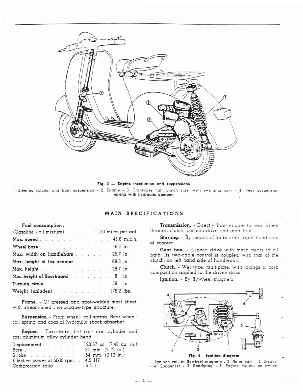
Fiq.
3 -
EDqine
inalallation
aDd
auapenaiona.
I
Sl~~rtng
column
and
front
!u!p~n!ion
•
2.
Engin~
•
3.
Crankca!~
hall.
clutch
sld~.
wIth
sWinging
arm
-
4.
R~ar
susp~nslon
apring
with
hydraulic
damp~r.
MAIN
SPECIFICATIONS
Fram
•.•
Of
pressed
and
spot.welded
steel
sheet.
with
stream-lined
monocoque-type
structure.
Suapenaion. •Front
wheel:
coil
spring.
Rear
wheel:
coil
spring
and
coaxial
hydraulic
shock
absorber.
Engin
•.•
Two-stroke. flat co:;t iron
cylinder
and
cast
aluminum
alloy
cylinder
head.
Displacement.
123.57 cc. (7.48 cu. in.)
Bore.
54
mm. (2.12 in.)
Stroke
54
mm. (2.12 in.)
Effective
power
at
5000 rpm 4.5
HP.
Compression ratio .6.5: I
Fuel
conaumption.
(Gasoline·
oil mixture)
Max.
speed.
Wheel
ba
...
Max.
width
on
handleban
Max.
lenght
of
the
scooter
Max.
height
Min.
height
of
floorboard.
Turning circl
•.
W.ight
(unladen)
130
miles
per
gal.
46.6 m.p.h.
40.4
in.
25.7 in.
68.3 in.
28.7 in.
8in.
59
in.
178.2 lbs.
Transmission.
-Directly [rom
enarne
to
rear
wheel
through
clutch.
cushion
drive
and
ge'ar
box
Starting.
-
By
means
of kickstarter.
nght
hand
Side
of
scooter.
Gear
box.
-
3-speed
drive
with
mesh
gears
in od
bath.
Its two-c::Ible control
IS
coupled
with
that
of the
clutch.
on
left
hand
side
of
handl~bars.
Clutch. -
Wet
type;
multiplate.
with
facrngs of corle
composition
applied
to
the
dnven
dISCS
Iqnition. -
By
fl'lwheel
magneto
...------------erJ~
/~
6
Fiq.
4 -
(qnilion
diaqram
I.
Ignition
coil
in
f1ywh~~1
magn~lo
_
2.
Rolor
cam
.
3.
Br~akcr
4.
Cond~n!~r
-
5.
Sporkplug
-
6.
Engin~
CUI-OU!
on
!wl!ch
-·4-
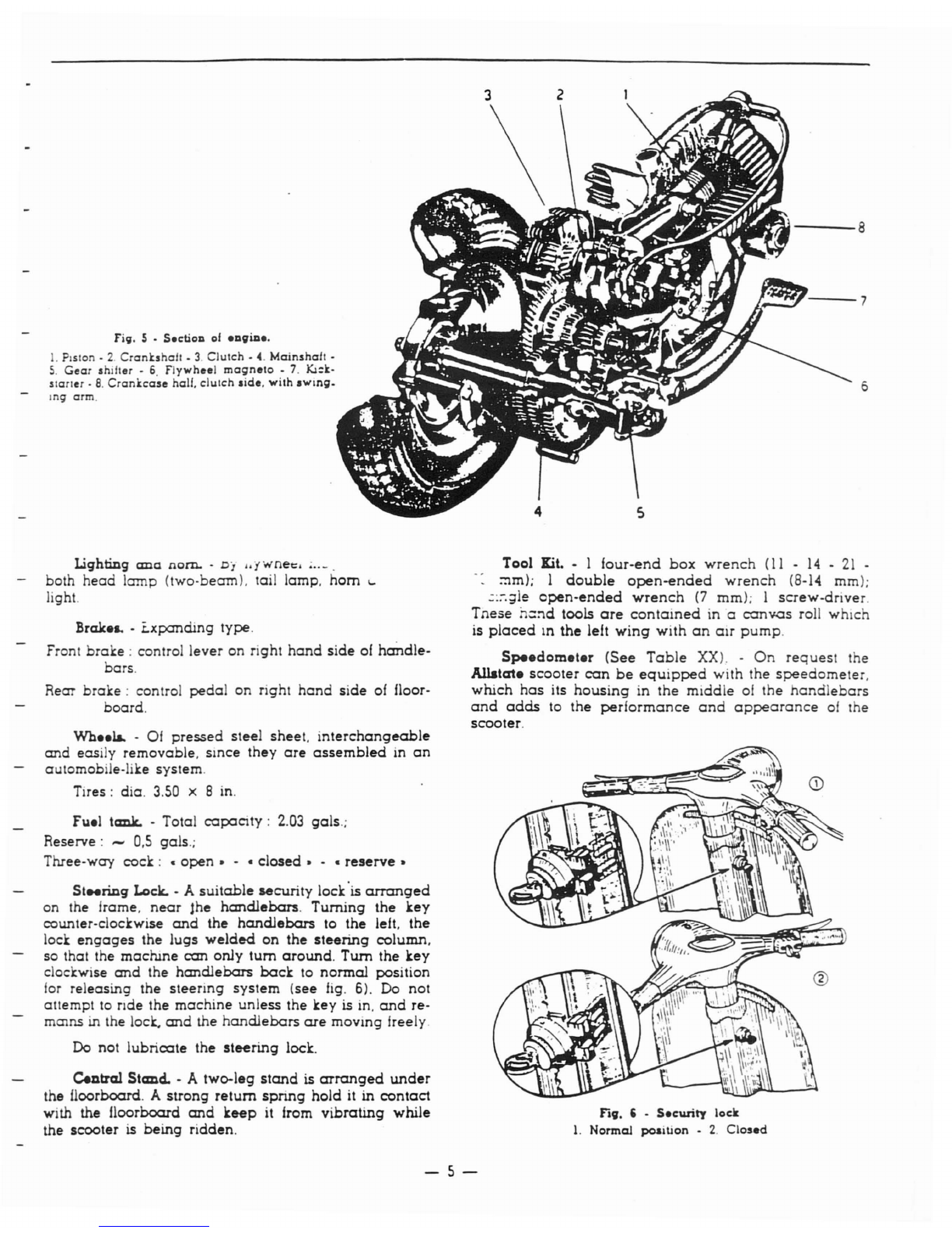
Fi9. 5 • S.c:tiOD
01
.DgiD
••
.
PIston·
2.
Cranbhafl
•
3.
Clutch
-
4.
Mainshafl
•
5.
Gear
shifter·
6.
Flywheel
magneto.
7.
Kl:k-
starter·
8.
Crankcase
hall.
clutch
aide.
with
aWing.
Ing
arm.
Lighting
ana
nom.
-
0]
••
fwnet.
;
..
_.
both
head
lamp
(two-beam). tail lamp.
hom
'-
light.
Brake&.
-Lxpanding type.
Front
brake:
control lever on right
hand
side
of
handle-
bars.
Rear
brake:
control
pedal
on right
hand
side
of floor·
board.
Wh
••
1&.
•01
pressed
steel sheet.
interchangeable
and
easily removable. since they
are
assembled
in
an
automobile-like system.
Tires: dia.
3.50
x 8 in.
Fuel tank. -Total
copacity:
2.03
gals.;
Reserve: -
0,5
gals.;
Three-way
cock:
copen.
- c closed
•.
c
reserve.
St
..
ring
Lock. -A
suitable
security
lock'is
arranged
on the lrame.
near
Jhe
handlebars.
Turning
the
key
counter-clockwise
and
the
handlebars
to the left. the
lock
engages
the
lugs
welded
on
the
steering
column.
so that the
madune
can
only
tum
around.
Tum
the
key
clod:wise
and
the
handlebars
beck
to
normal
position
lor releasing the
steering
system
(see
fig.
6). Do not
attempt to
TIde
the
machine
unless the key is in.
and
re-
mams
in the lock.
and
the
handlebars
ere
moving Ireely.
Do
not
lubricate
the
steering
lock.
Central
Stand.
- A two-leg
stand
is
arranged
under
the floorboard. A
strong
return
spring
hold
it
in
contact
with the floorboard
and
keep
it
from
vibrating
while
the scooter is
being
ridden.
---8
·r.r..~---7
6
Tool Kit. • 1
lour-end
box
wrench
(11
-
14
•
21
.
~m);
1
double
open-ended
wrench
(8-14 mm);
.:::-.;lle
open-ended
wrench
(7
mm); I
screw-driver.
Tnese
n::'ld
tools
are
contained
in a
canvas
roll
which
is
placed
In
the
left
wing
with
on
air
pump.
Speedometer
(See
Table
XX). -
On
request
the
Allatate
scooter
con
be
equipped
with the
speedometer.
which
has
its
housing
in
the
middle
of
the
handlebars
and
odds
to the
performance
and
appearance
01
the
scooter.
Fig. , -
Security
lock
1.
Normal
position
-
2.
Closed
-5-
r
2
~
-rr
~
I)
~
-.tt
-.rT
ftUJIIII -
l1li
~
i
tB
y•
~"
: 3
I
\
L-.T1Ul[
•
",
;
15--r.-+
;-7
'--
.:.'-.",J
'
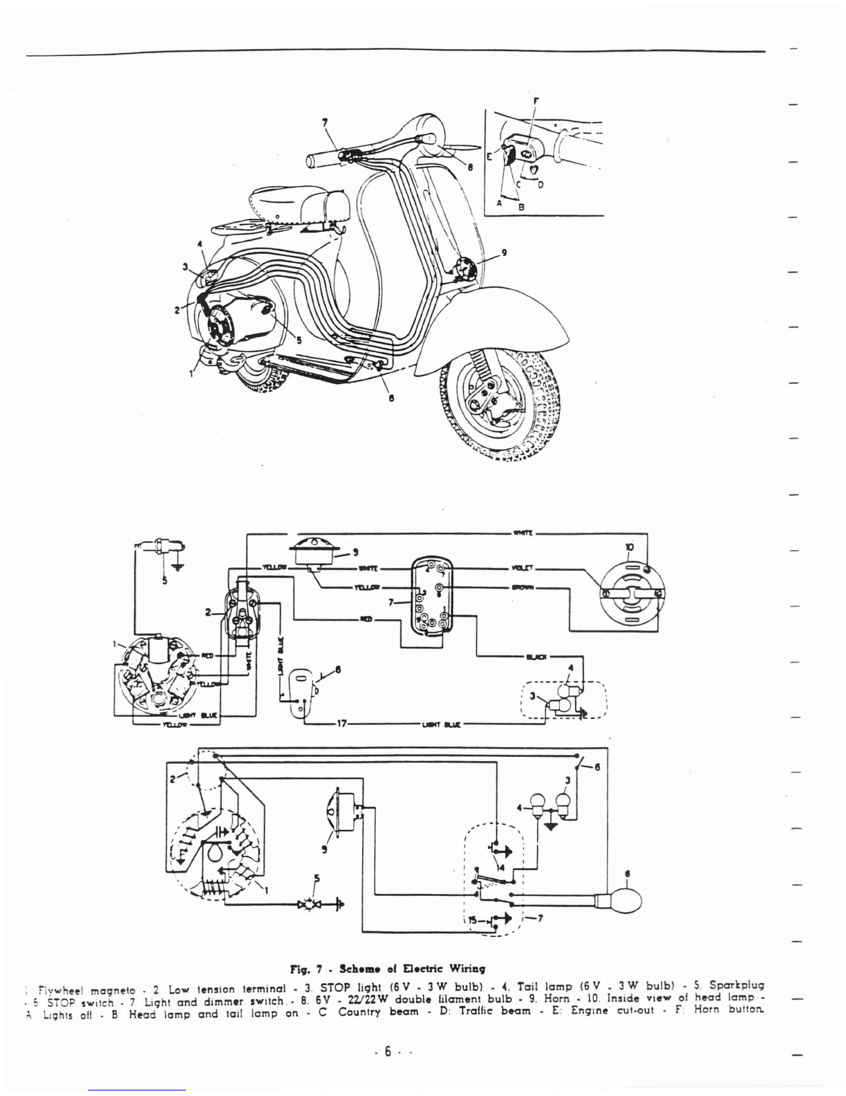
Fiq. 7 • Scheme
01
Eleetric
Wirillq
:
fiywh~~1
magn~lo
. 2 Low tltnsion
lltrminal
•
3.
STOP
light
(6
V • 3 W
bulb)
•
4.
Tail
lamp
(6
V • 3 W
bulb)
•
5.
Sparkplug
. 5 STOP
switch.
7Light
and
dimmer
SWitch
.•
8.
6V
.
W22W
double
filament
bulb·
9.
Hom·
10.
Inside
view
of
hltad
lamp
•
.
~
LIghts
011
•BHltad
lamp
and
tail
lamp
on
. C
Country
bttam
•
D:
Traffic
bttam
•
E:
Englnlt
cut-out
.
f.
Horn
bullon.
. 6
..
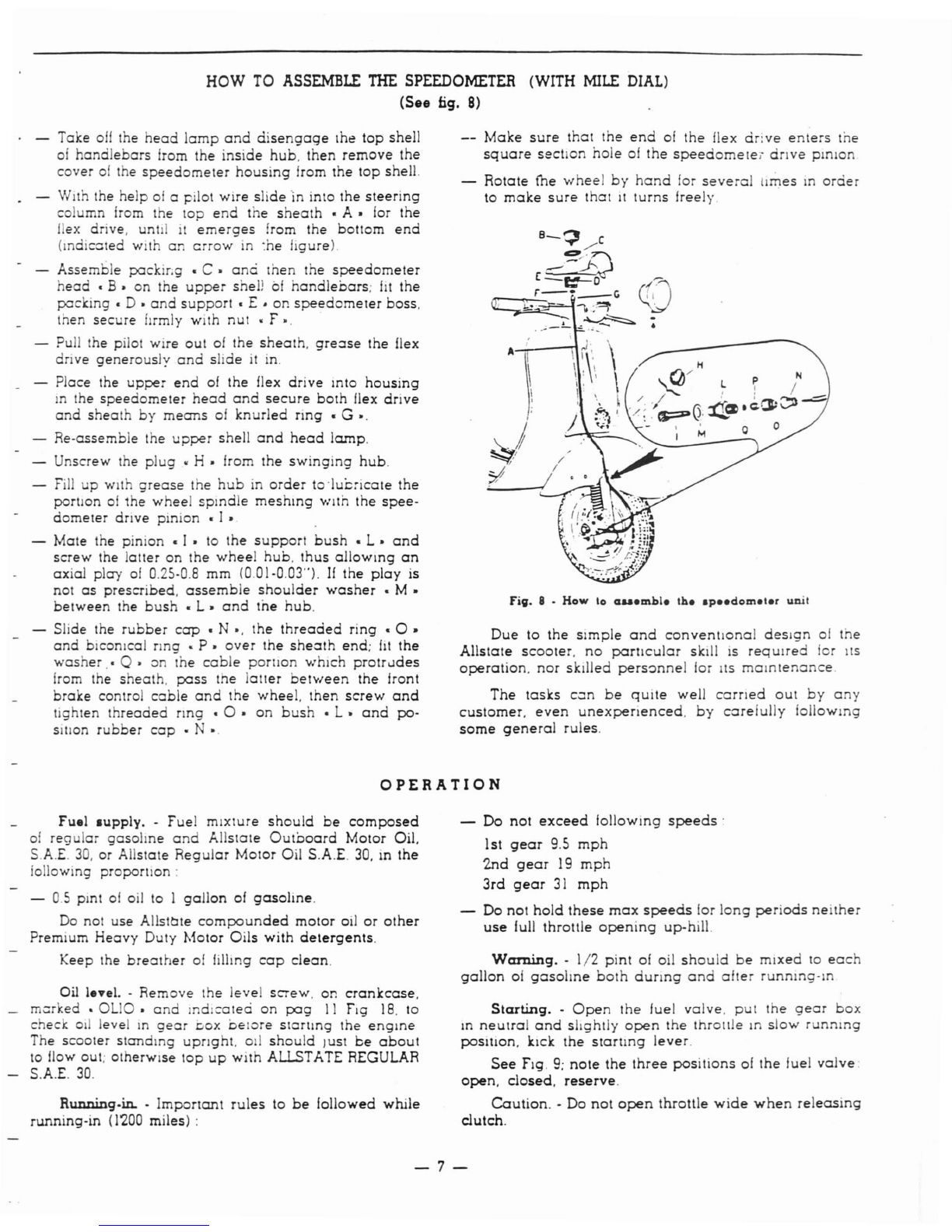
HOW
TO
ASSEMBLE
THE
SPEEDOMETER
(WITH
MILE
DIAL)
(See fig.
8)
Take
011
the
head
lamp
and
disengage
Ihe
top
shell
of
handlebars
from the
inside
hub,
then
remove
the
cover
of
the
speedomeler
housing
from
the
top
shell.
-WIth the
help
of
apilot
wire
slide
'in
into the
steering
co umn from the
100
end
the
sheath
•
A.
for
the
fex drive. unt
it
'emerges
from the bottom
end
(mdic:Jled with
an
crrow
in
:he
figure).
Assemble packir;g •
C.
ana
Ihen the
speedometer
head.
B.
on
the
upper
sheD
of
handlebars;
fIt
the
packing.
D •
and
support.
E •
on
speedometer
boss,
then
secure
fJrmly with
nut
• F •.
Pull the pilot wire
out
of
the
sheath,
greose
the flex
drive
generously
and
slide
it
in.
-Place the
upper
end
of
the flex
drive
mto
housing
mthe
speedometer
head
and
secure
both
flex
drive
and
sheath
by
means
of
knurled
ring
• G
'.
Re-assemble the
upper
shell
and
head
lamp.
Unscrew the
plug
•H• from the
swinging
hub.
Fill
up
with
grease
the
hub
in
order
to'luc:lcate
the
portion
of
1he
wheel
spmdle
meshing
...
nth
the
spee-
dometer
drive pinion • I •
-Mate the pinion • I • to
the
support
bush
• L •
and
screw
the
latter
on
the
wheel
hub,
thus
allOWing
an
axial
play
of
0.25-0.8
mm
(0.01-0.03"). If the
play
is
not
as
prescribed.
assemble
shoulder
washer
• M •
between
the
bush
•
L.
and
toe
hub.
-Slide the
rubber
cap
• N
'.
the
threaded
ring
•0 •
and
biconlcal ring •
p.
over
the
sheoth
end;
fit
the
washer
.•
Q.
on the
cable
portIon
which
protrudes
from the
sheath,
pass
the
latter
between
the
front
brake
control
cable
and
the
wheel.
then
screw
and
tighten
threaded
nng
•
O.
on
bush
•
L.
and
po-
SItion
rubber
cap
• N
'.
Make
sure
that
the
end
of the flex
drive
enters
the
square
sect
on
hole
of
the
speedometei
dnve
pinion
Rotate
fne
wheel
by
hand
for
several
times
In
order
to
make
sure
that
It
turns
freely
Fig.
8 • How
'0
cu
...
mel.
lb.
ap
••
dom.'.r
unit
Due
to
the
Simple
and
conventional
deSign
of
the
Allstate
scooter,
no
particular
skill
IS
requITed for
ItS
operation,
nor
skilled
pers~nnel
lor
ItS
maintenance.
The
tash
con
be
quite
well
carned
out
by
any
customer.
even
unexpenenced.
by
core/ully
follOWing
some
general
rules.
OPERATION
Fuel
lupply.
-Fuel mIxture
should
be
composed
of
reg
lar
gasohne
and
Allstate
Outboard
Motor Oil.
S.A.E.
30.
or Allstate
Regular
Motor Oil S.A.E. 30. in
the
following
proportion:
-
0.5
pmt
of
oil to I
gallon
of
gasoline.
Do
not use AllsttIte
compounded
motor
oil
or
other
Premium
Heavy
Duty Motor
Oils
with
detergents.
Keep the
breather
of
filling
cap
clean.
Oil level. -Remove the level
screw,
on
crankcase,
mer
ked •
OLIO,
and
mdlcateci
on
pag
II Fig
18.
to
check
01
level
10
gear
DO>:
belore
slartlng
the
engine
The
scooter
standing
upnght.
011
should
Just
be
about
to flow out; otherWise
top
up
with
ALLSTATE REGULAR
S.A.E.
30.
Running.in. -
Important
rules
to
be
followed
while
running-in
(1'200
miles) :
-Do
not
exceed
follOWing
speeds'
1st
gear
9.5
mph
2nd
gear
19
mph
3rd
gear
31
mph
Do
not
hold
these
max
speeds
for
long
periods
neither
use
full throttle
opening
up-hill.
Warning.
-
1/2
pint
of oil
should
be
mixed
10
each
gallon
of
gasoline
both
dunng
and
after
running-In
Starting.
-
Open
the
fuel
valve,
put
the
gear
box
m
neulral
and
shghlly
open
the
throllJe
In
slow
running
poSItiOn, kick
the
slartlng
lever.
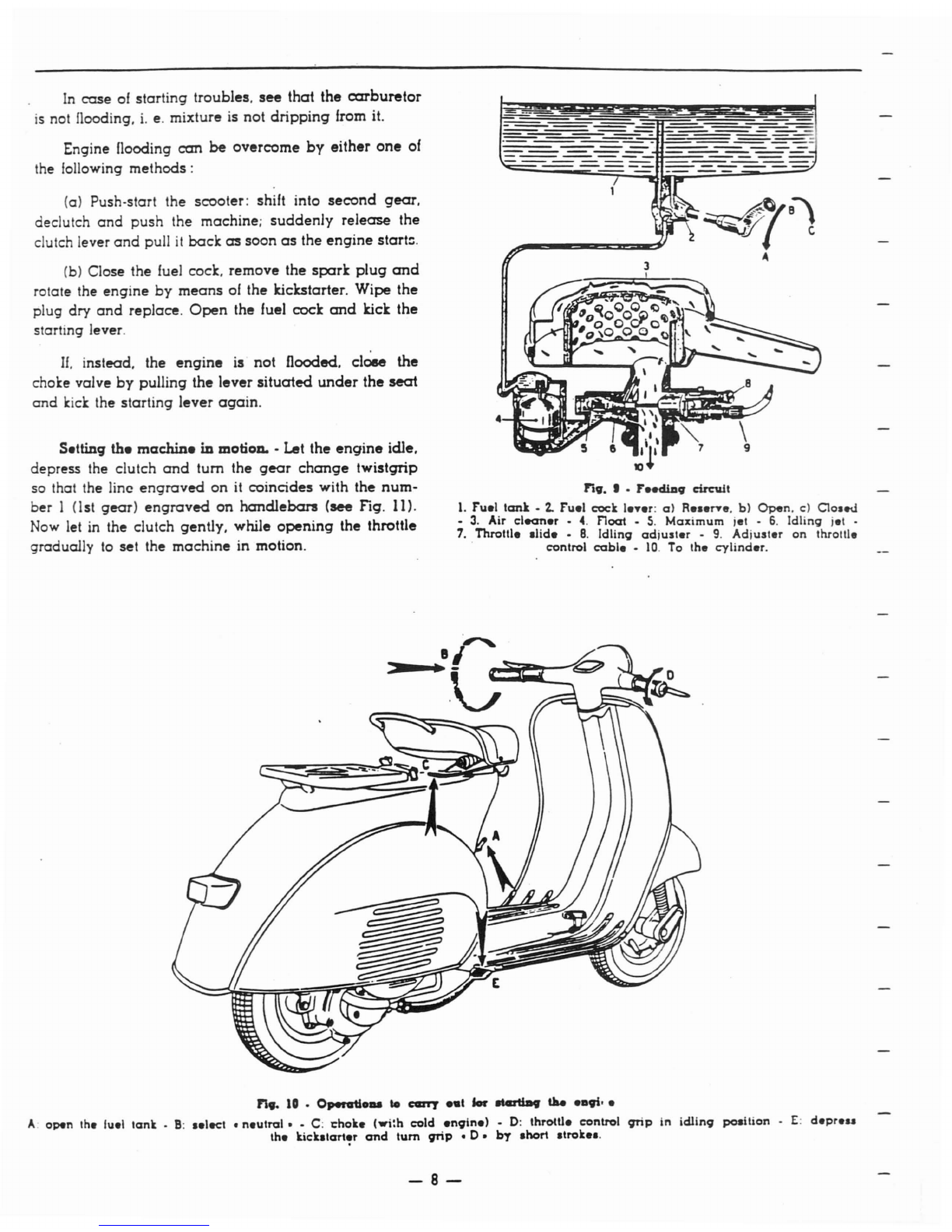
See
Fig.
9;
note
the
three
positions
of
the
fuel
valve.
open,
closed.
reserve.
Caution.
-Do
not
open
throttle
wide
when
releasing
clutch.
-7-
In
case
of
starting troubles,
see
that the
carburetor
is
not flooding, i. e. mixture is not
dripping
from it.
Engine flooding
can
be overcome
by
either
one
of
the following
methods:
(a) Push-start the scooter: shift into
second
gear,
declutch
and
push
the machine;
suddenly
release
the
clutch lever
and
pull
it
back
as
soon
as
the
engine
start::.
(b) Close the fuel cock, remove the
spark
plug
and
rotate the engine
by
means
01
the !tickstarter. Wipe the
plug dry
and
replace.
Open
the fuel cock
and
!tick the
starting lever.
If,
instead. the
engine
is not flooded. close the
choke valve
by
pulling the lever
situated
under
the
seat
and
kick
the starting lever
again.
Setting the
machin.
in
motioD. •Let the
engine
idle,
depress the clutch
and
tum
the
gear
change
twistgrip
so that the line
engraved
on
it
coincides with the
num-
ber 1(lst
gear)
engraved
on
handlebars
(see Fig. 11).
Now
let in the clutch gently, while
opening
the throttle
gradually
to
set the machine in motion.
~.~
~
J
"
•.
I .
FeediD.
c:ircW1
1.
Fuel
tank
•
2..
Fuel
coc:k le'l'er:
a)
ReserYe,
b)
Open,
c)
Closed
•
3.
Air
cleaner
-
4.
Float
-
5.
Maximum
iet -
6.
Idling
jet -
7.
Throttle
slide
•
8.
Idling
adjuster
-
9.
Adjuster
on
throttle
control
cable
-
10.
To
the
cylinder.
"
••
10
•
Openrtlo_
..
carr
..
I
lor
atcatmv
tIM ealli· e
A:
open
the luel
lank
_
B:
selecl
•
neutral
••
C:
choke
(wi:h
cold
enqine)
•
0:
throtUe
control
qrip
In ic:lllnq
position
-
E:
depre
..
the
kicltstart!r
and
tum
qrip
•
D.
bT
short
slrokes.
-8-

G.ar
change
••
Alter
reaching
the
required
speed
in
1st
gear, close quickly the throttle,
depress
the clutch
and
tum
the
gear
change
twistgrip
so
that
the
engraved
line is opposite
number
2(2nd
gear)
let in the clutch
and
open the throttle gradually.
Repeat this procedure lor
changing
into 3rd
gear.
(See Drive system on
fig.
11
l.
For changing down. close the throttle.
depress
the
clutch
and
tum
the
gear
change
twistgrip to the requi-
red position.
Fi9.
11
•Dri
..
IYllelll
I.
Gear
change
twillgrip
•
2..
Clutch
cantrol
lever
•
3.
Gear
change
conlrol
cablel
-
Gear
.hiller
•
5.
Selector
Ilem
-
6.
S.lector
•
7.
lit
gear
pinion.
8.
2nd
\lear
pinion
-
9.
3rd
\lear
pinion •
10.
Mainshall -
II.
Cuah
gear
•
12..
Clutch.
N.B.
-
POI
IlionI
1·2·3
of
the
gear
cban\le
twUl\lrip
correlpond
10
III.
2nd
and
3ro:!
\lear
relpeeuvely;
•
C.
indJcatel
the
neutral polilion.
When you reduce the
speed
of
your
machine.
chan-
ge
down with no delay.
Do
not
tum
the
gear
change
twistgrip while
the
en-
gine ia not running.
AI
.oon
as
gear
change
trouble.
ariMo
particularly
when
the control
become.
hard.
cuatome,..
should
haYe
their
machin..
adjusted
at
a
Sears
Roebuck
and
Co•
•tore.
Fig. 12 -DiamaDtliD, U.e troDI
wll
..
L
Tir
...
-The
wheels
are
interchangeable.
i.
e. they
can
be
assembled
either
in (ront
or
rear.
provided
oi
.
course
that
they
are
enflated
to
pressures
respecltvely
hereunder
prescribed.
When
aflat tire
is
to be
replaced.
unscrew
the
lour
nuts
which
secure
the
wheel
to its flange. pull
wheel
sideways
off
the
studs
(see
fig.
12),
repair
it
or
replace
with
spare
wheel.
To
remove
the
tube,
deflate
it
itrst.
then
separate
the
felloe from
the
ring
by
unscrewing
the
nuts
which
join
them
(see
fig.
l~).
Tire
pressure
should
be
18
psi
on
rear
wheel.
11
psi
on
front
wheel.
If
the
Allstate is
ordinarily
ridden
by
both
driver
and
passenger,
the
pressure
01
the
rcer
tire
should
be
28
psi.
StoppiDg
the
en~.
-
Push
the
cut-out
button
(see
fig.
7.
letter
"E
..
);
fuel
vapors
remain
in the
cylmder
in
this
way,
and
the
next
start
will be
much
easier.
-9-

Brake
adju.tment.
-Brakes
are
properly
adjusted
if:
-the wheel rotates freely
when
respective control
lever or
pedal
are
in resting position;
-the braking action startS
as
soon
as
respective
controls
are
operated.
These conditions
are
achieved
adjusting
the
cables
by
means
of
screws indicated with
an
arrow
in Fig.
14.
®
fill.
14
•Brake ad!llStIDe"
Adju.tment
of clutch controL -
Adjustment
of
clutch
controls is
achieved
operating
on.
adjusting
nut
(aJ.
screwed
to
the
engine
braket
(see Fig. 15).
by
means
of
open
end
wrench
82199 in the tool roll.
a
fiV.
15
•
Ad!uatmeat
of
dutch
coatrol
0)
A.djustlng
nul
-b)
Clutch
leyer.
engine
side
The
cable
is
to
be
tensioned
or
loosened.
as
the
case
may
be.
so
that
control lever.
on
handlebars.
makes
a
stroke
of 2mm.
(0.078")
before
lever
(b).
on
engine.
starts
moving.
Wrong
play
in the control
may
cause
the clutch
plates
burning
out
even
in
normal
riding
conditions.
MAINTENANCE
Slow
running
adjwatm.nL -
No
han'" tool is
required
for
this job; idling revs
can
be
raised
by
simply tighten.
ing the screw which
presses
on
carburetlor
cover
and
vice-versa.
Cleaning the
scoot.r.
-Brushing
kerosene
and
wiping dry with
dean
rags
is
advisable
for
outside
cleaning
of
engine.
All
painted
surfaces
should
be
washed
with
water.
rinsed
by
means
of
a
sponge
and
wiped
dry
with a
chamois.
Do
not use kerosene
on
such
surfaces.
since
it
damages
paint
and
turns
it
dull.
If
necessary.
blow
the
head
lamp
reflector clean
or
wipe
oil
dust
with a
very
soft feather.
Do
not
use
a
cloth
and
keep
your
fingers oil refiector
surface.
Befor
...
tting
the
mac:hiD.
in
motion.
(if
it
has
been
delivered
directly to the
customer
by
the
Factory)
check
oil level in
gear
box
by
unscrewing
from
the
cranckase
the
level
screw
marked
•
OUO.
(see
Fig.
181.
The
scooter
standing
upright. oil
should
just
be
about
to
now
out.
AJter
the
tint
600
mil...
-
Replace
oil in the
gear
box
by
the
procedure
as
explained
in the
lubrication
chart.
page
11.
The
crankcase
can
be
drained
through
the
hole
indicated
in
Fig.
18.
10
-
Eury
1.200
mil
••
:
(1)
-Remove the
air
cleaner
from the
carburettor
and
wash
it in a
30~.
gasoline-oil bath.
(2) -Check oil level in the
gear
box (see
above).
(3) •Clean the
sparkplug
electrodes with
very
fine
emery cloth or suitable files.
and
adjust
the
gap
to
.6
mm. (.023").
Inspect the insulation material
of
sparlcplug; re-
place the latter
if
the porcelain
is
cracked.
Whash
with
neat
gasoline.
Use the
sparkplug
type
AllSTATE
No.
A4
ISO.
Important:
using the
proper
type
of
sparkplug
will
eliminate
many
engine
troubles.
(4) •Clean the two lubricators
on
front wheel
hub
and
refill them
by
means
of
agr-ease gun.
NoB.
•
All
operatioDa indicated
hereunder
ahould
be
carried out
by
aSEARS atore.
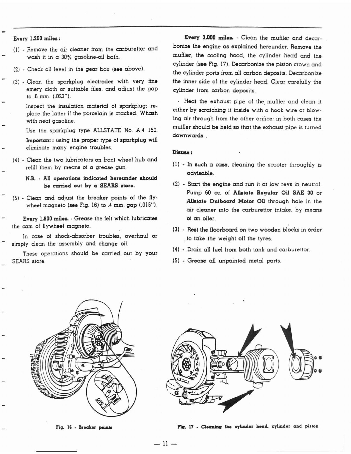
(5)
•
Clean
and
adjust
the
breaker
points
of
the fly-
wheel
magneto
(see Fig.
16)
to
.4
mm.
gap
(.015").
Eury
1.800
mil
...
-
Grease
the felt which
lubricates
the cam
of
Ilywheel magneto.
In
case
01
shoclc-absorber troubles,
overhaul
or
simply clean the
assembly
and
change
oil.
These operations
should
be
carried
out
by
your
'SEARS
store.
Fig.
15
•
Ir.aker
poiAta
Enry
3.000
milu.
-
Clean
the muffler
and
decar-
bonize the
engine
as
explained
hereunder.
Remove the
muffler. the cooling hood. the
cylinder
head
and
the
cylinder (see Fig.
17).
Decarbonize
the piston crown
and
the cylinder ports from
all
carbon
deposits.
Decarbonize
the inne:-
side
of
the
cylinder
head.
Clear
carefully the
cylinder from
carbon
deposits.
.
Heat
the
exhaust
pipe
of
the. muffler
and
clean
it
either
by
scratching
it
inside
with ahook wire
or
blow-
ing
air
through
from the
other
orifice; in
both
cases
the
muffler
should
be
held
so
that
the
exhaust
pipe
is
turned
downwards
..
Diauu
:
(l)
•
In
such
a
case,
cleanin9
the
scooter
throughly is
advisable.
(2) •
Start
the
engine
and
run
it
at
low
revs
in neutral.
Pump
60
ce.
of
Allatate
aegular
Oil SAl:
30
or
Allatate
Outboard
Motor Oil
through
hole in the
air
cleaner
into
the
carburettor
iniake.
by
meana
01
an
oiler.
(3)
•Rest the
floorboard
on
two
wooden
blocks in Order
.to
take
the
weight
off
the
tyres.
(4)
•Drain all fuel from
both
tanlc
and
carburettor.
(5)
•
Grease
all
unpainted
metal
parts.
Fig.
17
•
Q.-iDlJ
the
cyliDd.r
laeacL
cyliDd.r
cuad
pUlOD
-
11
-

LUBRICATION CHART FOR AIJ.STATE
PART
TO
BE
I
OPERATION
TI
ME
TYPE
OF
LUBRICANT
LUBRICATED I
Enqine
,Mix
qasoline
'With
the
followinq
amount
of
At
each
rdfillinq of
the
fuel
Allstate
Regular
SAE
30
or
lubricatinq
oil:·
tank
Allstate
Outboard
Motor Oil
i-
0.5
pint
of oil
to
I
qallon
of
qasoline.
Gear
Box
I
Warm
up
the
engine
and
drain
off
all
oil. After
the
first 600
miles
IPour
some
fresh oil in
and
run
the
engine
lor
a
lew
seconds.
Dram
again
and
refill
with
Allstate
Regular
SAE
30
ne";
oil.
Refill with
new
oil to oil levcl hole.
Every
1200
miles
front
wheel
hub
Lubricate
with
grease
gun.
Every
1200
mlles
Hiqh
Pressure
Chassis
Grease
Joints on
brake
I
Grease.
Every
1200
miles
Allstate
all
-
purpo.e
control.
I
Gear
Lubricator
SAE
140
Shock·absorber
Change
oil.
Only
when
the
shock-absorber
Allstate
Shock
is
out
of
order
Absorber
nuid
I.
Control
cables
C1l1OTl
and
lubricate.
Every
1800
mil.s
Allslate
all
-
purpose
Gear
Lubricator
SAE
140
fell
01
nywheel
Small
of
grtMIse
on
the
fel:!.
i
Every
11m
miles
Allstate
BtMJring
Grease
spot
I
cam
I
Ratchel
quadrant
Grease.
Every
1800
miles
Allstate
all
-
purpose
01
qear
.hiller
II
Gear
Lubricator
SAE
140
I
["&II(
U8IIUTtO
IU.S
Taft
IlGULU
SA(
JO
(lit
aLL)
Tift
OY!'IOA!!Q
Ml)!pI!
ill.
Fi,.
II
•Lulniccrtioll
acbellle
I. Filling
hole
-
2.
Draining
hole
-
12-
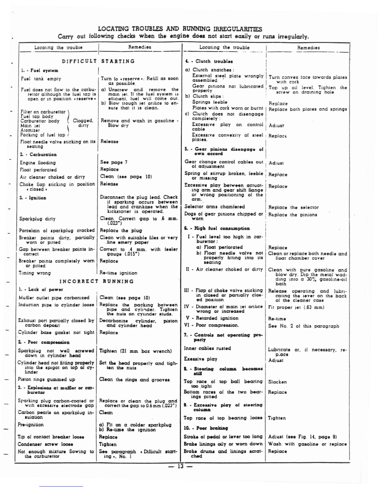
LOCATING TRO
UBLES
AND RUNNING IRREGUlARITIES
Carry out following checks
when
the
engine
do
••
not start easily or runa irregularly.
INCORRECT
BUNNING
DIF'FICULT
STARTING
R.-hm.
S..
No. 2of lhis
paragraph
AdilUt (a
..
Fig.
14.
page
9)
Wash
with
gaaolin.
or
r.plac.
R.plac.
Clean
with
pure
gasoline
and
blow
dry.
DIp
the
m.tal
wad-
ding
inlo
a30%
gasolln,-011
bath
R.l.as.
operating
and
lubn-
callnq
the
I.v.r
on
lhe
back
o(
the
c1.aner
eale
fit
proper
jet
<.63
mm)
Replac.
Clean
or
r.plae.
both
needle
and
floal
chamber
cov.r
I
I
:ar.
!
Lubricat.
or,
if
nec.asary,
re-
p:ac.
AdllUt
become.
I
col_
4.
•
Clutch
trouh!'
••
Locating
the
trou~_le'
__
'_I
Remedies
I
a)
Clutch
snatchel:
I
Ext.rnal
steel
plate
wrongly
I
Turn
convex
bee
towards
plates
assembled
. . IWilh
cork
Gear
pinions
not
lubrlcaled
j
Top
up
oil
level.
Tighten
the
properly
,
screw
on
draining
hole
bl
Clutch
llips:
Springs
leable
Rep~ace
Plates
with
cork
worn
or
burnt
Replace
both
plales
and
springs
c)
Clu:ch
does
not
disengage
compl.lely
:
ExceSlive
play
on
control
Adjust
cable
ExceSilve
conv.xity
of
Ileel
Replact.
plat.l.
tx.uiv.
play
50
•
High
ha.l
COIIaWDplioD
I •
Fu.l
l.v.l
too
high
in
bur.llor:
a)
noat
perlorated
b)
noat
n.edl.
valve
not
properly
hlling
into
ill
••
ating
II
•Air
cleaner
chok.d
or
dirty
S
••
GaClr
piDiolU
cli
••
1l9C19.
of
OWIl
a~~orci
Gear
cnange
conirol
cabl.1
out
Adiusl
01
ad,lUtm.nt
Spring
of .tilT\lp
broken,
le.bl.
Replace
or
miumg
Exc.ssive
play
belw
..
n
actuat-
Replace
ing
ann and
g.ar
ahift
llanoe
or
wrong
positioning
of
the
arm.
Sel.ctor
annl
chaml.red
Replace
'lhe
selector
Dog.
of
g.ar
pinionl
chipped
or
:
R~plac.
the
pinionl
worn
'
7
••
CoDuola
_t
opeJ'ClUD9
pro-
peri,
Inn.r
cabl..
rlUted
m •
nap
of
choke
valve
lticking
in
cloa.d
or
partially
c1e.-
ed
polltlOn
IV
-
Diam.t.r
of
main
j.l
orihce
wrong
or
increaaed
V •
R.tard.d
ignition
VI
•
Poor
compr.uion.
...
SteeriD9
atiJf
Top
rac.
of
top
ball
bearing
Slack.n
too
.tight
Bottom
rac..
of
the
two
~-
Replac.
ing.
pitted
1
Q.
•
p_
bralI:iD9
Stroke
of
~
or
l.ver
too
1000g
Brake
lininga
oily
or
wom
down
Brait.
cirwna and
lininga
aerat-
checl
I
..
Eac.ui..
play
of
....
riDg
collUDD
Top
rac.
01
top
bearing
loos.
Tighten
Remedies
R.-time
ignition
S
..
page
7
R.plac.
Clean
(s.e
page
10)
R.I.cae
R.I.a.e
Turn
(0
•
reserve
•.
Refill
as
soon
as
possible.
aJ
Unscr.w
and
remove
the
mam
,et.
II
Ihe
luel
system
i~
elhclent, tuel will
come
out.
b)
B10."
Irough
,et
orifice 10
en-
sure
that
it
IS
clean.
Remove
and
wash
in
gasoline
-
Blow
dry
Diaconn.ct
Ihe
plug
lead.
Check
if
sparking
oc:urs
b.tween
lead
and
erankcae
when
Ihe
kicutart.r
is
operat.d.
Clean.
Correct
gap
10
.6
mm.
(.023-)
Replace
th.
plug
Clean
with
.uitabl.
file.
or
v.ry
.tin
••
m.ry
paper
Correct
10
.4
mm.
with
I
••
l.r
gaug.
(.OlS-)
R.place
Tight.n
(21
mm
box
wr.nch)
Clean
the
ringa
and
groov
..
Set
the
bead
properly
and
tigh·
t.n
the
nUll
R.p1ace
or
c1.an
the
plug
and
corr.ct
th.
gap
to
0.6
mm <.023-)
Clean
0)
FIt
CD
a
cald.r
aparkplug
b)
Re·tim.
the
ignition
R.p1ac.
Tigbl.n
Ie
s..
paragrapb
•Dillieu1t
atart·
ing.,
No. I
Locallng the
trouble
1
••
F'lIel
.y.lem
fu.1
tank
empty
fuel
does
not now to Ihe
cClTbu-
rettor
all
hough
the
luella;)
is
open
or
In
position
•
r.serve
•
filler
on
carburetlor
(
fuel
tap
body
Carburettor
body
Clogg.d,
Main lei \
diTlY
Atomizer
Packing
of
fuel
tap
I
float
needle
valve
sticking
on
ill
seating
1.
•CMkllUCltiOIl
Engin.
llooding
float
perforated
Air
cleaner
chok.d
or
dirty
Choke !lap
Iticking
in
position
•
closed.
3.
•
lpi
tiOll
Sparkplug
dirly
Pore.lain
of
lparkplug
crack.d
Break.r
poi
nil
dirty,
partially
worn or
pitted
Gap
betw.en
break.r
poinl.
in·
correct
Br.ak.r
points
complet.ly
worn
or
pitl.d
Timing
wrong
1
.•
Lack
of
pow.r
I
Muli.r
outl.1
pipe
carbonized
I
C1.an
(I"
page
10)
Induction
pipe
10
cylind.r
loose
Replace
the
packJng
betw
••
n
Pipe
and
cyli"\d.r.
Tlghlen
lb.
null
on
CYllnd.r
Iluda.
Deearbonize
cylind.r,
pi.ton
and
cyllnd.r
head
R.plac.
Exhauat port
partially
closed
by
carbon
d.poait
Cylind.r
ba..
gcak.t
not
tight
Sr-arking
plug
carbon-eoat.d
or
wllh
'XC'Sll'r'
.leclrod.
gap
Carbon
peoria
on
.parkplug
in·
'1Ilation
Pre-ignition
Tip
01
~ntact
break.er
100M
Cond.naer
aer.w
100M
Nol
.nough
mixture
Dowing
the
earbur.lIor
1. •
P_r
~omJWeouiclia
Spark
plug
not
w.ll
aer.wed
down
in
cylind.r
beacI
Cylind.r
head
not
titting
properly
into th
••
pigot
on
tot>
01
cy.
lmd.r
Pi.ton
rings
gummed
up
3
.•
Exploaiou
ClI
.WIl.r
or
car·
bllT.llol
-
13-

-14-
-i
_________
p
ART
S
LIS
T _
TABLE
I
@
19~16
,26278
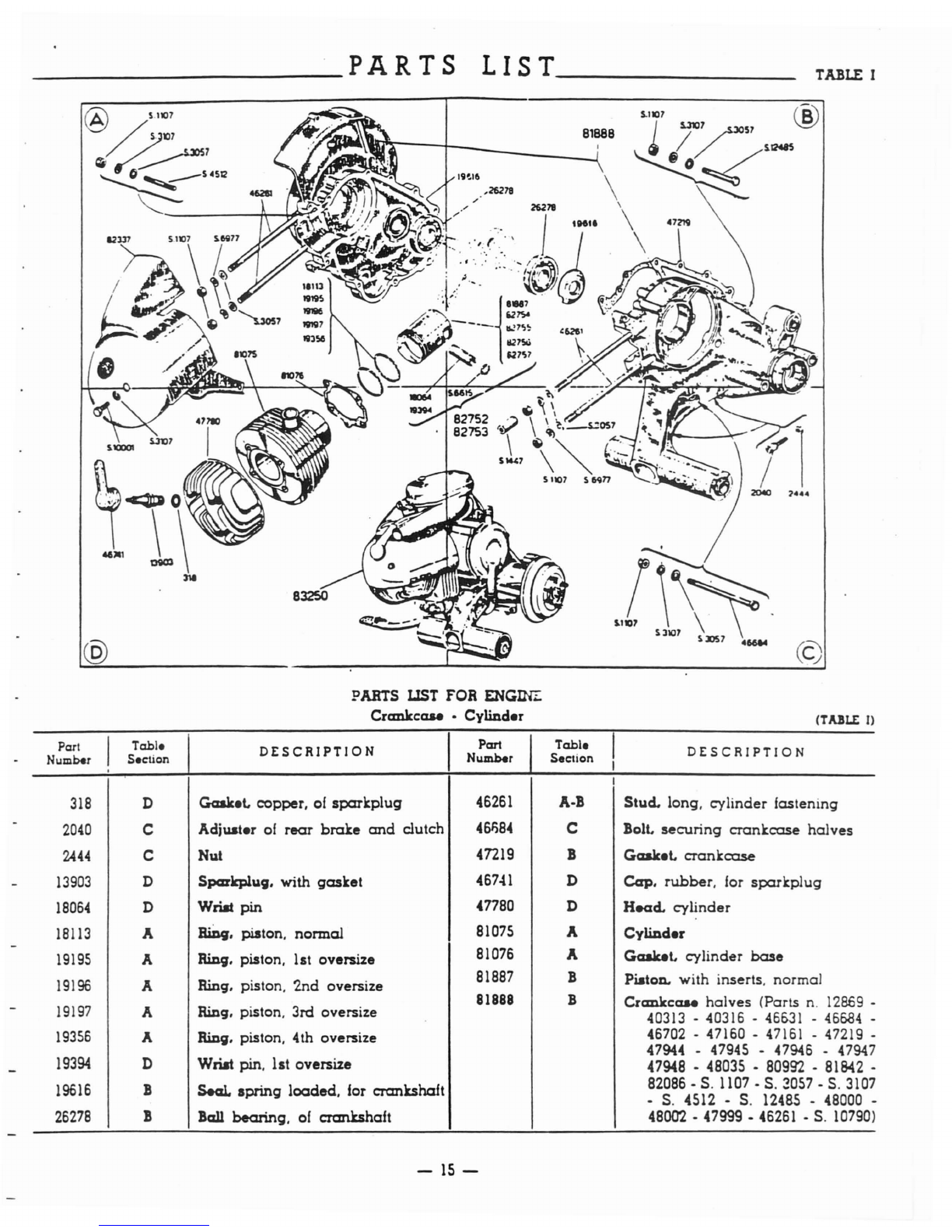
PARTS IJST
fOR
ENG~
Crankcase
-Cylinder
(C)
(ToUU:
l)
Part I
Table
DESCRIPTION
IPart
Table
I
DESCRIPTION
Number Section
Nwnber
Section
,I
I
318
DGaaket. copper,
of
sparkplug
46261
A-B
Stud.
long, cylinder fastening
2040
CAdjuster
of
rear
brake
and
clutch
45$)84
CBolt.
securing
crankcase
halves
2444
C
Nul
47219
BGaalcet.
crankcase
13903
DSparkplug.
with
gasket
.(6741
D
Cap.
rubber.
for
sparkplug
18064
DWriat
pin
"n80
D
Head.
cylinder
18113
A
~.
piston. normal
81075
A
Cylinder
19195
ARing. piston.
1st
oversize
81076
AGaalcet. cylinder
base
19196
ARing. piston.
2nd
oversize
81887
BPiston. with inserts, normal
81888 B
Crankcase
halves
(Parts
n.
12869
-
19197
ARing, piston.
3rd
oversize
40313
.
40316
.
46&31
-
46684
-
19356
ARing. piston.
4th
oversize
46702
.
47160
-
47161
-
47219
.
47944
.
47945
-
47946
-
47947
19394
D
Wn.t
pin, lst oversize
47948
-
48035
-
80992
.
81842
-
19616
B
Seal.
spring
loaded,
for crankshaft
82086
-
S.
1107.
S.
~057
-
S.
3107
-
S.
,(512
-
S.
12485
.
48000
-
26278
BBall
bearing.
of
crankshaft
48002
.
47999
-
46261
.
S.
10790)
-
15-
Part. li.t
for
eaqiDe -Crankr:a.e •Cylinder •Continued
Part Table I
DESCRIPTION
Part
Table
I
DESCRIPTION
Number Section Number Section
82237
AHood. cooling
S.
1107
A-B-C Nut. for locking
cylinder
head
and
82752
CPiston. with
standard
wrist pin
crankcase
halves
(Parts
n.
180&4
-
81887
-
S.
6611)
S.
3057 A·B·C
Waaher.
plain
82753
CPiston. with wrist pin.
1st
oversize
S.
3107 A·B·C·D
Washer.
spring
(Parts
n.
180&4
-
92754
-
S.
60
11
)S.
1-447
CNut.
spacer,
hood
fixin9
82754
BPiston. with inserts, 1st oversize
S.
4512
A
Stud.
securing
cranxcose.
halves
gz755
BPiston. with inserts. 2nd oversize
S.
6615
CCirc:lip. for locking
gudg~on
pin
82756
BPiston. with inserts, 3rd oversize
S.
6977
A·C
Washer.
spring
S.
10001
D
Screw.
hood
fixing
82757
BPiston. with inserts, 4th oversize S.
12485
BBolt. short,
securing
crCJ'!.ki:ase hal-
83250
DEngine. g.a.
ves
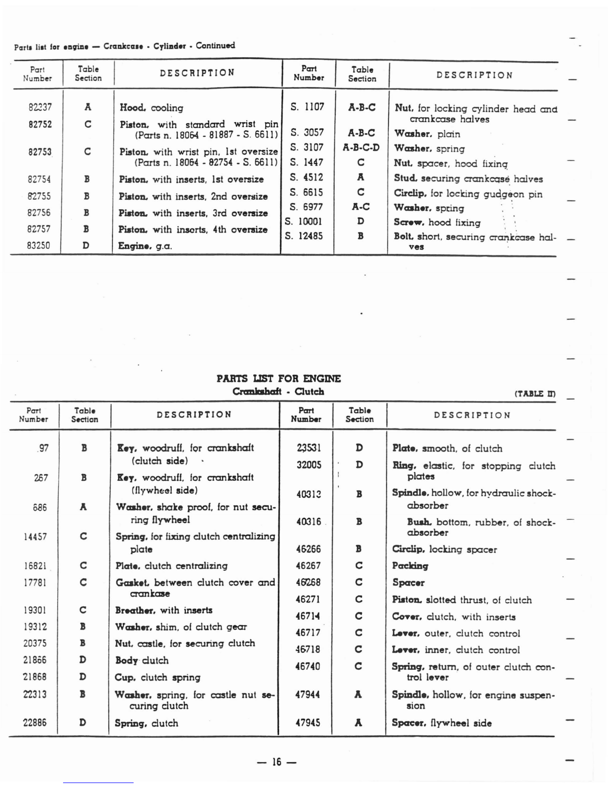
PARTS LIST
FOR
ENGINE
Cnmlrehaft -Clutch
(T.uLE
m
Pan
ITable I
DESCRIPTION
Part I
Table
I
DESCRIPTION
Number
s.ctlon
Number Section
.97
B
X..,.
woodruU, for crankshaft
~53'}
DPlcrte. smooth. of
clutch
(clutch side) 32005 D
RlDq.
elastic. for
stopping
clutch
267
BXey. woodruff, for crankshaft I
plates
(flywhe<!1
side) 40312 BSpindle. hollow, for
hydraulic
shock-
686
AWasher.
shake
proof. for
nut
se<:u-
absorber
ring flywheel 40316 .BBush. bottom,
rubber,
of
shock-
14457
CSpring. for fixing
dutch
centralizing
absorber
plate
4&266
BCirclip. locking
spacer
16821
CPlate. clutch centralizing 46267 C
Packing
17781
CGasket.
between
dutch
cover
and
45'258
C
Spacer
crankaae
46271
CPiston. slotted thrust.
of
clutch
19301
CBreather. with
inserts
467104
C
Co?er.
dutch,
with inserts
19312
B
Washer.
shim.
of
dutch
gear
46717 CLe"er.
outer,
dutch
control
20375
BNut. castle. for
securing
clutch
4&718
C
Le~.
inner,
dutch
control
21856
DBody·
dutch
46740 CSPfiD9. return.
of
outer
dutch
con-
21868
DCup. clutch
spring
trol
lever
22313
B
Washer.
spring, for
castle
nut
se- 47944 A
Spindle.
hollow, for
engine
suspen-
curing
clutch
sian
22886
DSpring.
dutch
47945 A
Spacer.
flywheel
side
-
16-
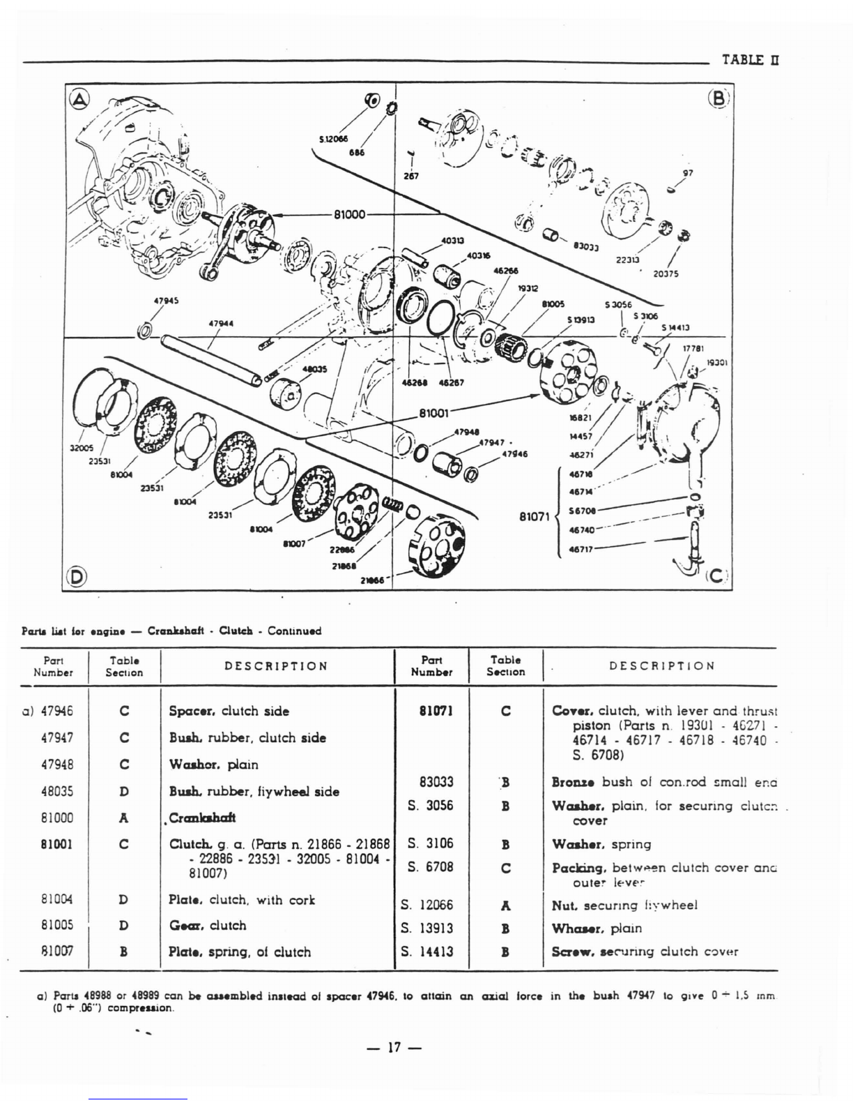
TABLE n
@
46717
Pcuta llat
for
engine
-Crankahcdt •
C!utdl
•
Continued
Part I
Table
I
DESCRIPTION
Part
Table
I·
DESCRIPTION
Number Seclion
Number
Seellon
0)
47946
C
Spacer.
clutch
side
81071 C
Coyer.
clutch. with
lever
and
thru>il
47947
CBush.
rubber.
clutch
side
piston
(Parts
n.
193U
I -
4G271
-
46714
•
46717
-
46718
•
46740
47948
CW
ashor.
~ain
S.
6708)
48035
DBush.
rubber.
fiywheel
side
83033
·.B
Bron1e
bush
of
con.rod
~mall
er.a
S.
3056
B
Washer.
plain.
for
secunng
clute::
81000
A•
Crcmlcsh
aft
cover
81001
CClutch. g.
a.
(Parts n.
21866
-
21868
S.
3106
B
Washer.
spring
•
22886
-
23511
-
32005
-
81004
•
S.
6708
C
Padting.
betw~n
clutch
cover
COG
81007)
outer
IE-Vf'o
81004
DPlale. clutch. with cork
S.
1206£
ANut.
secunng
f:ywheel
81005
I
D
Gear.
clutch
S.
13913
B
Whaaer.
plain
g10D?
BPlate. spring.
of
clutch
S.
14413
B
Scre
••
sec-uring
clutch
C::lver
a)
Parts
48988
or
4B9B9
can
be
auembled
inllead
of
lpacer
47946.
\0
attain
an
axial
lorce
in
the
buah
47947
\0
91ve
0.;-
1.5
mm
(0
+.06") cOlIlpreuion.
-17-

--------------------------------
__
TABLEm
(J;;)/
snw
:D
PARTS LIST FOR ENGINE
Gear
box
•Rear
wh
..
1Dange (TABLE III)
Part I
Table
DESCRIPTION
Part
Table
I
DESCRIPTION
Number Seclion
Number
Section
61
AClip. spring, lor
brake
jaws
12869 B
Screw.
for
dust
cover
2021
ASc:rew. lor joining
brake
drum
to
17821
DSelector.
gear
flange
a)
17B24
CGear. 2nd
speed
2035
B
LiDk.
brake
19H7 CClJ'Clip.
retaining
shoulder
washer
2036
BBolt. for securing
cable
to
brake
a)
18558
C
Washer.
shoulder.
normal.
of
gear
links pinions
2082
BPin. for
rear
brake
links
a)
19611
CG.a:r. 3rd
speed
2098
ASplit pin.
for
locking castle
nut
a)
20321
C
Washer.
shoulder. 1st oversize
2442
ANut.
for
securing
wheel
a)
20322 C
Washer.
shoulder
2nd oversize
7563
ABall
bearing
of
mains
haft
a)
20323 C
Washer.
shoulder
3rd oversize
7884
B
Arm.
rear
brake
control
a)
20324 CWhaMr.
shoulder
4th oversize
7886
A
Pad
23831
ADrum.
rear
brake
a)
Th.
total
axial
plOT
of
the
auembly
·of the 3
gear
pinion.
in
respect
to
their
Hat
mu.l
be
contained
between
.006"
and
.olr.
Shoulri this
play
exceed
.aid
toleraneell. the
nonnal
.houlder
wa.h.r
mu.t
be
replaced
br
another
with
proper
o.e~ize.
--
18-

PcutI llal lor
eniine
-
Gear
box·
Rear wheel ilanve •
ConLlnu~d
MaiDahaft. g.a. (Parts
n.
17821
-
18447
_
18558-
46605
_
47190
_
S.
13815
82085
•
S.
13768)
ParI
Number
25990
46605
46688
46696
46099
46700
46702
46803
47190
a)
48349
81'229
820S(
ITable
Seclicn
A
C
A
A
A
A
B
B
C
C
A
C
DESCRIPTION
Spring. return,
of
brake
jaws
Stem. selector
Ring. locking ball
bearing
Axl..
cam.
of
rear
brake
S.aL
spring
-
loaded
of
mainshaft
Circlip
Duat cover
Deneetor
Bush. guide,
01
selector stem
Gear.
low
speed
Jaw.
rear
brake.
with lining
IPari
Number
a)
82085
82120
S.
1207
S.
2314
S.
3110
bis
S.
3204
S.
~208
S.
13768
Tabl..
Section
D
A
B
A
A
B
B
C
A
DESCRIPTION
Mainahaft
Flange.
female spline, with inserts
Nut.
on
bolt
securing
brake
links
Nut. castle, for
securing
wheel
flange
Washer.
spring,
for
nut
securing
wheel'
Split pin.
on
pin for
brake
links
Split pin. for
cam
axle
Washer.
tab,
on
selector
stem
Waaher.
plain,
for
nul
securing
wheel flange.
a) The
IOlal
axial
play
ol the
auembly
01
the
3
gear
pinion.
in
relpect
to
their
aeal
mlal
be
contained
belwHn
.006"
and
012".
Should thil
play
exc:oed
laid
toleranc
..
,the normal
lhoulder
'Wasber mUlt
be
replacod
by
another
'With
proper
overl11e.
PARTS
LIST
FOR ENGINE
Cuah
gear
•
Kicbtarter
(TABLE:
JV)
Pan
ITable I
DESCRIPTION
Part I
Table
I
DESCRIPTION
Number Section INumber Section
2457
DBoller. for multiple
gear
483«7
CGear. multiple
17887
C
Spring.
of
cuah
drive
48348
C
Gear.
starting
17888
C
Gear.
outer,
of
c:u.sh
drive
81842
ARoller
31157
C
Washer.
plate,
of
cush drive
springs
82086
A
Cage.
roller
bearing
3'2494
DBall
bearing,
01
multiple
gear
82128
BKic:katarter
46618
DLayabaft
83014
COri..... cushion. g.a. (Parts
n.
17887
-
46631
B
Plug
17888
-
311S7
-
48347
-
S.
10776)
'{67'42
CBuJfer. for
starting
sector
S.
1209
DNut. for
securing
layshaft
47160
ARaee. roller
bearing
of
mainshaft
S.
3057
B
Waabar.
plain.
01
kickstarter
47161
A
Washer.
shoulder, roller
bearing
S.
3109
D
Washer.
sprin';l. for
nut
securing
layshalt
47'218
ASpring. return,
of
kickstarter
S.
57'23
ARiTet.
se=U1
ing
pr:Iwl
47226
B
Scre
••
securing
kickstarter
S.
6637
DCirclip. lor locking multiple
gear
47996
DSector. starting, with
parts
47998
-
ball
bearing
S.
S723
S.6721 B
Packing
47998
APcrwl
S.
10776
CBiTet. for
securing
plate
washer
47999
CBlad•• long, for starting
sector
S.
10790
C
Bi
....t. for
securing
blades
.{8000
CBlade. short, for
starting
sector
S.
12824
D
Waaber.
plain,
for
nut
securing
48002
C
Pad.
blades
layahaft
-
19-

________________________________
TABLE
IV
__
82128
@
47996
Sll637
.I
PARTS LIST
FOB
ENGINE
FlTWb
..
l
Magneto
•Fcm
5.1)77'&
{
@
©
(TULE
V)
Part I
Tabl.
I
DESCRIPTION
Part I
Tabl.
I
DESCRIPTION
Number Section Number Section
603
0Screw. for
securing
coils 16416 CBreaker.
with
platinum
point
619
0
Washer.
plain. for
securing
coils 16417 CAxle.
breaker
622
C
Washer.
shim. of
breaker
16418 C
Guaet.
contact
624
CNut 16419 CRiD9.
insulating
16420 CCam
625
CFork
spring
16421
0
Blade
felt.
with
inserts
662
"'-0
TermiDal 46750 0
Condenser
6'74
BCarclip. for flywheel
extraction
46075
...
Cam
2856
BSc:rew. long. for
securing
fan
cas-
46764
...
Cable.
earth.
with
terminal
ing
cover
46766
...
Grommet
2946
B
Scre~.
short. for
securing
fan
cas-
47191
...
Flywh
..
L
with
inserts
(Parts
n.
6562
ing cover •46675 -S.
IOnS)
3213
cSc:rew.
securing
condenser
and
felt 47576 BFcm
blade
47sn
Beo..r. fan
casing
65~
B
Washer.
plain.
of
com
82150
...
Coil
ignition. g.
a.
(Parts
n.
82852 -
1,(501
....
I)
Terminal
4676&
-827(6)
-?f'l
-
Table of contents
Other Allstate Scooter manuals


