Allstate 788.94370 Use and care manual
OPERATING INSTRUCTIONS
AND
PARTS LIST
FOR
OT
SC
OTE
MODEL NUMBER 788.94370
This
is
the
Model
Number
of
your
Allstate
Motor
Scooter.
It
will
be
found
on
a
plate
fastened
to
the
chassis
under
the
fuel
cock.
Always
mention
this
number
when
communicating
with
us
regarding
the
Scooter,
or
when
ordering
repair
parts.
HOW
TO ORDER REPAIR PARTS
All
parts
listed
herein
may
be
ordered
through
any
Sears
retail
or
mail
order
store.
In
ordering
parts
by
mail
from
the
mail
order
store
which
serves
the
territory
in
which
you
live,
Selling
Prices
will
be
furnished
on
request
or
parts
will
be
shipped
at
prevailing
prices
and
you
will
be
billed
accordingly.
WHEN
ORDERING
REPAIR PARTS, ALWAYS GIVE
THE
FOLLOWING INFORMATION:
1.
The
Part
Number
in
this
List.
2.
The
Part
Name
in
this
List.
3.
The
Model
Number
of
the
item.
This
list is
valuable.
It will
assure
your
being
able
to
obtain
proper
parts
selvice
at
all
times.
We
suggest
you
keep
it
with
other
valuable
papers.
ScootelWorks USA Inc.
5709
N.
Ravenswood
Chicago,
IL
60660
ph: 773.271.4242
fx:
773.271.5012
EARS, EB cA
O.


gs to
19ine
ss
of
lders
rpm
wi h
ance
",ind,
scoo-
nor-
f
be
Fig. 1 •
Sun
Motor
Scooter
WARNING
,-----------.'
-'-
Fig. 2 .
location
of
.erial
number
Serial
numbers
are
preceded
by
prefixes:
VMA
1
T,
for
frame;
VMA
1M,
for
engine.
~
on
nbed
gear
seful
that
;ome
from
lrbu-
)wn-
use
stion
form
in
e
in
et
or
he
he
and
)ion
en-
order
to
keep
your
scooter
in
perfect
running
condi-
on
and
not
to
void
the
guarantee,
always
have
your
achine
repaired
at
a
Seras,
Roebuck
and
Co.
Store.
pecial
care
should
be
taken
with
regard
to
the
fuel
ixture
which
should
be
regular
gasoline
and
oil
of
e
make,
grade
and
in
the
amount
prescribed
in
this
ooklet.
Ethyl"
gasoline
should
never
be
used.
Do
not
use
Allstate
compounded
motor
oil
or
other
Praemium
Heavy
Duty
Oil
with
detergents.
The
inexperienced
operator
should
exercise
caution
in
applying
front
wheel
brake,
to
avoid
locking.
Fig. 3 -
Control.
of
Sean
Scoot..r
1.
Gear
chanC)<'
two
>tg"p
with
clutch
control
leve'
.
2.
Front
brake
lever
.
J.
Throttle
con·
trol
grip
-
~.
L'Qht
and
dim-
mer
switch
.S.
Front
brake
jaws.
-
6.
Reor
bra'e
pedal
-
7.
Kic
starter
-
•.
Gear
selec-
tor
-
9.
Reer
brake
jews.
10.
Clutch.
11.
Carburetor,
air
cleaner.
12.
Storter
push
pull
rod
-13_
fuel
cock.
-
14.
Knob
for
locking
tilting
sad-
dle
- 1
S.
Lever
for
removing
engine
flap.
-3-
.
--_.-.
-'-'-'"
,
r----
I
/
\.
;'
----?....,P'""
.---_.
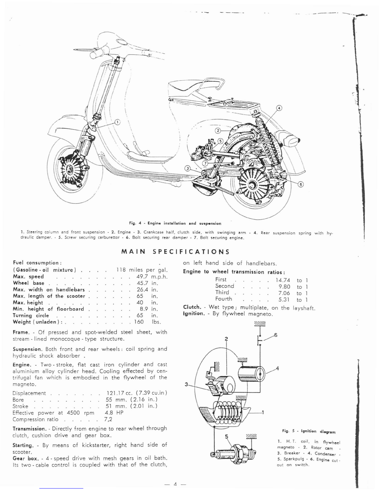
Fig. 4 -
Engin.
installation
and
IUlp.olio"
1. Steering column
and
front
suspension·
2.
Engine·
3.
Crankcase
half.
clutch
side.
with
swinging
arm
.
4.
Rear
suspension
spring
with
hy.
draulic
damper
..
5.
Screw
securing
carburettor
.
6.
Bolt
securing
rear
damper.
7.
Bolt
securing
engine.
MAIN
SPECIFICATIONS
Frame. -
Of
pressed
and
spot-welded
steel
sheet,
with
stream
-
lined
monocoque
-
type
structure.
Suspension.
Both
front
and
rea r
wheels:
coil
spring
and
hydraulic shock
absorber
.
Engine. -Two -
stroke,
flat
cast
iron
cylinder
and
cast
aluminium
alloy
cylinder
head.
Cooling
effected
by
cen-
rifugal
fan
which
is
embodied
in
the
flywheel
of
the
magneto.
Displacemen
121.17
cc.
(7.39
cu .in )
Bore
55
mm.
(2.16
in.)
Stroke
51
mm.
(2.01
in.)
Effective
power
at
4500
rpm
4.8
HP
Compression
ratio
7,2
Transmission. -Directly
from
engine
to
rear
wheel
through
clutch,
cushion
drive
and
gear
box.
Starting. -
By
means
of
kickstarter,
right
hand
side
of
scooter.
Gear
box.
- 4 -
speed
drive
with
mesh
gears
in oil
bath.
I s
two
-
cable
control
is
coupled
with
that
of
the
clutch,
Fill· 5 • IgnltJon
di-vnm
1. H.
T.
coil. in
flywheel
magneto
•
2.
Rotor
cam
3.
Breaker
-
4.
Condenser
.
5.
Sparkpulg
.
6.
Engine
cut-
out
on
switch.
to
1
to
1
to
1
to
1
layshaft.
3
on
left
hand
side
of
handlebars.
Engine
to
wheel
transmission
ratios:
First
14.74
Second
9.80
Third
7.06
Fourth
5.31
Clutch.
-
Wet
type;
multiplate,
on
the
Ignition.
-
By
flywheel
magneto.
118
miles
per
gal.
49.7
m.p.h.
45.7
in.
26.4
in.
65
in.
40
in.
8.9
in.
65
in.
160
Ibs.
Fuel
consumption:
(Gasoline -oil
mixture)
Max.
speed
Wheel
base
.
Max.
width
on
handlebars
Max.
length
of
the
scooter
Mu.
height
Min.
height
of
floorboard
Turning circle
Weight
(unladen)
:
-4-

F
,\
I
r
Lubrication. -
By
the
oil in
fuel
mixture
for
piston,
cylinder,
wrist
pin,
can.
rod,
crankshaft,
main
bea-
ring
flywheel
side.
The
clutch,
the
main
bearing
clutch
-
side
and
gear
box
operate
in oil
bath.
Carburettor.
-
With
float
-
chamber
(see
fig.
11).
Air
goes
to
the
car-
burettor
through
a
large
silencing
chamber
with
filter
(air
cleaner).
Model
.af
carburet
or:
Dell'Orto
SHB
16/16
-
Venturi
16
mm.
(0."
630)
-
Main
jet
74/100
(0."0291
)
Idler jet
42/100
<0".0163)
-
Air
vent
for
main
jet
140/100
(0."
0550)
-
Mixer
175/100
(0."069)
-
Air
vent
to
idler
jet
130/100
(0."051)
Starter
jet
50/100
(0."0197).
Feeding.
-Fuel
feed
to
the
ca
rbu-
rettor
is
provided
for
by
gravity
(see
fig.
11)
with
gasoline-oil
mixture.
~
Fuel·~nk.
Total
capaciy:
1.5
gals.;
Reserve:
1/4
gal.;
Three
-
way
cock:
"open"
-«
closed"
-«
reserve
".
Muffier. -
Expansion
and
absorption
combined
type.
H
..
ndleb
..
rs. -
Pressure
die
cast
in
light
alloy
and
designed
so
as
to
house
both
headlamp
and
speedometer.
All
the
control
cables
and
electrical
wires
to
this
group
are
con-
cealed
therein.
(See
fig.
3).
Steering
column.
-
The
steering
column
bears
the
hand-
lebars,
clamped
on
its
top
end,
and
the
front
wheel
swinging
hub,
pivoted
at
its
bottom
end
through
a
stub
axle.
Lighting
and
horn.
-
By
flywheel
magneto,
feeding
both
head
lamp
(two
-
beam),
tail
lamp,
horn
and
stop
light
(see
fig.
8).
Brakes. -
Expanding
type
.
Front
brake:
control
lever
on
right
hand
side
of
handle-
bars.
Rear
brake:
control
pedal
on
right
hand
side
of
floor-
board.
The
rear
brake
jaws
are
hinged
on
independent
pivots.
Wheels.
-
Of
pressed
steel
sheet,
intechangeable
and
easily
removable,
since
they
are
assembled
in
an
auto-
mobile
-like
system.
Tires:
dia.
3.50
x
lOin.
Steering
Lock. - A
suitable
security
lock is
arranged
on
the
frame,
near
the
handlebars.
Turn
the
handlebars
to
the
left,
then
rotate
the
key
and
push
inwards,
so
that
it
thrusts
the
sliding
bar
against
the
steering
column.
To
ease
the
insertion
of
the
sliding
bar
into
the
hole
of
the
steering
column,
slightly
turn
the
fig.
6 .
s.rtion
of
engine
1. Air
cleaner
and
carburettor
-
2.
Piston
.
J.
Crankshaft
-
~.
Clueth
S.
Mainshaft
.
6.
Gear
shifter
.
7.
Flywheel
magneto
a.
Kickstarter
9.
Crankcase
half,
clutch
side,
with
swinging
arm.
handlebars
from
the
limit
stop
clockwise.
When
the
hand-
lebars
are
locked
the
key
will
now
spring
back
to
its
original
position
and
can
then
be
withdrawn.
To
release
the
handlebars,
insert
the
key
in
the
lock,
turn
fig.
7 -
S-.:urity
lod,
1.
Normal
position.
2.
Closed
Not.
.The
arrows
indicate
the
operation
to
be
carried
out
for locking
(
J)
and
for
unlocking
(2).
-5-
_.
__
..
_
r-"
.•
0.1
__
""
~
........
,
'-VIII
lllC::
IICIIUICUd(~
in
he normal
position.
The
key
can
be
extracted
from
the lock
even
if
the
handlebars
are
free.
Do
not
lubricate
he
steering
lock.
Central
Stand.
- A
two
-
legged
stand
is
arranged
un-
der
the
floorboard.
A
strong
return
spring
holds
it
in
contact
with
the
floorboard
and
keeps
it
from
vibrating
while
the
scooter
is
being
ridden.
Tool Kit. - 1
box
wrench
(11
-17
-
21
mm.);
2
single
open
-
ended
wrench
(/
-8
mm.);
1
screw
-
driver.
These
hand
tools
are
contained
in aroll
which
is
placed
in
the
tool
box.
Speedometer.
-
The
speedometer
has
its
housing
in
the
middle
of
the
handlebars
and
adds
to
the
perfor-
mance
and
appearance
of
the
scooter.
Accessories
(See
specific
Table
of«
Parts
List
»).
-
On
re-
quest
the
Sears
scooter
can
be
equipped
with
the
spare
wheel
and
bracket,
and
rear
pillion
seat.
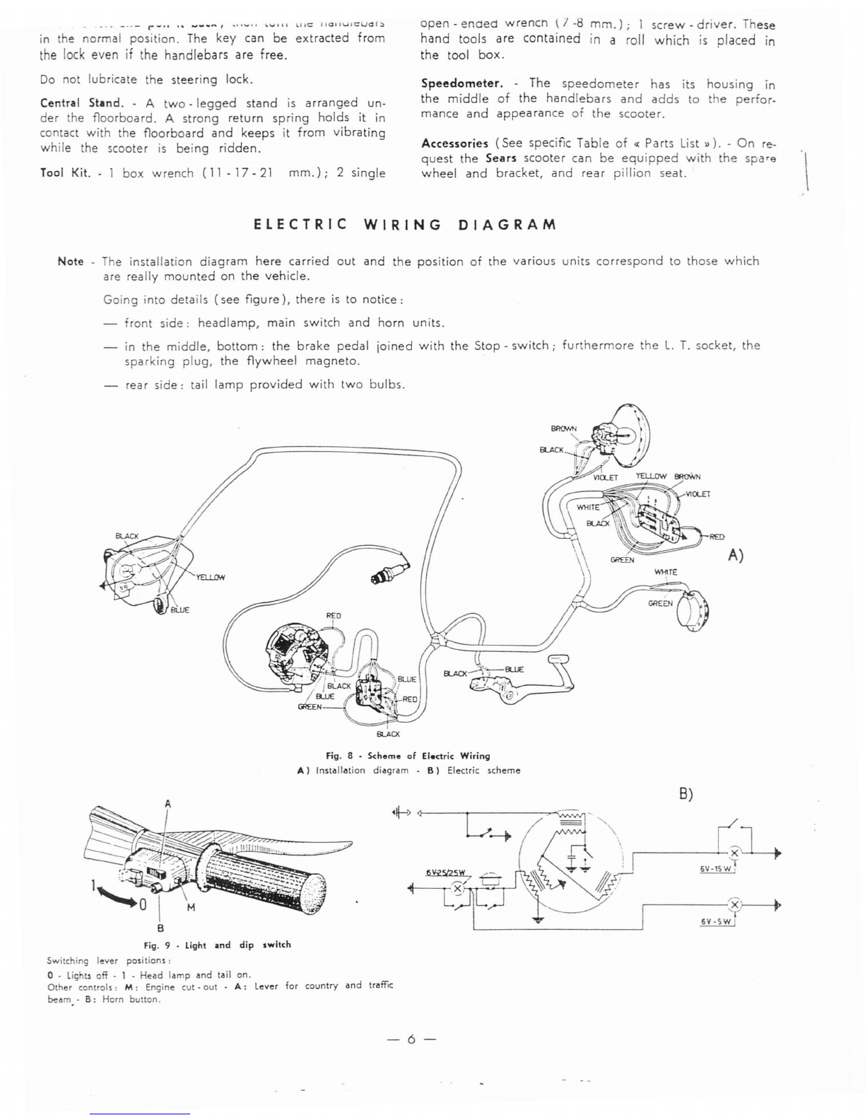
ELECTRIC
WIRING
DIAGRAM
Note -The
installation
diagram
here
carried
out
and
the
position
of
the
various
units
correspond
to
those
which
are
really
mounted
on
the
vehicle.
Going
into
details
(see
figure),
there
is
to
notice:
front
side:
headlamp,
main
switch
and
horn
units.
in
the
middle,
bottom:
the
brake
pedal
joined
with
the
Stop
-
switch;
fur
hermore
the
L.
T.
socket,
the
sparking
plug,
the
flywheel
magneto.
rear
side:
tail
lamp
provided
with
two
bulbs.
A)
8LACX
Fig. 8 • S<:heme
of
Electric
Wiring
A)
Installation
diagram
.
B)
Electric
scheme
B)
Fig. 9 .
light
.nd
dip
switch
Switching
lever
positions:
o -
lights
off • 1 .
Head
lamp
and
tail
on.
Other
controls:
HI:
Engine
cut·
out
-
A:
Lever
for
country
and
traffic
beam.
-
B:
Horn
button.
-6-

OPERATION
Fuel
supply
..
Fuel
mixture,
both
during
and
after
run-
ning
in, should be
composed
of
regular
gasoline and
pure
mineral
oil
SAE
30 at
2%,
i.
e.:
-
~,~
pint
of
oil to 1
'l~
gal-
lons
of
gasoline.
When using pre -
diluted
or
additive
oils,
or
oils
for
out-
board
motors,
mix
'l~
pint
of
oil
per
gal.
Keep the
breather
of
filling
cap clean.
Oil
level.
-Remove the level
screw, on crankcase,
marked
«
OLIO»
as
indicated
on Fig.
20, to check
oil
level
in
gear
box
before
sta
rting
the en-
gine.
The
scooter
standing
upright,
oil should just be
about
to
flow
out;
otherwise
top
up
with
ALLSTATE
REGULAR
S.
A.
E.
30.
Fig.
10
• F
..
ding
circuit
1. Fuel
COC'(
lever:
A)
Reserve.
B)
Open.
C)
Closed
-
2.
Throllie
slide
set
screw·
J.
Idling
adjuster
-
4.
Idling
iet
-
5.
Starter
valve
-
6.
Air
vent
for
idling
ie -7. Air
cleaner
-
8.
Air
vent
for
main
jet -
9.
Starter
jel
-
10.
Float -
11.
Mai:1
jet -
12.
Throllie
slide
-
13.
Inlet
port
-
14.
Transfer
ports
.
15.
Exhaust
duct.
Fig.
11
-
Oper.tiona
to corry
out
for
rtarting
the
engine
·1
~
.\
A:
open
the
fuel
cock.
B:
seleCI •
neutral.
-
c:
operate
starter.
push
pull
rod
(with
cold
engine)
0:
throllie
centrol
grip
in
idling
pNition
-
E:
depr~..
the
kickst.rter
.nd
turn
grip
cD.
by
short
strokes.
-7-
Running.
in. -
Important
rules
to
be
followed
while
run-
ning
-
in
(600
miles):
Do
not
insist
by
fully
opening
out
the
throttle.
Change
oil
in
the
gear
box
and
check
that
nuts
and
bolts
are
not
slack
after
the
first
600
miles.
Starting
..
Open
the
fuel
valve,
put
the
gear
box
in
neutral
and
slightly
open
the
throttle
in
slow
running
position,
kick
the
starting
lever.
With cold
engine,
operate
starter
push
pull
rod.
Push
said
rod
back
as
soon
as
the
engine
fires.
See
Fig.
10;
note
the
three
positions
of
the
fuel
valve:
open,
closed,
reserve.
Clution.
-Do
not
open
throttle
wide
when
releasing
clutch.
In
case
of
starting
troubles,
due
to
engine
being
flooded
(unvaporized
fuel
mixture
has
reached
the
cylinder
and
combustion
becomes
therefore
very
difficult),
proceed
according
to
either
one
of
the
following
methods:
a)
Push -
start
the
scooter:
shift
into
second
gear,
de-
clutch
and
push
the
machine;
quickly
release
the
clutch
lever
and
pull
it
back
as
soon
as
the
engine
starts.
b)
Close
the
fuel
cock,
remove
the
spark
plug
and
rotate
the
engine
by
means
of
the
kickstarter.
Wipe
the
plug
dry
and
replace.
Open
the
fuel
cock
and
kick
the
starting
lever.
For
access
to
the
engine
and
remove
the
spuk.
plug,
rotate
the
lever
fig. 3 - n.
14,
then
take
off
the
engine
flap.
Extract
the
spark.
plug,
using
the
box
wrench.
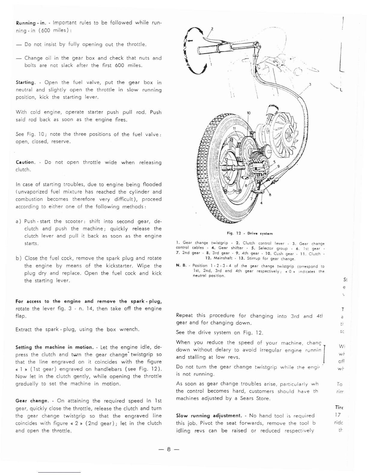
Fig.
12
-
Drive
system
I.
Gear
change
twistgrip
.
2.
Clutch
control
lever
-
3.
GeO'
change
control
cables
-
...
Gear
shifter
-
S.
Sele<tor
group
-
6.
I H
gear
7.
2nd
gear
-
8.
3rd
gear·
9.
4th
gear
-
10.
Cush
gear.
11.
Clutch
_
12.
Mainshaft
-
13.
Stirrup
for
gear
change.
N. B. -
Position
I - 2 - 3 -
<I
of
the
gear
change
twistgrip
correspond
to
1
st,
2nd.
3rd
and
4th
gear
respe<tively;
<0>
Indicates
the
neutrlll position.
Repeat
this
procedure
for
changing
into
3rd
and
4tl
gear
and
for
changing
down.
See
the
drive
system
on
Fig.
12.
l
S(
e
T
a
sc
Slow
running
adjustment.
-
No
hand
tool
is
requi
red
this
job.
Pivot
the
seat
forwards,
remove
the
tool b
idling
revs
can
be
raised
or
reduced
respec
ively
Do
not
turn
the
gear
change
twistgrip
while
the
engi'
is
not
running.
As
soon
as
gear
change
troubles
arise,
particularly
wh
the
control
becomes
hard,
customers
should
have
th
machines
adjusted
by
a
Sears
Store.
Setting
the
machine
in
motion
..
Let
the
engine
idle,
de-
press
the
clutch
and
tum
the
gear
change'
twistgrip
so
that
the
line
engraved
on
it
coincides
with
the
figure
"1,,
(1st
gear)
engraved
on
handlebars
(see
Fig.
12).
Now
let
in
the
clutch
gently,
while
opening
the
throttle
gradually
to
set
the
machine
in
motion.
Gear
change.
-
On
attaining
the
required
speed
in 1st
gear,
quickly
close
the
throttle,
release
the
clutch
and
turn
the
gear
change
twistgrip
so
that
the
engraved
line
coincides
with
figure"
2"
(2nd
gear);
let
in
the
clutch
and
open
the
throttle.
When
you
reduce
the
speed
of
your
machine,
down
without
delary
to
avoid
irregular
engine
and
stalling
at
low
revs.
chane
,uooi~
)
W,
wI-
on
wI-
To
rirr
Tire
17
ridc
tl-
-8-

simply
tightening
or
slackening
the
adjuster
screw
..
A
)}
fig. 13
(i.
e.,
n. 2, Fig.
10).
This
screw
controls
the
throttle
slide
valve.
On
the
carburettor
body
is
a
spring
-
loaded
screw
("
C
})
fig. 13,
i.
e.,
n. 3fig.
10)
that
controls
the
flow
of
car-
burettor
air
through
the
duct
from
the
idling
jet,
and
consequently
the
idling
revs.
We
recommend
that
custo-
mers
refrain
from
re -
setting
this
screw
(and
the
set
screw"
B
",
fig.
13,
provided
for
adjusting
the
throttle
cable
play)
unless
absolutely
necessary
or
during
di-
smantling
and
re -
asembling
operations
that
should,
any-
way,
be
entrusted
to a
Sea
rs
Store.
- 9 -
.\
Ii
(
front)
wh
••
1
Fig.
'4
.
Dismantling
th.
I
ii'
/
I~
;./
----_._------
o
o
~.
When
aflat tire
is
to
be
replaced,
unscrew
the
five
nuts
which
secure
the
wheel
to
its
flange,
pull
wheel
sideways
off
the
studs
(see
Fig. 14 L
repai
rit
or
replace
with
spa
re
wheel.
Tire pressure
should
be
22,5
7
23,5
psi
on
rear
wheel,
17
.7
18 psi
on
front
wheel.
If
the
scooter
is
ordinarily
ridden
by
both
driver
and
passenger,
the
pressure
of
the
rear
tire
should
be
33
7
35,5
psi.
Fig.
13
-
Acce.s
to
cilrburettor
~nd
ilir
d
••
ner
lillY_
To
remove
he
tube,
first
deflate,
then
separate
the
wheel
rims
by
unscrewing
the
nuts
which
join
them
(see
Fig.
15).
Tires. -The
wheels
are
interchangeable,
i.
e.,
they
can
be
assembled
either
in
front
or
rear,
provided
of
course
that
hey
are
inflated
to
pressures
respectively
hereunder
pre-
scribed.
Stopping
the
engine.
Select
in "
neutral
)},
then
push
the
earthing
button.
This will
leave
the
cylinder
full
of
fuel
vapours,
and
the
next
start
will
be
much
easier.

Fig.
15
.
Removing
the
inner
tube
Brake
adjustment.
-Brakes
are
properly
adjusted
if:
the
wheel
rotates
freely
when
respectively
control le-
ver
or
pedal
are
in
resting
position;
the
braking
action starts as
soon
as
respective
con-
trols
are
operated.
Fill.
16
-Brolce
adjustment
These conditions
are
achieved
adjusting
the
cables
by
means
of
screws
indicated
with
an
arrow
in
Fig. 16.
Adjustment
of
clutch
control.
-
Adjustment
of
clutch con-
trols
is
achieved
operating
on
adjusting
nut
(a),
screwed
to
the
engine
sti
rrup
(see
Fig.
17).
The
cable
is
to
be
tensioned
or
loosened,
as
the
case
may
be
so
that
c'ontrol
lever,
on
handlebars,
makes
a
stroke
of 2mm.
(0.078")
before
lever
(b),
on
engine
starts
moving.
Wrong
play
in
the
control
may
cause
the
clutch
plates
burning
out
even
in
normal
running
conditions.
Fill·
17
•
Adjustment
of
clutch
contTol
a
MAINTENANCE
Cleaning
the
scooter.
-
Brushing
kerosene
and
wiping
dry
clean rags
is
advisable
for
external
cleaning
of
engine.
All
painted
surfaces
should
be
washed
with
water,
rinsed
by
means
of
a
sponge
and
wiped
dry
with
a
chamois.
Do
not
use
kerosene
on
such
surfaces,
since
it
damages
paint
and
turns
it
dull.
If
necessary,
blow
the
head
lamp
reflector
clean
or
wipe
off
dust
with a
very
soft
feather.
Do
not
use
acloth
and
keep
your
fingers
off reflector
surfaces.
Before
setting
the
mllchine
in
motion,
(if
it
has
been
delivered
directly
to
the
customer
by
the
Factory)
check
oil level in
gear
box
by
unscrewing
the
level
screw
mar-
ked
«
OLIO,.
from
the
crankcase
(see
Fig.
20).
The
scoo-
ter
standing
upright,
oil'
should
just
be
about
to
flow
out.
After
the
first
600
miles.
-
Replace
oil in
the
gear
box
by
the
procedure
as
explained
in
the
lubrication
chart,
page
12.
The
crankcase
can
be
drained
through
the
hole
indicated
in Fig.
20.
\.
I
-10-

Every
2.500
miles:
--
I
1)
Check
oil
level
in
the
gear
box
(see
on
pages
10-
12)
.
2)
-
Grease
all joints
on
the
brake
controls
and
the
gear
shifter.
3)
.
Clean
the
sparkplug
electrodes
with
very
fine
emery
cloth
or
suitable
files,
and
adjust
the
gap
to
0.6
mm.
(0.023"
).
Inspect
the
insulation
material
of
sparkplug;
re-
place
the
latter
if
the
porcelain
is
cracked.
Wash
with
neat
gasoline.
Use
the
sparkplug
type
Marelli
CW
240
N;
Bosch
W
240
T
1;
Champion
L
86;
AC
42
F.
Important:
using
the
proper
type
of
sparkplug
will
eliminate
many
engine
troubles.
4)
-Pivot
the
seat
forwards,
remove
the
tool
box
and
the
choke
control
cable,
then
dismount
the
fuel
tap
rod
(fig.
13, D -
E);
next
unscrew
the
wing
-
nuts
«F
J)
(fig.
13)
and
remove
air
cleaner.
Extract
the
filter,
wash
in
gasoline
and
if
possible
air
blast
dry.
5)
-
Remove
the
rubber
plug
of
front
suspension
and
refill
·with
grease
the
concerning
housing.
6)
-
Clean
the
lubricators
on
front
wheel
hub
and
refill
them
by
means
of
a
grease
gun.
N.
B.
-All
operations
indicated
hereunder
should
be
carried
out
by
aSEARS
store.
7)
-
Lubricate
the
speedometer
drive
pinion
and
flex
drive.
8)
-
Decarbonize
the
engine
as
explained
hereunder.
Remove
the
carburettor
(screw
n.
5,
fig.
4),
the
rear
wheel,
the
muffler,
release
the
rear
damper
unit
(n.
6,
fig.
4).
then
rotate
the
engine
downwards:
remove
the
cooling
hood,
the
cylinder
head
and
the
cylinder
(see
Fig.
18).
Decarbonize
the
piston
crown
and
the
cylinder
ports
from
all
carbon
de-
posits.
Decarbonize
the
inner
side
of
the
cylinder
head.
Carefully
clear
the
cylinder
carbon
deposits.
Heat
the
exhaust
pipe
of
the
muffler
and
clean
it
either
by
scraping
internally
with
a
hooked
wire
or
blowing
air
through
from
the
other
orifice;
in
both
cases
the
muffler
should
be
held
so
that
the
exhaust
pipe
is
turned
downwards.
Fig.
19
•
Breaker
points
A)
Max.
gap
of
breaker
points
cA.
should
be
0.011".0.019"
Every
5.000
miles:
3)
Change
the
oil in
the
gear
box,
as
stated
on
page
12.
4)
-
Grease
the
felt
wich
lubricates
the
cam
of
flywheel
magneto
(by
a
Sea
rs
Store).
In
case
of
shock
-
absorber
troubles,
overhaul
or
simply
clean
the
assembly
and
change
oil.
These
operations
should
be
carried
out
by
your
SEARS
store.
Fig. 18 •
Cleaning
the
cylinder
heed,
cylinder
and
piston
Clean
the
breaker
points.
In
order
to
avoid
ignition
troubles
or
abnormal
running,
have
the
breaker
points
adjusted
in a
Sears
store;
the
gap
should
not
be
more
than
0.011"-0.019"
(see
Fig.
19)
and
the
points
should
begin
to
open
when
the
current
in
the
primary
ignition
circuit
has
attained
its
peak
value.
Grease
the
control
cables.
1)
-
2)
-
I
11....
Disuse:
1)
In
such
a
case,
cleaning
the
scooter
throughly
is
advisable.
2)
-With
engine
not
running
remove
the
spark
-
plug,
next
introduce
10
-"-
15 cc.
of
Allstate
-
Regulu
Oil
SAE
30
or
Allstate
Outboard
Motor
Oil
through
the
threaded
hole
of
the
latter.
Then
operate
the
kickstarter
three
or
four
times.
3)
-Rest
the
floorboard
on
two
wooden
blocks
in
order
to
take
the
weight
off
the
tyres.
4)
-Drain all
fuel
from
both
tank
and
carburettor.
5)
-
Grease
all
unpainted
metal
parts.
-
11-

LUBRICATION
CHART
PAlT
TO
s.e
OPERATION
T I
III
E
TYPf
OF
LUBlICANT
LUBllCATtD
Engine Mix
gasoline
with
the
following
amount
At
each
refilling
of
the
fuel
Non
-
detergent
SAE
30
of
lubricating
oil:
tank.
MOTOR
Oil
- %
pint
of
oil to 1
y~
gall.
of
gasoline.
N.
B.
-
With
pre-diluted
or
additive
oils,
mix
%
pint
of
oil to
each
gallon
of
gasoline.
Gear
Box
Warm
up
the
engine
and
drain
off
oil.
After
the
fi
rst
600
miles
Allstate
Regular
SAE
30.
Pour
some
fresh
oil in
and
run
the
en-
and
every
5000
miles.
gine
for
a
few
seconds.
Flush
and
refill
with
new
oil
(about
8.5
oz.).
Refill
with
new
oil
to
oil
level
hole.
Every
5000
miles.
Front
wheel
hub
Speedometer
lubricate
with
grease
gun.
Every
2500
miles.
High
Pressure
Chassis.
flex
drive
and
pinion
Joints
on
brake
Grease.
Every
2500
miles.
Allstate
all -
purpose
controls
Gear
lubricator
~AE
140.
Ratchet
qua-
Grease.
Every
2500
miles.
Allstate
all -
purpose
drant
of
gear
Gear
lubricator
SAE
140.
shifter
Control
cables
Clean
and
lubricate.
Every
5000
miles.
Allstate
all -
purpose
Gear
lubricator
SAE
140.
Felt
of
flywheel
Small
spot
of
grease
on
the
felt.
Every
5000
miles.
Allstate
Bearing
Grease.
cam
Shock-a
bsorbe
rs
Change
oil.
Only
when
the
shock
-
ab-
Allstate
Shock
Absorber
sorber
is
out
of
order.
Fluid.
ENGINE
LUBRICATED
BY
MIXTURE
ALLSTATE
REGULAR
SAE
30
/.
OR
ALLSTATE
OUTBOARP
M;;OR
~i
~~
Fig.
20
-
lubrication
scheme
1.
Filling
hole
-
2.
Draining
hole
-
12-
HIGH
PRESSURE
CHASSIS
GREASE
LOCATING
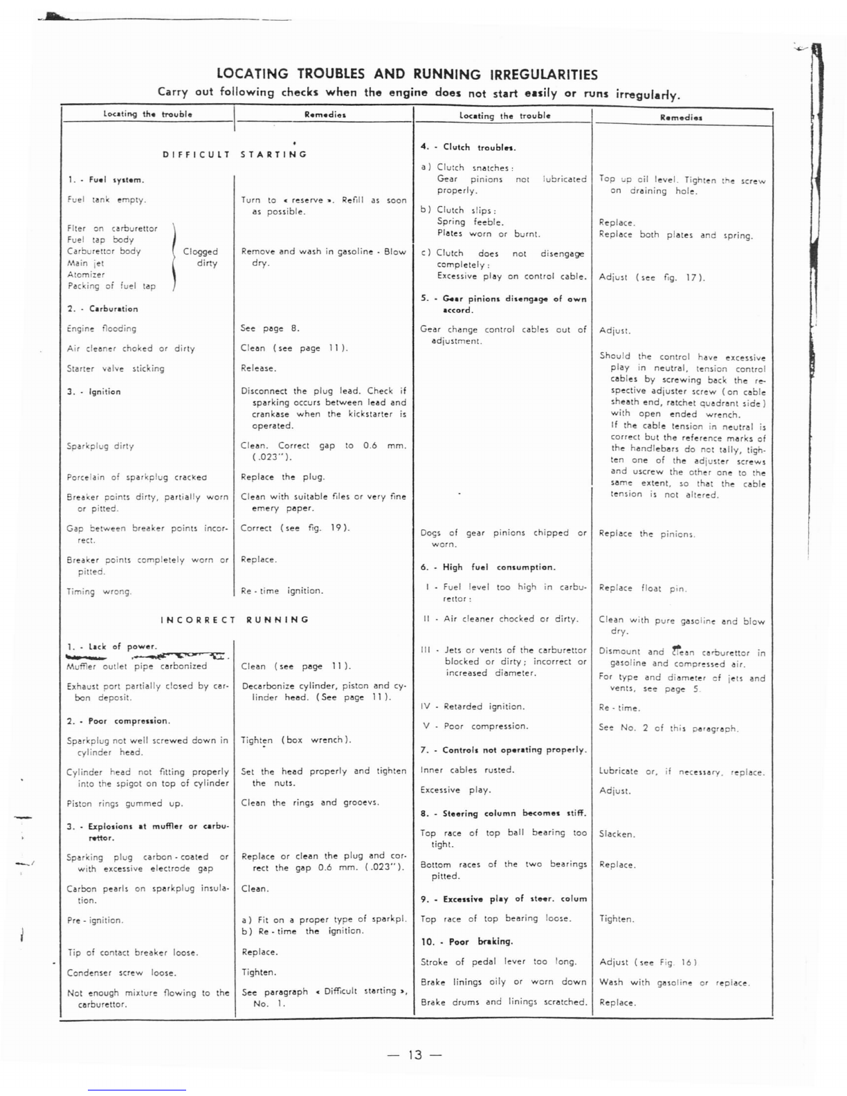
TROUBLES
AND
RUNNING IRREGULARITIES
Carry
out
following
checks
when
the
engine
does
not
start
easily
or
runs
irregulany.
louting
the
lToubl.
I
Remedies
louting
the
troubl.
Remedie.
1------.:..------
------------I-----.:..::.=..:~~....:.--.:.~---I-----------_l
4
..
Clutch
troubln.
DIFFICULT
STARTING
c)
Clutch
does
not
disengage
completely:
Excessive
play
on
control
cable.
Adjust
(see
fig.
17).
Fuel
tanl<
empty.
Flter
on
c.roureltor
Fuel
tap
body
Carbureltor
body
Main
jet
Atomizer
Pac
ing
of
fuel
tap
2.
-
Cubuntion
Clogged
dirty
Turn
to
c
reserve
-,
Ref.1I
as
soon
as
possible.
Remove
and
wash
in
gasoline·
Blow
dry.
a)
Clutch
snatches:
Gear
pinions
not
lubricated
properly.
b)
Clutch
slips:
Spring
feeble.
Plates
worn
or
burnt.
s.
-
c..r
pinions
disenCJ-I94
of
own
accord.
Replace.
Replace
both
plates
and
spring.
tngine
flooding
Air
c1e.ner
choked
or
dirty
Starter
valve
sticking
3.
-
Ignition
Spar
plug
dirty
Porcelain
of
sparkplug
crackee
Bre.ker
points
dirty.
partially
worn
or
pilted.
See
page
B.
Clean
(see
page
II).
Release.
Disconnect
the
plug
lead.
Check
if
sparking
occurs
between
lead
and
crankase
when
the
kickstarter
is
operated.
Clean.
Correct
gap
to
0.6
mm.
(.023·'
).
Replace
the
plug.
Clean
with
suitable
f,les
or
very
fine
emery
paper.
Gear
change
control
cables
out
of
adjustment.
Adjust.
Should
the
control
have
excessive
play
in
neutral,
tension
control
cables
by
screwing
back
the
re-
spective
adjuster
screw
(on
coble
sheath
end,
ratchet
quadrant
side)
with
open
ended
wrench.
If
the
cable
tension
in
neutral
is
correct
but
the
reference
marks
of
the
handlebars
do
not
tally,
tigh-
ten
one
of
the
adjuster
screws
and
uscrew
the
othe
r
one
to
the
same
extent,
so
that
the
cable
tension
is
not
altered.
Gap
between
breaker
points
incor-
Correct
(see
fig.
19).
reet.
Breaker
points
completely
worn
or
Replace.
pilted.
Do<;s
of
gear
pinions
chipped
or
Replace
the
pinions.
worn.
6.
High
fuel
consumption_
Timing
wrong.
Re·
time
ignition.
I
Fuel
level
too
high
in
carbu-
Replace
float
pin.
rettar:
INCORRECT
1. .Lick
of
power.
t
LL
.~"''''''''''~fC)O:>r'-:I-u.:~
_
Mu
er
outlet
pipe
carbonized
Exhaust
port
partially
closed
by
car-
bon
deposit.
RUNNING
Clean
(see
page
11 ).
Decarbonize
cylinder,
piston
and
cy-
linder
head.
(See
page
11).
II
Air
cleaner
chocked
or
dirty.
III
Jets
or
vents
of
the
carburettor
blocked
or
dirty;
incorrect
or
increased
diameter.
IV
Retarded
ignition.
Clean
with
pure
gasoline
and
blow
dry.
Dismount
and
"e~n
cerburettor
in
gasoline
and
compressed
air.
For
type
and
diameter
of
jets
and
vents.
see
page
5
Re
-
time.
2
.•
Poor
comprenion.
Sparkplug
not
well
screwed
down
in
Tight:n
(box
wrench).
cylinder
head.
V
Poor
compression.
7.
Controls
not
operlting
properly.
See
No.
2
of
his
paragraph.
Cylinder
head
not
fitting
properly
into
the
spigot
on
top
of
cylinder
Piston
rings
gummed
up.
Set
the
head
properly
and
tighten
the
nuts.
Clean
the
rings
and
grooevs.
Inner
cables
rusted_
Excessive
play.
8
.•
Steering
column
b-e<omes
1tiff.
Lubricate
or,
if
ne"
..
ary.
replace.
Adjust.
3
.•
Explosions
at
muffler
or
carbu.
rettor.
Top
race
of
top
ball
bearing
lOO
Slacken.
tight.
Sparl<ing
plug
carbon
-
coated
with
excessive
electrode
gap
or
Replace
or
clean
the
plug
and
cor·
rect
the
gap
0.6
mm.
(.023··).
Bottom
races
of
the
two
bearings
pitted.
Replace.
Carbon
pearls
on
sparkplug
insula-
Clean.
tion.
9
.•
Excessive
plly
of
steer.
cofum
Pre·
ignition.
Tip
of
contact
breaker
loose.
Condenser
screw
loose_
a)
Fit
on
a
proper
type
of
sparkp!.
Top
race
of
top
bearing
loose.
b)
Re·
time
the
ignition.
10
.•
Poor
braking.
Replace.
Stroke
of
pedal
lever
too
long.
Tighten.
Tighten.
Adjust
(see
Fig.
16)
Not
enough
mixture
flowing
to
the
carburettor.
See
paragraph
cDifficult
starting"
No.1.
Brake
linings
oily
or
worn
down
Wash
with
gasoline
or
replace.
Brake
drums
and
linings
scratched.
Replace.
-
13-
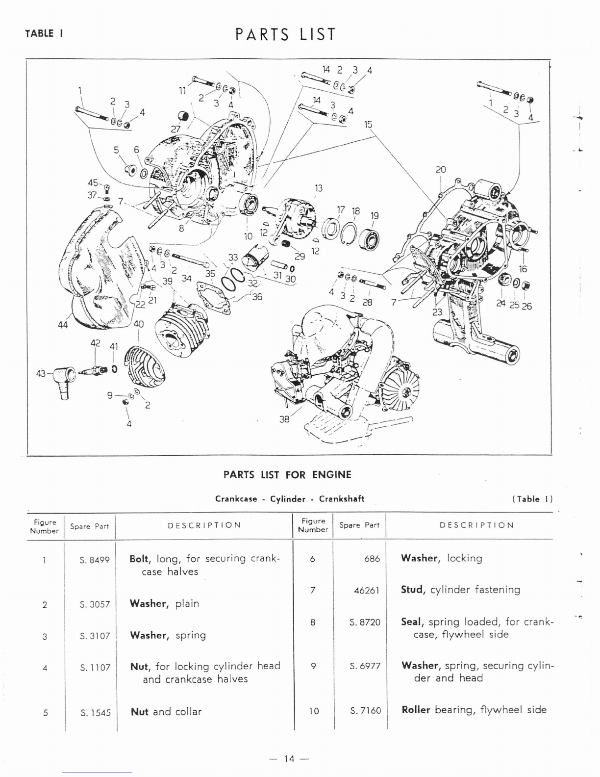
TABLE
I
PARTS
LIST
14
2 3 4
"~
14
3
~
, 4
~
PARTS
LIST
FOR
ENGINE
Crankcase -
Cylinder
-Crankshaft
20
(Table
I)
i
-...
Figure
I I
Number
Spare
Part
S.8499 1
DESCRIPTION
Bolt,
long,
for
securing
crank-
case
halves
I
Figure
I I
Number
Spare
Part
6
686
DESCRIPTION
Washer,
locking
2
3
4
5
S.
3057
S.3107
S.1107
S.1545
Washer,
plain
Washer,
spring
Nut,
for
locking
cylinder
head
and
crankcase
halves
Nut
and
collar
7
8
9
10
46261
S.
8720
S.6977
S.7160
Stud,
cylinder
fastening
Seal,
spring
loaded,
for
crank-
case,
flywheel
side
Washer,
spring,
securing
cylin-
der
and
head
Roller
bearing,
flywheel
side
-
14-

12
267,
Key
Figu,,, I
Number
I
11
..
,,,
Parr
I
S.8420
'
DESCRIPTION
Bolt,
short,
securi
ng
Li
Gn
r,,,
"
lOA
halves
I
Figure
I
Spare
Part
I
Number
I
17
I
91356
DESCRIPTION
Piston, 1st
o/s,
wrist
pin
(with
parts
Figs.
30
-31 -
33)
.
'-
I
-<-.
'
13
14
15
16
17
18
19
20
21
22
23
24
25
26
27
28
29
30
31
32
111311
S.8421
110699
S.456
S.8731
S.6647
S.7125
110711
2856
110720
S.584
111666
S.1821
S.1510
S.7188
S.4515
a)
93233
S.6615
111307
111308
Crankshaft, g. a.
(with
part.
Fig.
29).
Bolt,
securing
crankcase halves
Crankcase, g. a.
(With
parts
Figs. 1 - 2 - 3 -
4 - 11 - 14 -
20
-34
T.
I;
56
T.
II;
21
T.
III;
34 -
35-
36
T.
VIII).
Stud,
securing
flange
for
jaw
Seal,
spring
loaded,
for
crank-
case,
clutch
side
Circlip
Ball bearing, clutch side
Gasket, crankcase
Screw,
securing
cooling
hood
Spacer,
securing
cooling
hood
Stud,
securing
fuel
inlet
joint
Clutch,
drive
gear
Washer,
plain
Nut,
sec.
drive
gear
Roller cage
Stud
Roller cage
Circlip,
for
locking
wrist
pin
Wrist pin,
normal
Piston,
with
standard
wrist
pin
(with
parts
Figs.
30
-
31
-
33)
.
32
32
32
33
33
33
33
33
34
35
36
37
38
39
40
41
42
43
44
45
91357
91358
91359
110651
91368
91369
91370
91371
S.8419
110710
91324
S.3056
150716
S.3918
111446
318
98753
72843
111734
2946
Piston,
2nd
o/s,
wrist
pin
(with
parts
Figs.
30
-
31
-
33)
.
Piston,
3rd
o/s,
wrist
pin
(with
parts
Figs.
30
-
31
33)
.
Piston,
4th
o/s,
wrist
pin
(with
parts
Figs.
30
-
31
33)
.
Ring,
piston,
normal
Ring,
piston,
1st .
o/s.
Ring,
piston,
2nd
o/s.
Ring,
piston,
3rd
o/s.
Ring,
piston,
4th
o/s.
Bolt,
long
Gasket,
cylinder
base
Cylinder piston g.
a.
(with
part
Fig.
32).
Washer,
securing
cooling
hood
Engine, g. a.
Stud,
securing
exhaust
pipe
Head,
cylinder
Gasket,
copper,
of
sparkplug
Sparkplug,
with
terminal
Cap,
rubber,
for
sparkplug
Hood,
cooling
Screw,
hood
fixing
a)
Con -
rods
and
roller
cages
are
subdivided
in 4
categories.
and
the
category
numbe~
is.
marked
on
every
con
-
rod
and
cage.
Assy:
con
-
rod
with
cage
of
the
same
category.
When
ordenng
roller
cages,
always
indiCaTe
the
wanted
caTegory.
-
15-
26
/
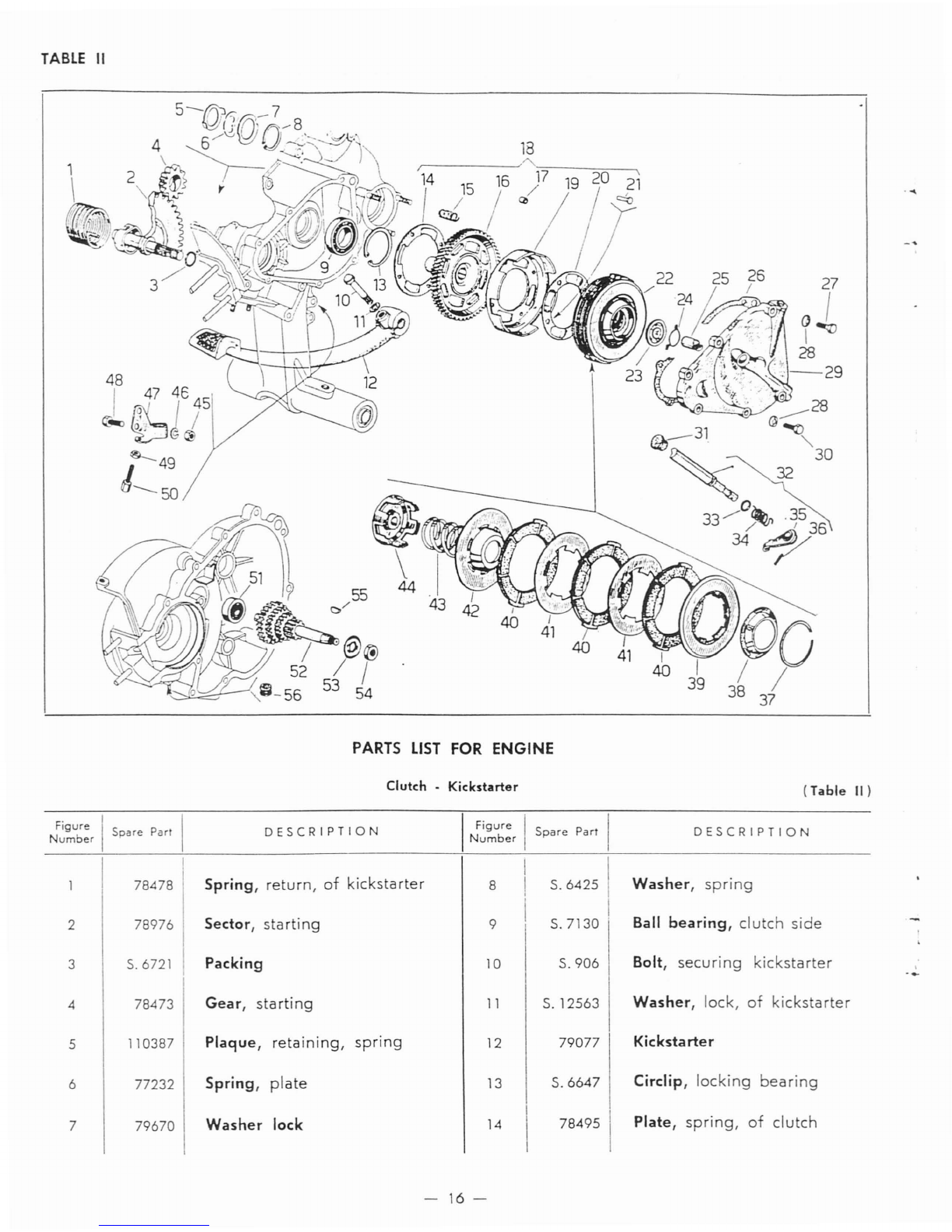
TABLE
II
48
IJ
47
46 45
c~
f!X
I /
~@~
~49
'---50
27
oI
\--V
I
28
:r
.
:-29
~
.....
PARTS
LIST
FOR
ENGINE
Clutch
-
Kickstarter
(Table
II)
~~~u~:r
I
Spare
Part
I
DESCRIPTION
I
Figure
I
Spare
ParI
I
DESCRIPTION
Number
78478 Spring,
return,
of
kickstarter
8
S.6425
1Washer,
spring
I
278976 Sector,
starting
9
S.7130
.Ball
bearing,
clutch
side
3S.6721 Packing
10
S.906
Bolt, securi
ng
kickstarter
,
-.-
478473 Gear,
starting
11
S.12563
Washer,
lock,
of
kickstarter
5110387 Plaque,
retaining,
spring
12
79077 Kickstarter
677232 Spring,
plate
13
S.6647
Circlip,
locking
bearing
779670 Washer lock
14
78495\
Plate,
spring,
of
clutch
-
16-
.......
,'
Figure
I
Nb
Spare
Part
urn
er
15
78484
16
110921 t
DESCRIPTION
Spring, clutch
Gear, clutch
I
35 I
36
Spare
Parr
78450
S.8818
DESCRIPTION
Arm,
actuating
clutch
Pin,
actuating
arm
~.
17
18
19
20
21
22
23
24
25
26
27
28
29
30
31
32
33
34
78594
110670
110669
110668
S.5772
150514
16821
14457
2/78453
79002
S.14413
S.7631
79083
S.12281
78586
78959
S.6706
78452
Spacer
Spring gear
g.
a.
(With
parts
Figs. 14 -15 -
16 - 17 - 19 -20 -
21
).
Body clutch
Plate,
spring,
of
clutch
Rivet
Clutch,
g.
a.
(With
parts
Figs.
37
-
38
-
39
-
40
-
41
-
42
-
43
-
44).
Plate, clutch centralizing
Spring,
for
fixing centralizing
plate
Thruster, clutch
Gasket,
between
clutch
cover
and
crankcase
Screw,
securing
clutch
cover
Washer,
spring
Cover, clutch
Bolt,
securing
clutch
cover
Plug,
actuating
arm
clutch
Arm,
actuating
clutch, g. a.
(With
parts
Figs. 35 -
36).
Washer,
actuating
arm,
clutch
Spring,
actuating
arm, clutch
37
38
39
40
41
42
43
44
45
46
47
48
49
50
51
52
53
54
55
56
79474
150508
79476
79399
79478
79469
112390
79497
S.1107
S.3107
79001
S.12488
S.1205
90527
S.
7035
112377
S.1822
S.1508
S.11753
87685
Ring,
spring,
for
stopping
clutch
plates
Ring, oil
container
Plate,
outer,
of
clutch
Plate, clutch,
with
linings
Plate,
driven,
of
clutch
Plate,
inner,
of
clutch
Spring, clutch
Clutch
case,
inner
Nut,
securing
bracket
Washer,
securing
bracket
Bracket,
supporting
adjuster
of
clutch
Bolt,
securing
bracket
Nut,
setting
clutch
Screw,
setting
clutch
Ball
bearing,
of
multiple
gear
Gear,
multiple
Washer, locking clutch
Nut,
retaining
clutch
Key,
retaining
clutch
Plug,
for
hole
crankcase,
side
flywheel
magneto
-
17-
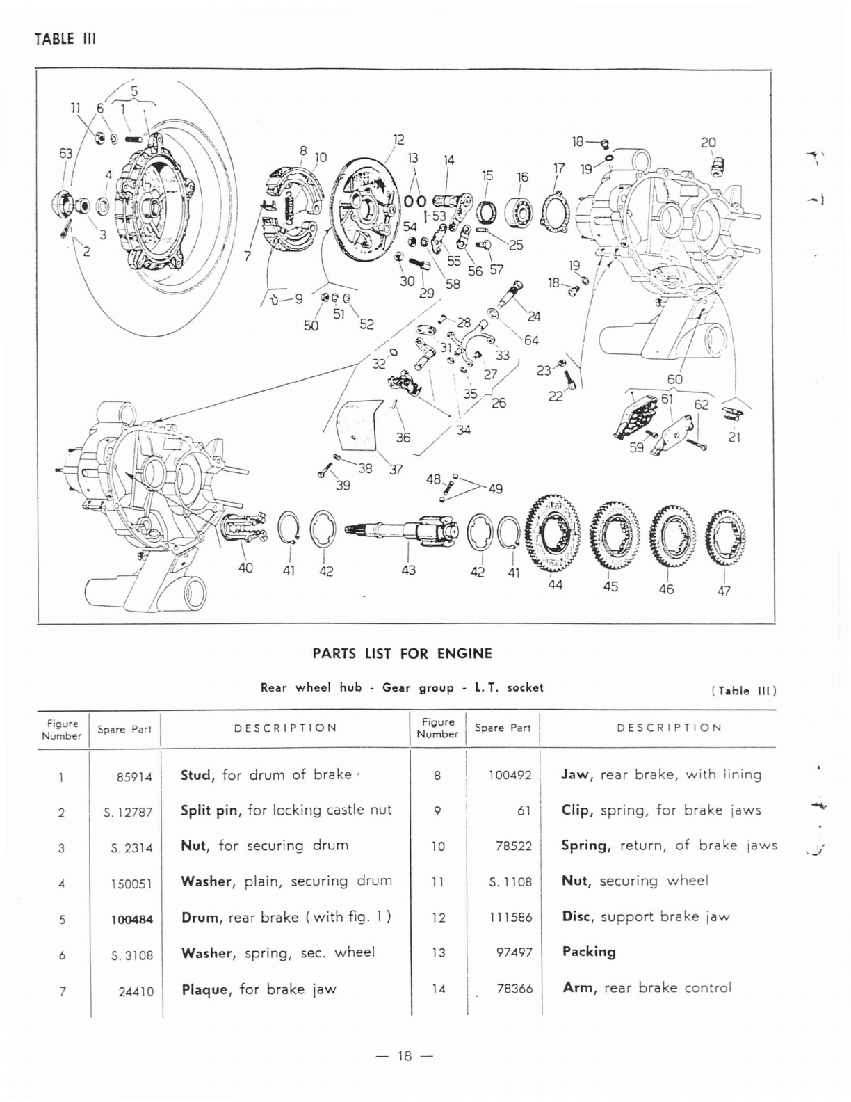
TABLE
III
PARTS
LIST
FOR ENGINE
~,
I
--I
Rear
wheel
hub.
Gear
group·
L.
T.
socket
Figure
II
DESCRIPTION
I
Figure
II
Number
Spare
ParI
Number
Spare
Part
85914 II
100492\
I
Stud,
for
drum
of
brake'
8I
2
5.12787
Split
pin,
for
locking
castle
nut
9
61
3
5.2314
Nut,
for
securing
drum
10
78522
4150051
Washer,
plain,
securing
drum
11
5.1108
5
100484
Drum,
rear
brake
(with
fig.
1)
12
111586
6
5.3108
Washer,
spring,
sec.
wheel
13
97497
724410
Plaque,
for
brake
jaw
14
\.
78366
-
18-
(Table
III)
DESCRIPTION
Jaw,
rear
brake,
with
lining
Clip,
spring,
for
brake
jaws
Spring,
return,
of
brake
jaws
Nut,
securing
wheel
Disc,
support
brake
jaw
Packing
Arm,
rear
brake
control
Figure
Spare
Pan
Number
I
DESCRIPTION
I
Figure
!
Spare
Part
Number
I
DESCRIPTION
15
3/46699
Seal,
spring
-
loaded
of
main-
shaft
41
5.5901
Circlipt
retaining
shoulder
washer
-1
16
17
7563
90899
Ball
bearing
t
clutch
side
Packing
42
42
a)
111996
a)
112008
Washer
t
shoulder,
normal,
of
of
gear
pinions
Washer,
shoulder,
1
st
oversize
18
19
20
2990
Capt
filler, oil
397
Packing
t
for
cap
19301
Breather
42
42
42
a)
112009
Washer
t
shoulder,
2nd
oversize
a)
112010
Washer
t
shoulder,
3rd
oversize
a)
112011
Washer
t
shoulder,
4th
oversize
21
78578
Buffer
43
a)
111596
Mainshaft
22
23
24
25
26
27
90527
Screw,
setting
change
gear
5.1205
Nut
t
setting
change
gear
98787
Bolt
t
securing
stirrup
90306 .
Pivot
pint
for
rear
brake
links
112214
Stirrupt
for
gear
change
(With
parts
Figs.
27
-
28
31 -
33
-
35
-
36).
78945
Slide
t
stirrup,
of
gear
change
44
45
46
47
48
49
50
112378
Gear,
low
speed
112379
Gear
t
2nd
speed
112381
Gear
t
3rd
speed
112380
Gear
t
4th
speed
150110 i
Spring
t
for
balls
5.6379
Ball
5.1108
Nut
t
securing
brake
jaw
sup-
port
disc
23823,
Screw
t
setti
ng
rea
r
bra
ke
5.
1207
Nut
t
setti
ng
rea
r
bra
ke
5.5771 Rivett
for
stirrupt
of
gear
change
S.
3108
Washer
t
spring
link,
brake
link
t
brake
Washer
t
spring
Screw
t
for
L.
T.
socket
l.
T.
socket
g.
a.
(With
parts
Figs.
59
-61 -
62)
.
Bolt
t
for
securing
cable
to
brake
links
70744
85673
42047
94779
5.3109
5. 14402
5.3058
Washer
plain
5.12761
Split
pint
for
arm
axle
5.1426
Nut,
for
securing
bolt
brake
links
53
58
59
52
57
55
54
56
51
60
Cover,
of
the
act.
lever
Union
piece,
for
levers
Packing
Washer
t
spring,
for
cover
Stirrupt
of
gear
change
Washer
t
spring,
for
stirrup
Circlip,
for
stirrup
Pin
78920
78597
78526
110716
5.3105
5.5962
5.6706
5.13010
36
38
30
35
29
32
37
28
34
31
33
~
\
39
40
99462
111589
Screw
t
securing
cover
Selector,
gear
61
62
78598
5.8230
Covert
for
L.
T.
socket
Screw
t
for
L.
T.
socket
a)
The total axial
play
of
the
assembly
of
the
4
gear
pinions
in
respect
to
their
seat
must
be
contained
between
.002"
and
.012".
Should
this
play
exceed
said
tolerances,
the
normal
shoulder
washer
must
be
replaced
by
another
with
proper
oversize.
-
19-
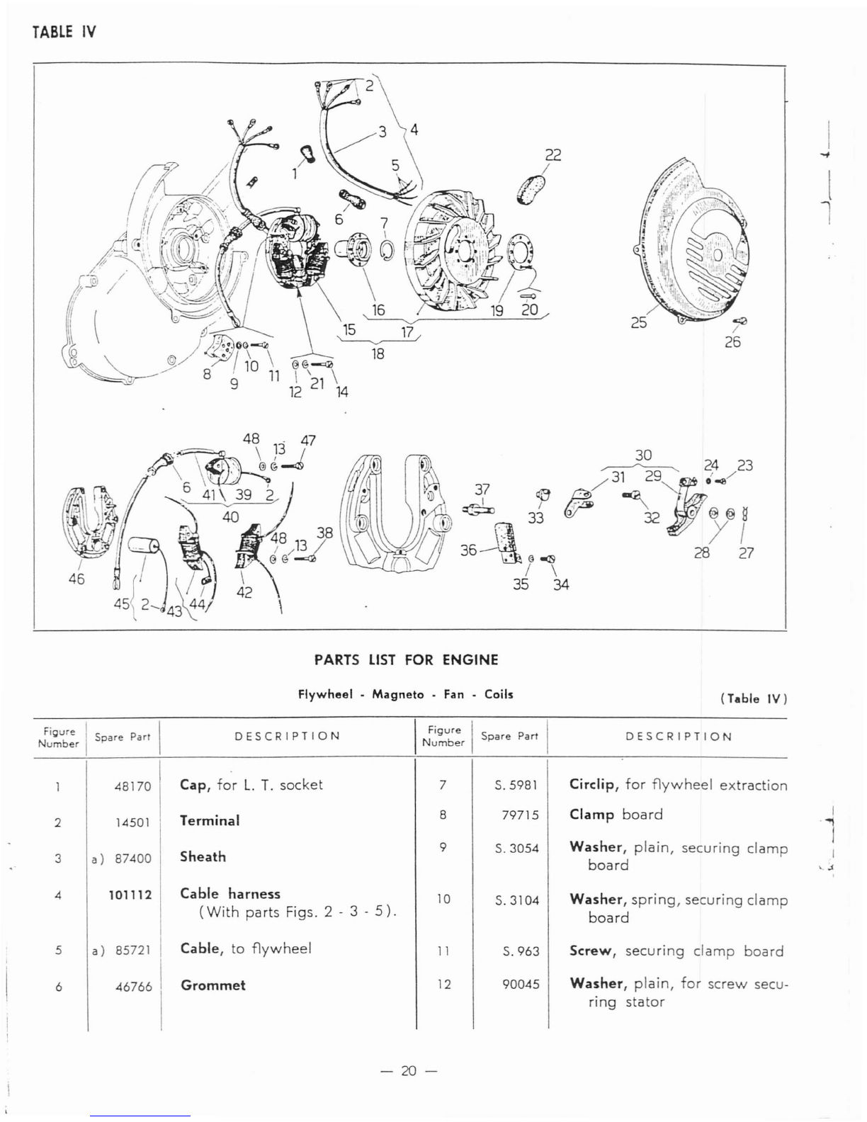
TABLE
IV
I
-#
l
~
2423
37
lIB'
/31
29j'
-a./
~
/
~
~
,-
~
33 W32
.o@@g
36Jl.-S
/
~7
/\
35
34
PARTS
LIST
FOR
ENGINE
Flywheel
.Magneto .
Fan
-Coils
(Table
IV)
FiQure IPI
Number
Spare
art
DESCRIPTION
I
Figure
I
Spare
Part
I
Number
DESCRIPTION
2
3
4
5
6
48170
14501
a)
87400
101112
a)
85721
467661
Cap,
for
L.
T.
socket
Terminal
Sheath
Cable harness
(With
parts
Figs. 2 - 3 -
5).
Cable,
to
flywheel
Grommet
7
8
9
10
11
12
5.5981
79715
5. 3054
5.3104
5.963
90045
Circlip,
for
flywheel
extraction
Clamp
board
Washer,
plain,
securing
clamp
board
Washer,
spring,
securing
clamp
board
Screw,
securing
clamp
board
Washer,
plain,
for
screw
secu-
ring
stator
\.
.1
-20-
Other manuals for 788.94370
1
Table of contents
Other Allstate Scooter manuals


