Currie tech 350 Series User manual

Owners and Riders Instruction Manual (Standard Throttle Version)
350 Series
Electric Scooters
UPDATED 04 07 05

ON THE INSIDE
•Instructions on how to set up your 350 series scooter and charge the battery.
•Tips on how to maintain your scooter and keep it running smoothly.
•Advice on safe riding techniques and safety equipment.
•Answers to frequently asked questions.
•Important words for parents of young riders;
plus warnings and cautions for everybody!
POP QUIZ FOR ALL RIDERS:
WHAT IS RIDING RULE #1?
•Simple. Always wear your helmet when you ride!
CONTENTS:
•Basic Assembly and Tool List . . . . . . . . . . . . . . . . . . . . . . . . . . . . . . . . . . . . . .Page 4
•Set Up and Operation of the 350 series Electric Scooter . . . . . . . . . . . . . . . . .Page 5
• Care and Maintenance: Repairs and Adjustments you can perform . . . . . . .Page 11
•Safe riding tips...for keeping you and your scooter in one piece! . . . . . . . . .Page 16
• Frequently Asked Questions . . . . . . . . . . . . . . . . . . . . . . . . . . . . . . . . . . . . . .Page 17
• Warranty . . . . . . . . . . . . . . . . . . . . . . . . . . . . . . . . . . . . . . . . . . . . . . . . . . . . . .Page 18
Reading this Manual
While you are putting the initial charge into the scooter batteries, PLEASE take time to
read and understand this manual thoroughly. Warning: Failure to follow all instructions
and warnings contained in this manual may result in serious personal injury or damage
to your scooter.
Important Notice to Parents
This is the first of several notes in this manual addressed to parents of young riders:
Check your insurance! Your insurance policies may not provide coverage for accidents
involving the use of this scooter. We recommend you contact your insurance company
or agent to determine if your policies provide for needed accident coverage. We also
recommend you contact your local police or Department of Motor Vehicles to find out
about any special laws or rules governing the use of electric scooters in your locality.
PAGE 2

Warning Notices:
Like most instruction manuals, this one contains a lot of Warnings and Cautions.
Many of them are safety related, and some are connected to legal issues. Please take
time to read through all of them; they are here to help make scooter riding as safe
and enjoyable as possible—especially for kids. Here’s the first:
This Electro Drive scooters is designed to operate on 24 volts only. Use of any battery other
than the 24 volt model supplied with the scooter, or the Currie battery charger provided,
may result in system failure. Curry Technologies Inc. considers such modifications and/or
changes to its products to be a material alteration, thereby voiding any warranties and/or
guarantees in their entirety. CTI will not be responsible for any and/or all injuries or
death or any other damage(s) caused by any such modification.
Notice: If you have any questions about scooter operation, warranty service, or the
equipment and components provided with the 350 series electric scooter, please visit
our website: www.currietech.com, or contact: Currie Technologies Inc., 20600 Nordhoff
St., Chatsworth, CA. 91311. Telephone: 1-800-377-4532, Fax: 1-818-734-8199. Or email
350 series Electro Drive Scooter
PAGE 3

I. BASIC ASSEMBLY & SET UP
IM P O R TA NT:Before turning on and riding your scooter, please read and follow the
set-up and operating instructions first. If you purchased your scooter from a local
re t a i l e r, it should be fully assembled and ready to ride. BUT...if you bought your scooter
and took it home in the carton, then you MUST follow the set-up instructions below
covering assembly and final adjustment. Following these instructions will help insure
safe riding and maximize scooter life.
Tools Required: Here is a list of tools to have on hand for assembling and adjusting
the 350 series scooter:
•Philips head screwdriver
•10mm open end wrench (or small adjustable wrench)
•15mm box wrench (to tighten axle nuts)
•5mm and 6mm allen key (enclosed), 4mm allen key (not included)
•Bicycle tire pump with a schrader valve fitting & pressure gauge
•17mm “Cone-wrench” or thin wrench
Steps for Assembly:
1. Remove scooter from carton and stand it up by lowering the kickstand. Located at
the left side of the rear wheel.
2. Raise the handlebar and lock it securely in place.
3. If your scooter came with a seat and seat post assembly, or if you bought an
optional seat kit, see Seat Kit Assembly Instructions on page 12.
4. Unpack the battery charger from its box. Make sure the power switch on the scooter
is in the OFF position and proceed to charge the scooter batteries. (see Battery
Charging instructions on page 7) While you’re waiting for the batteries to charge,
take time to read through this manual! This could take up to 5 hours.
5. The brake cable comes pre-assembled from the factory. However, you need to
check it carefully to make sure it is properly connected and operating. Test the
brake lever by squeezing it; it should stop the rear wheel easily and NOT come in
contact with the handlebar. If the brake lever needs adjusting, follow the detailed
instructions for brake adjustments on page 9.
6. Before riding, test the throttle grip with the power switch off (also pre-assembled
from the factory) by twisting it towards you while standing in the normal rider
po s i t i o n . It should turn easily and immediately spring back to the “power off”
position when you release it.
PAGE 4

If the throttle does not operate as described, DO NOT RIDE THE SCOOTER. Call the
CTI Customer Service line at: 800-377-4532 for further instruction.
7. Tire Pressure: The correct tire pressure for the 350 series tires
(size: 12 1/2” X 2 1/4”) is 35 psi. Check it with a reliable tire pressure gauge and
inflate as needed. Caution: Do not use an unregulated compressor when inflating
your tires. Gas station compressors typically deliver too much volume for bicycle type
tires, and may cause them to burst.
Caution: Three Items for Riders to Double Check:
1. Before every ride, check the Handlebar Quick Release Lever to make sure it is
locked tight in the “Closed” position. (see instructions on page 5 and 6)
2. Also check your tire pressure regularly. Do not ride on under inflated tires. All bicycle
type tires lose small amounts of air naturally.
3. Test your brake operation before every ride to insure safe and reliable
stopping performance.
II. ASSEMBLY, ADJUSTMENT AND OPERATION OF ALL COMPONENTS
1. Handlebar Assembly and Adjustment
Caution: The 350 series scooter is equipped with an “Easy Fold” handlebar and stem
assem bly. Take care not to pinch your hand or any of your fingers in the hinge when you are
raising and locking the handlebar in place. Also be careful to avoid pinching or crimping the
brake and throttle cables in the hinge whenever you raise or lower the handlebar.
a. To raise and lock the handlebar
properly, first lift the handlebar to
its upright position while Tak i n g
hold of the Quick Release (QR)
lever and pulling back the center
pin (see figure a) so that the top
part of the handlebar hinge makes
full contact with the bottom part.
Then let the center pin slide back
into its locked position.
b. With the QR lever in its “open”
position (see figure b), lift the QR
bolt up and into the slot in the
upper hinge plate. Then flip the QR
lever down into its fully locked
and closed position. The cam
PAGE 5
figure a

action of the QR lever
should lock the handle-
bar hinge down firmly.
Important Notes: If the
quick release lever is
either too tight and
cannot be flipped to its
locked position, or it is
too loose and too easily
can be flipped to its
locked position, place
the lever in its open
position (fig. D) and
adjust the 10mm nut
underneath the center
pin. Adjust only 1/2 turn
at a time and test it again
for proper tension when
flipped closed. The lever
should be very tight in
its closed position (fig. e)
and unable to
vibrate loose.
c. To unlock and lower
the handlebar, reverse
steps a. through c.
above.
If you are unable to lock the handlebar folding hinge properly, DO NOT RIDE THE
SC O OTE R . Contact CTI Customer Service at 1-800-377-4532 for further instructions.
DO NOT RIDE YOUR SCOOTER unless the handlebar assembly is properly closed
and locked properly. Failure to do so may result in serious injury or death to the rider
or severe damage to the scooter.
2. Stem Assembly and Adjustment
The stem of the 350 series electric scooter comes fully installed and tightened from
the factory. The stem itself is attached to the lower hinge plate and includes a bicycle
style stem expander bolt and expander wedge. The stem fits into the steerer tube of
the fork (inside the head tube of the scooter), and it is tightened in position with the
expander bolt and wedge. Should the stem ever come loose, you can adjust it by a)
opening the handlebar hinge, b) loosening the expander bolt and wedge with a 6mm
allen key (included), c) repositioning the stem in the steerer tube and then
d) re-tightening the expander bolt and wedge.
PAGE 6
figure b figure c
figure d figure e

3. Battery Pack, Charger Port and Charger
The 350 series electric scooter comes with a 24 Volt/10 AH “Plug and Play” battery pack.
The battery pack is installed at the factory, and it is located under the deck plate. To
access the battery, if necessary, turn the power switch to the OFF position (fig. a),
unscrew the “D” ring bolt located beneath the power switch at the front center of the
main deck and remove the deck.
Electro Drive Charger
The 350 series scooter comes with its own
“Electro Drive Smart Charger” that connects
with an easy-access charger port for recharging
the batteries. This charger unit has a light
which shows battery charge status. Refer to the
instructions that appear on the charger unit.
How to Charge the Batteries
1. Important: Make sure the power switch on
the scooter is turned to the OFF position.
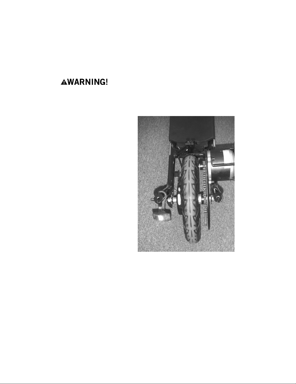
2. Insert the Battery Charger’s Round Connector
into the Charger Port (fig. b) located below the
power switch on the scooter and then plug the
charger electric cord into a standard, grounded
110V AC outlet.
3. Let the batteries charge until the charger
light turns solid green, then unplug the
charger from the scooter and the AC outlet.
Ca ut i o n : Batteries “like” to have a full charge,
so be sure to recharge them fully after each
ride. If you leave them in a run-down condition
and do not quickly recharge them, it will shorten
their life expectancy. Charger may get warm to
the touch, so make sure you charge them in
an open area and do not lay anything on the
charger unit itself. Although you cannot
over-charge the batteries using the Currie
“Smart Charger”, we recommend you do not
leave the charger plugged in for more than
24 hours maximum.
Use only the Currie Electro Drive Smart
Charger to charge the 350 series batteries.
Using any other charger may damage the
PAGE 7
figure a
figure b

batteries and void your warranty.
Changing the Battery Pack
1. Make sure the power switch is set
to the OFF position.
2. Undo the deck plate mounting bolt
and remove the deck.
3. Disconnect the battery power pack
connector (cut zip tie holding the
wire connector if necessary) and lift
the battery pack out of the scooter’s
battery box.
4. Place the new or fully charged battery
pack into the battery box.
5. Reconnect the power pack connector
cable and tuck all of the cables into
the box.
6. Be sure that no wires or plugs are
exposed through the bottom of the
battery tray or frame.
7. Replace the deck plate and re-attach
the “D” ring mounting bolt. Make
sure all corners fit and the bolt is
PAGE 8
figure 3
figure 5
Throttle Operation
Your scooter’s motor speed is controlled by an on-demand, variable speed, Twist Grip
style throttle. That means the further you twist the throttle towards the rider, the faster the
motor will propel you until reach the scooter’s top speed of about 15 mph. The throttle is
located on the handlebar just to the left/inside of the right hand handlebar grip.
• To accelerate or go faster - twist the throttle backwards or towards the rider.
• Twisting the throttle all the way backwards, until it stops rotating freely, will give
you full power. (This also uses the most battery power of any throttle position.)
• To go slower - partially twist the throttle backwards until you find your safe and
comfortable speed.
• To decelerate or slow down - completely release the throttle.
• Remember: Always fully release the throttle lever when you apply the brake.
• When you release the throttle, it will spring back / return to the off position.
Handlebar Grip Throttle
Twist Backwards
to Accelerate
Throttle Body Handlebar
Throttle Wire
Brake Wire
Brake Lever

secure. The scooter is ready to ride!
If you do not fully understand how to operate your scooter throttle properly, DO NOT
RIDE YOUR SCOOTER. Contact CTI Customer Service for information and instructions
at 1-800-377-4532.
Brake Operation
The 350 series electric scooter is
equipped with a large diameter rear band
brake. It is operated using the left hand
brake lever on the handlebars and is
designed to provide excellent stopping
power for your scooter. Squeeze the
brake lever firmly (fig. 1) to bring your
scooter to a safe, controlled stop.
Caution! The brake lever itself should never
touch the handlebar or grip when squeezed
fi r mly. If it does, then immediately STOP
RIDING and adjust the brake cable.
All brakes need periodic adjustment. However, the band brake mechanism itself
should be adjusted only by a qualified service technician. If or when it needs service,
take your scooter to your local bicycle dealer or to a retailer who offers service for this
universal band brake system. Improper adjustment of your brake can cause poor
braking and lead to an accident, serious
rider injury or death.
Brake Cable Adjustment
If your break wire stretches (as most new wires
do during the initial “breaking-in” period), your
brake lever will require a longer “pull” to
engage the brake and may even touch the
handlebar when squeezed. Use the
adjusting barrel on the brake lever. Loosen the adjusting barrel lock nut (fig. 2), back
the adjusting barrel out of the lever a turn or two, then re-tighten the lock nut to
secure the barrel.
2 Cautions:
1) Do not allow the adjusting barrel to extend more than 5 full rotations out of the
brake lever.
2)Always test your brakes after making any adjustment to be sure they are operating
properly before riding.
PAGE 9
figure 1
figure 2

Cau ti o n : If you reach the limit of the cable adjustments described above and you are
still experiencing poor braking performance, do not continue to ride. Do not attempt to
adjust the cable any further or attempt to adjust the band brake. Take your scooter to a
qualified mechanic for proper service, or call CTI Customer Service at: 1-800-377-4532.
Proper brake performance and adjustment is vital to safe scooter operation. Never
ride your scooter unless your brakes are adjusted and working correctly. The same
goes for chain and drive train adjustments. Do not ride you scooter if any part of the
drive train is not in good working
order. For answers to any questions
about the adjustments described
above, please call CTI Customer
Service at: 1-800-377-4532.
5. Drive Train Assembly
The 350 series electric scooter is
equipped with the patented Currie
Technologies Electro Drive propulsion
system, the finest available in today’s
rapidly growing Personal Electric
Transportation market. The Currie
Electro Drive features a DC motor
with direct chain drive to the rear
wheel, a weather and dust resistant
Con t r o l ler, built-in freewheeling (a
feature that allows the scooter to
coast when the power is not
engaged), plus rechargeable and
recyclable lead acid batteries that
provide many hours of trouble free
riding. The 350 series motor and
drive train come fully assembled and
“ready-to-ride” from the factory.
IMPORTANT: All Electro Drive Motors, Throttles and the Controller are factory sealed
units and are not user serviceable. Do not open or tamper with any of the factory
sealed units; doing so may result in electric shock or injury and will render them
inoperable. For answers to service
questions regarding the 350 series drive train, please contact your local dealer, or call
PAGE 10
The Currie Drive Train Assembly

CTI Customer Service at: 1-800-377-4532.
6. Chain Tension Adjustment
Like a new brake wire, the direct drive chain can stretch during use or may occasionally
come out of adjustment. Regular attention to proper chain tension and lubrication
will minimize the risk of the drive chain falling off the rear sprocket and help your
scooter maintain optimum performance. Properly adjusted, the drive chain should
have 5 to 6mm of up-and-down travel or slack. Note: Currie Technologies strongly
recommends that any chain tension adjustment be performed by a trained scooter or
bicycle mechanic. The Direct Chain
Drive System allows for adjustment of
chain
tension in the following steps:
• Loosen (do not remove) the right side
axle nut (15mm) and the motor plate
fixing bolt (5mm Allen)
• Loosen the right side 17mm “inner
axle nut”
• Slide the motor plate with motor
forward to tighten the chain, or towards
the rear to loosen the chain. (Note: a
slight movement will dramatically effect
the chain tension, so try a little at a
time until it is correct!)
• When proper chain tension is
achieved (5-6mm slack), tighten the
17mm inner axle nut first, then the
15mm axle nut, and the 5mm motor
plate fixing bolt.
Note on Chain Lubrication: To help
maintain both the performance and life
of your drive chain, lubricate it about
PAGE 11
figure a
figure b
figure c

once a month using any quality bicycle chain
lube. Take time when you do so to check the
chain tension.
7. Optional Seat and Seat
Post Assembly
The seat assembly is included. The seat
assembly can be easily attached to the scooter.
The assembly consists of: a) Comfort Seat, b)
Seat Post, c) Seat Tube, d) Quick Release Seat
Post Clamp (QR) e) a separate sheet of
assembly instructions and f) Basket. The Seat
Tube is designed to slide into the Seat Tub e
Receiver located in the frame. Here are the steps
to follow in order to mount the Seat and Seat
Post assembly:
1. Slip the seat clamp in the seat over the
small end of the seat post and tighten the
clamp nuts with a
14mm wrench. (Do not fully tighten the
clamp until you have adjusted the seat
position to your liking. See point 5 below.)
2. Attach the seat post QR to the seat tube;
then insert the seat post into the seat tube.
To secure the post in the seat tube,
push the QR lever to its “Closed” position.
3. Attach basket to the bracket on the rear of the seat tube with a 5 mm Allen wrench.
4. Align the seat tube assembly with the water bottle holder fixing bolts pointing
towards the front of the scooter.
5. Insert the seat post tube completely into the seat tube receiver in the frame. Make
sure the indexing pin is correctly aligned in the slot during this step.
6. Use a 5mm allen key to tighten the seat tube fixing bolt on the the seat tube receiver
in the frame. Caution: Take care not to over-tighten the bolt, but it should be
tightened enough to hold the seat post tube securely in the receiver. (fig. b)
7. Two Adjustments: 1) You can adjust seat height by opening the QR clamp, moving
the seat post up or down as desired, and then re-tightening the QR clamp. 2) You
can adjust the angle and alignment of the seat to a comfortable position by loosening
the seat clamp nuts using a 14mm wrench, adjusting the saddle tilt position, and
then re-tightening the clamp nuts. Caution: Be sure to tighten the seat clamp nuts
sufficiently to prevent the seat from twisting or tilting when in use.
Never extend the seat post beyond the minimum insertion mark located on the post.
Make sure the indexing pin on the seat post tube is aligned in the receiver slot and the
PAGE 12
figure a

tube fully inserted. Before you ride the scooter, make sure
you have tightened all parts of the seat assembly properly,
especially the QR lever. Riding with a loose seat or seat
post may cause a rider to fall, possibly damaging the
scooter and causing serious injury.
8. Wheel Removal & Flat Tire Repair
Front Wheel Removal:
Using a 15mm box or adjustable wrench, loosen both
axle nuts enough to unhook the safety washers from
the fork. Then by lifting the front end of the scooter,
pull the wheel down and out of the front fork. Caution:
Make sure the scooter does not fall over and cause
damage to itself ….or you(!).
Rear Wheel & Drive Assembly Removal:
Mechanic’s Tip: Put wood blocks under the scooter to lift
the back end and rear wheel off the ground or your work
bench surface. This will make it easier for you to handle the
rear wheel assembly and access the chain.
a. Remove the main deck with the D-ring bolt.
b. Locate and detach the motor wire from the controller at
the white clip.
c. Remove the motor with the small sprocket from the
motor plate with the 3 (5mm) bolts.
d. Loosen and remove both axle nuts (15mm)
e. Loosen and remove the motor plate fixing bolt (5mm
Allen) on the lower right side of the frame.
f. Disconnect the brake wire from the band brake actuator
arm by removing the nut (10mm) and washer from the
cable pinch bolt. Mechanic’s Tip: The brake wire has a
lead end protector, which can keep the pinch bolt and
spring from coming completely off the wire. Don’t
remove it.
g. Loosen and remove the band brake fixing bolt using a
4mm Allen wrench and an 8mm wrench. This bolt also
holds the rear cable hanger in place. (Be sure to keep the
pinch bolt, washer, nut spring and cable hanger together.)
h. The rear wheel with sprocket, band brake assembly, and
motor plate can now be removed from the rear dropouts
of the frame.
Front Flat Tire Repair
• Remove both axle nuts and safety washers with a
15mm wrench. The front wheel should be albe to be
PAGE 13

easily removed from the front forks.
• With a plastic bicycle tire lever “un-zip” one side of
the tire from the rim.
• Remove the inner tube from the tire.
• Inflate the tube and inspect for leaks or punctures.
• Patch the tube as needed. If the tube is too badly
damaged to repair, replace it with a new one
(12 1/2” x 2 1/4”).
• Be sure to inspect the inside of the tire for any
sharp edges, thorns or glass that could have caused
the puncture to the inner tube. If the tire has any
cuts it will need to be replaced too.
To reassemble the front wheel with its tire and tube:
• Slightly inflate the new (or patched) inner tube to
make it take shape.
• Insert the valve thru the hole in the rim.
• Feed the tube into the tire
• Push (by hand only) the tire and tube all the way
over the rim so that the previously “un-zipped” side
of the tire is next to the rim.
• With a plastic bicycle tire lever “zip” the tire side
back in place. (Note: Go slow to make sure not to
damage the tube)
• Inflate tire slowly, checking periodically to make
sure the tire is properly and evenly seated all around
the rim, not pinching the tube or lifted off the rim at
any point.
• When tire is properly seated, inflate to recommended pressure (35psi)
Front Wheel Installation
Raise the front end of the scooter and lower it onto the front wheel axle. Make sure the
axle seats properly in the dropouts. Center the wheel in the forks and tighten both axle
nuts. Spin the wheel to make sure it is centered in the forks and the axle nuts properly
ti ght ene d.
Rear Wheel Installation
Note: The order of this installation is very important.
• Make sure the chain is hanging around the right side of the hub, between the tire
and large sprocket.
• Insert the rear wheel, band brake, large sprocket and motor plate assembly all the
way forward into the fame dropouts, but do not secure nuts tightly at this time.
• Align the band brake to the slotted tab on the lower left of the frame and secure in
place with its bolt (4mm Allen and 8mm wrench), the brake cable hanger, and the nut.
• Attach kickstand and secure left side axle nut tightly.
PAGE 14

• Align the motor plate threaded hole to the frame tab and thread and secure the
motor plate fixing bolt (5mm Allen) in place.
• If the motor plate is no longer aligned with the right side frame tab, loosen the
17mm inner axle nut to allow you to re-locate the threaded hole to the frame tab. You
will then need to re-adjust the chain tension. See page 11, section 6 for instructions.
• Thread the top motor bolt (5mm Allen) in place, but do not tighten completely yet.
• Pivot the motor clockwise or bottom towards the rear of the scooter enough to put
the chain around both the large and small sprockets.
• Once chain is in place pivot the motor counter clock-
wise or bottom towards the front of the scooter and
secure all three motor bolts tightly.
• Tighten right side axle nut with safety washer.
Attach the Brake Cab l e : First make sure the brake wire is
inserted through the adjusting barrel on the rear cable
hanger. Then slide the spring over the brake wire.
Thread the brake wire through the hole in the cable pinch bolt. Next insert the pinch
bolt (with wire) through the brake actuator arm, starting from the back side of the arm
so that the nut can be tightened from the outside. Place the washer over the pinch bolt
and install the nut. Hand tighten the nut only at this point.
Adjust the Brake Cable: To adjust the brake wire correctly, pull and hold it taut with
pliers through the pinch bolt, push the brake actuator arm forward along the wire and
then tighten the cable pinch bolt using a 10mm wrench. Immediately test the brake
cable adjustment by squeezing the brake lever. When the brake is fully applied it
should not touch the handlebar, and the wheel should spin freely when you release
the brake lever. It may take you 2 or 3 attempts to make this adjustment.
Install the Kickstand: Attach the kickstand to the left dropout using the 2 phillips
headed bolts and tighten in place.
III. Riding Instructions and Safety Tips
Riding instructions
Your 350 series Electro Drive scooter is as easy to operate as “1-2-3.” (Got your helmet
on? Make it a habit!)
Who can ride?
The 350 series scooter has a rider weight limit of 240 pounds and is intended for riders
age 12 and up. Riders should have experience operating a multispeed bicycle with hand
brakes, and have both good balance and coordination.
Starting up
1. Turn the power switch ON and place one foot on the deck with both hands on
the handlebars.
PAGE 15

2. Push off with your other foot and coast the scooter – just as you would when riding
a non-powered scooter.
3. Slowly twist the throttle grip towards you to apply power to rear wheel.
Stopping
To slow down or come to a stop, twist the throttle grip away from you or release it
completely. Squeeze the brake lever on the left side of the handlebar at the same time
to come to a safe stop. (Note: It is not necessary to skid the wheel in order to slow or
stop the scooter. Save this in case of emergency only!)
Storing your Scooter
When you are done riding, flip the power switch to OFF and plug in the battery charger.
Caution: Do not charge your battery for more than 24 hours at one time.
Safe Riding Tips
These are usually a drag to read, we know. Especially for younger riders. But following
them doesn’t cost anything, and we think they are critical to keeping both rider and
scooter away from dangerous situations. Here’s our list...best if read aloud by a parent!
1. Ride Responsibly: Always wear a helmet when you ride. If you are a new rider, wearing
elbow and knee pads will also help keep your scooter riding safe and enjoyable. Protect
yourself on the road!
2. Ride on Smooth Pavement: Your Electro Drive 350 series scooter was designed to
be ridden only on smooth, dry pavement. Caution: Riding off-road in the dirt or riding
in wet conditions will damage the scooter, so don’t do it. The Limited Warranty will
not cover damages sustained by off-road riding.
3. Ride Straight: Do not stunt ride or jump the scooter! The 350 series scooter is simply
not designed or built for stunt riding or jumping, and if riders abuse and damage the
scooter by riding in that manner, the Limited Warranty won’t cover it.
4. Ride Alert: Whenever you ride, follow all traffic regulations, especially stop signs,
traffic signals, pedestrian crosswalks, etc. If you have to cross a busy street, or many
lanes full of traffic, cross safely by walking your scooter in a designated crosswalk
zone. Note: If you want to know if any special laws govern scooters and their
operation in your locale, contact your local police station or Department of Motor
Vehicles for information.
5. Ride Defensively.When in doubt, always yield the right-of-way to the other guy.
Always assume that other drivers, pedestrians, motorcyclists and cyclists just don’t
see you there. Or won’t...until it’s too late. And because electric scooters are very
quiet on the road, other riders and drivers cannot really hear you coming.
6. Ride Smart. DO NOT ride your scooter at night unless you equip it with a
functioning, CPSC approved bicycle headlight and taillight. 3 Tips for Riding Smart:
1. Find a loud bell or horn, mount it on your handlebars and use it to warn others
that you’re coming. 2. Wear a brightly colored shirt or jacket to increase your visibility
PAGE 16

to other drivers and riders. 3. DO NOT deliberately skid your back tire when stopping.
Skidding leads to a loss of control, and it will quickly damage your tire, shorten its
useful life and cost you money!
7. Ride Safe: Give yourself plenty of room to stop. This scooter travels much faster
than non-powered scooters, and it carries the added weight of a motor and battery
pack. Both the faster speed and the additional weight of the 350 series scooter extend
the safe stopping distance compared to non-powered scooters.
Wet conditions can increase stopping distances by as much as 6 times the normal,
dry pavement stopping distance. And skidding caused by braking on wet pavement is
inherently dangerous and should be strictly avoided.
8. Be Responsible. DO NOT let others ride your scooter until they read the manual
and fully understand how to operate first. You read the manual, right? So they can
too! Another safety rule: No Passengers! This scooter is designed to carry one rider
only (maximum weight limit is 240 lbs.) only!
IV. Frequently Asked Questions (FAQ’s)
•How far with the 350 series scooter go on a full charge?
Up to 8 miles per charge on level ground.
•How many hours will the scooter run on a full charge?
On average, it will run 1/2 hour to 1 hour per charge on level ground.
Note: Riding at full-throttle dramatically reduces your range.
•What is the top speed of the scooter?
Up to 15 mph on level ground. Note: Both the range per charge and the top
speed of the scooter depend on many variables, including riding conditions,
rider weight, battery charge, etc. Scooter performance, of course, will
vary accordingly.
• Can I ride my scooter in wet conditions or on wet pavement?
No! Because riding in water can cause rider to lose control. And because
water might enter the battery compartment and cause the motor controller
or other parts of the electrical system to fail, we strongly recommend you do
not operate the scooter on wet pavement, through puddles, in snow...or
anywhere your scooter is liable to get wet.
•What is the correct air pressure for the tires?
The proper air pressure for the front and rear tires is 35 psi.
•What is the weight limit of my scooter?
One rider up to 240 pounds maximum.
PAGE 17

•How often should I recharge the batteries?
Recharge them after every ride! Your scooter will perform best when the
batteries are fully charged. And to help prolong battery life, make sure they
are fully charged before you store the scooter for any extended period of time.
•How long should it take to charge a fully discharged battery?
About 5 to 6 hours using the power supply provided with the scooter.
•Where can I purchase additional or replacement parts, if needed, such as batteries
or an extra charger unit?
They can be purchased directly from Currie Technologies at 1-800-377-4532.
•Where can I get replacement tires?
The 12 1/2” x 2 1/4” scooter tires may be available at your local bike or scooter
sh o p . However, if you cannot find them locally, you can order them directly
from CTI Customer Service by calling: 1-800-377-4532.
•What is the length of the Limited Warranty?
Frame = 180 days from date of purchase.
Motor and Electro Drive = 180 days from date of purchase.
Batteries = 180 days from date of purchase, prorated 33.3% monthly after the
first 90 days.
Tires = 30 days from the date of purchase*.
PAGE 18
FASTEN RECEIPT HERE.

Important Note: Keep a copy of your purchase receipt on hand and available in case
you should need service under the warranty. We recommend you attach a copy of
your receipt to this manual and store both in a safe and easy-to-remember place!
V. Limited Warranty
Currie Technologies Inc. (CTI) manufactured or distributed “Electro-Drive” powered products are warranted to
the original retail purchaser to be free from defects in materials and workmanship in the frame and components,
except for batteries, tires and inner tubes for a period of 180 days from the date of purchase. Batteries are
warranted to the original purchaser to be free from defects in materials and workmanship for a period of
ninety (90) days from the date of purchase, and are prorated at a declining 33-1/3% per month, or fraction
thereof, for the subsequent three months. Tires and tubes are warranted to be free from manufacturing
and material defects for 30 days(*). This warranty does not include damage from normal road hazards, flat
tires, tire cuts and the like, skid wear or blowouts from over inflation or other such misuse, or normal wear.
Warranties are limited to repair and/or replacement of scooters and/or parts judged by CTI at its sole
discretion to be defective.
CTI Limited Warranties do not cover or apply to the following: Normal wear and tear; any damage, failure
and/or loss caused by accident, shipping, misuse, neglect, abuse and/or failure to follow instructions or
warnings as stated in the applicable owner’s manual or other printed materials provided with the product;
damage, failure and/or loss caused by the use of the product for stunt riding, ramp jumping, competition,
off-road use, acrobatics, trick riding or other similar activities, or use in any other manner for which such
products were not specifically designed. This warranty does not apply to any products or components,
mechanical and/or electrical, which have in any way been altered from their original configuration by any
person. CTI will not be liable and/or responsible for any damage, failure or loss caused by any unautho-
rized service or use of unauthorized parts.
The CTI Limited Warranty does not cover or apply to any Currie product used for rental or commercial purposes
unless the specific product is designated, labeled or marketed by CTI as acceptable for rental or commercial use.
All warranty claims must be made directly to the selling retailer. The selling retailer is the primary provider
of warranty support and customer service. CTI may choose to perform warranty service at the sole choice
of CTI. The original owner of the product must provide proof of purchase prior to approval of any warranty
claim. Under no circumstances does this limited warranty include any costs associated with shipment
and/or transportation to or from the retailer or CTI. CTI, at its sole discretion, has the option of replacing
with a new part, or factory re-certified part, or repairing any defective product and/or component thereof,
or to pay the owner of such a product an amount equal to the original purchase price of such product. The
original owner shall pay for all costs of labor associated with any warranty claims.
This warranty supercedes all previous warranties. The warranties stated herein are in lieu of and expressly
exclude all other warranties not expressly set forth herein, whether expressed or implied by law or otherwise,
including, but not limited to, any warranties for merchantability and/or fitness for any particular purpose.
CTI shall in no event be liable or responsible for incidental or consequential losses, damages or expenses
in connection with their scooter products. The liability of CTI hereunder is expressly limited to the replacement
PAGE 19

of goods complying with this warranty or at the sold election of CTI to the repayment of an amount equivalent to
the purchase price of the product in question. CAUTION: Some states may not permit the exclusion or
limitation of consequential damages and, therefore, such limitations may not apply to the consumer in
which some impermissible exclusions are involved.
Contact:
Currie Technologies Inc.
20600 Nordhoff St.
Chatsworth, CA 91311
phone: 800 377 4532
www.currietech.com
Pre-Ride Checklist
We recommend you perform each of the checks on this list before each ride.
•Check the tires for any cuts or unusual wear.
•Check the folding handlebar hinge and make sure it is properly closed and locked.
Make sure the handlebar turns freely and is not obstructed.
•Check all cables and wires to make sure they are not frayed or broken.
•Check the brake lever and make sure it is mounted tightly on the handlebar.
•Pull the brake lever to make sure that it does not bottom out on the handlebar and
the brake holds the scooter from being pushed forward.
•If your scooter is equipped with a seat assembly, check to make sure it is properly
installed and tightened.
•Check all 4 axle nuts to make sure they are tight.
• Finally...check you helmet! Is it properly buckled on? Good!
Ride Safe! Obey all local traffic laws and always ride with your helmet on! It’s the cool
thing to do. Just watch the pros who ride... any 2 wheel vehicle!
PAGE 1
350 series
Electric Scooters
The 350 series electric scooter is manufactured and distributed exclusively by Currie
Technologies™, 20600 Nordhoff St., Chatsworth, CA 91311. Made in China.
Table of contents
Other Currie tech Scooter manuals

Currie tech
Currie tech e4.5 eZip User manual

Currie tech
Currie tech EZ 3 NANO User manual

Currie tech
Currie tech Ezip User manual

Currie tech
Currie tech 500 DD Series User manual

Currie tech
Currie tech e4.5 eZip User manual

Currie tech
Currie tech 300 Series User manual

Currie tech
Currie tech 600 Series User manual

Currie tech
Currie tech 500 DD Series User manual