Allstate 788.102 Use and care manual

OPERATING INSTRUCTIONS
AND
PARTS LIST FOR
MOTOR SCOOTER
,--------
MODEL NUMBERS
788.102 788.103
788.104
One
of
the
above
numbers
is
the
Model
Number
of
the
Allstate
Motor
Scooter.
It will
be
found
on
a
plate
attached
to
the
outside
of
the
hinged
door
directly
under
the
seat.
Always
mention
the
Model
Number
in
all
correspondence
regarding
the
Scooter
or
when
ordering
repair
parts.
,-----
HOW
TO
ORDER REPAIR PARTS
All
parts
listed
herein
may
be
ordered
through
any
Sears
retail
or
mail
order
store.
In
ordering
parts
bymail
from
the
mail
order
store
which
serves
the
territOly
in
which
you
live,
Selling
Plices
will
be
furnished
on
request
or
parts
will
be
shipped
at
prevailing
prices
and
you
will
be
billed
accordingly.
WHEN ORDERING REPAIR PARTS,
THE FOLLOWING INFORMATION: ALWAYS
GIVE
1.
The
Part
Number
in
this List.
2.
The
Part
Name
in
this List.
3.
The
Model
Number
of
the
item.
being
able
We
sug-
papers.
your
times.
valuable
It will
assure
service
at
all
with
other
is
valuable.
proper
parts
keep
it
This
list
to
obtain
gest
you
SEARS, ROEBUCK
AND
CO.
Scooterworks
USA Inc.
5709 N.
Ravenswood
Chicago,
IL
60660
ph: 773.271.4242
fx:
773.271.5012

Fig.
1 - ALLSTATE
Scooter
WARNING
In
order
to
keep
your
ALLSTATE
Scooter
in
per-
fect
running
condition
and
not
to
void
the
guarantee,
always
have
your
machine
repaired
at
a
Sears,
Roe-
buck
and
Co. Store.
Special
care
should
be
taken
in
regard
to
the
fuel
mixture
which
should
be
regular
gasoline
and
oil
of
the
make,
grade
and
in
the
amount
prescribed
in this booklet.
Ethyl
gasoline
should
never
be
used.
Do
not
use
Allstate
compounded
motor
oil
or
other
premiumsheavy
duty
mo
or
oils
with
de
er-
gents.
The
inexperienced
operator
should
exercise
caution
in
applying
front
wheel
brake,
to
avoid
locking.
In
order
to
allow
a
gradual
running-in
of
all
parts,
particularly
those
of
the
engine,
customers
must
not
use
full throttle
opening
for
the
first 600 miles.
- 2 -

THROTTLE
CONTROL
GRIP
CHOKE
KICKS
TARTER
FUEL
COCK
TTOR
SWITCH,
HORN
BUTTON
EARTH
CONTACT
GEAR
SHIFT-CLUTCH
CONTROL
HORN
R
AR
BRAKE
PEDAL
FRONT
BRAKE
LEVER
Fig.
2 -
Controls
of
Allstate
Scooter
MAIN
SPECIFICATIONS
Fuel
tank. -
Total
capacity:
1.3
gals;
Reserve:
0.17
gals.;
Three-way
cock:
«
open»
-«
closed»
-«
reserve»
Wheels.
-Of
pressed
steel
sheet,
interchangeable
and
easily
removable,
since
they
are
assembled
in
an
automobile-like
system.
Tires:
dia.
3.50 X8in.
Brakes. -
Expanding
type.
Front
brake:
control
lever
on
right
hand
side
of
handlebars
Rear
brake:
control
pedal
on
right
hand
side
of
floorboard.
Frame. -Of
pressed
and
spot-welded
steel
sheet,
with
strem-lined
monocoque-type
structure.
Suspension. -Front
wheel:
coil
springs;
rear
wheel:
coil
spring
and
hydraulic
shock
absorber.
Engine. -Two-stroke, flat
cast
iron
cylinder
and
cast
aluminum
alloy
cylinder
head.
Bore .124.850 cc. (7.63 cu. in.)
Stroke
56.5 mm. (2.22 in.)
Displacement
49.8
mm
..
(1.97 in.)
Effective
power
at
4500
rpm
4.5 HP
Compression
ratio
6.4 : I
Transmission. -Directly from
engine
to
rear
wheel
through
clutch,
cushion
drive
and
gear
box.
Starting. -
By
means
of kickstarter,
right
hand
side
of scooter.
Gear
box. -
3-speed
drive
with
mesh
gears
in
oil
bath.
Its control is
coupled
with
that
of
the
clutch,
on
left
hand
side
of
handlebars.
Clutch. -
Wet
type,
steel
plates
with
cork
inserts.
Two-cable
control.
Ignition. -
By
flywheel
magneto.
Lighting. -
By
flywheel
magneto,
feeding
both
head
lamp
(two-beam)
and
tail
lamp.
Fuel
consumption:
(Gasoline
-oil
mixture)
Max.
speed
Wheel
base.
Max.
width
on
handlebars
Max.
length
of the
scooter
Max.
height
Hgt. of
saddle
above
ground
Ground
clearance
Turning circle .
Weight
IG6-118
miles
per
gal.
43.7
m.p.h.
45.6 in.
31
in.
66 in.
40 in.
31
in.
8.6 in.
59 in.
185 Ibs.
- 3 -

Fig.
3.
-
Steering
lock
Steering
Lock. - A
suitable
security
kck
is
ar-
ranged
on
the
harne,
near
the
handlebars.
Turning
the key
anti
clockwise
and
the
handlebars
to
the
left,
the lock
engages
the
lugs
welded
on
the
st(1.;ring
column,
so
that
the
machine
can
only
turn
around.
Turn the
key
clockwise
and
the
handlebars
back
to
normal
position
for
releasing
the
steering
system
(see
fig.
3). Do
not
attempt
to
ride
the
machine
unless
the key is in,
and
remains
in
the
lock,
and
the
handle-
bars
are
moving
freely.
Do not
lubricate
the
steering
lock.
Central
Stand.
- A
two-leg
stand
is
arranged
under
the floorboard.
Two
strong
return
springs
hold
it
in
contact
with
the
floorboard
and
keep
it from
vibrating
while
the
scooter
is
being
ridden.
Tool Kit. - I
four-end
box
wrench
(11 -
14
-
21
-
:::2
mm.); 3
single
open-end
wrenches
(7
- 8 -
10
mm.);
I
double
open-end
wrench
01
-
14
mm.).
1
screw-
driver.
These
hand
tools
are
contained
in
a
canvas
roll
which
is
placed
in
the
left
wing
with
an
air
pump.
Due
to
the
simple
and
conventional
design
of
the
Allstate
scooter,
no
particular
skill is
required
for
its
operation,
nor
skilled
personnel
for its
mainte-
nance.
The
tasks
can
be
quite
well
carried
out
by
any
customer,
even
unexperienced,
by
carefully
follow-
ing
some
general
rules.
- 4 -

OPERATION
Fig.
5
If
the
engine
is
not
flooding,
prime
three
or
four
times
(tickler of float
chamber
cover)
by
pulling
the
chocke
lever
situated
under
the
seat
and
kick
the
starting
lever
again.
LOW
SPEED
NEUTRAL
2ND
SPEED
HIGH
SPEED
Fuel supply. -
Fuel
mixture
should
be
composed
or
regular
gasoline
and
Allstate
Outboard
Motor
Oil,
S.A.E. 30,
or
Allstate
regular
motor
oil S.A.E. 30, in
the
following
proportion:
-0.65
pint
of oil to 1
gallon
of
gasoline
for
run-
ning-in
(900 miles)
-
0.5
pint
of oil to 1
gallon
of
gasoline
afterwards.
Do
not
use
Allstate
compounded
motor
oil
or
other
premium
Heavy
Duty
motor
oils
with
deter-
gents.
Keep
the
breather
of filling
cap
clean.
Oil level. -
Remove
the
level
screw,
on
crank-
case,
marked
«OLIO»
and
indicated
on
pag.
8,
Fig.
11,
to
check
oil
level
in
gear
box
before
starting
the
engine.
The
scooter
standing
upright,
oil
should
just
be
about
to flow
out;
otherwise
top
up
with
ALLST
A
TE
REGULAR S.A.E.
90.
Starting. -
Open
the
fuel
valve,
put
the
gear
shilt in
neutral
and
slightly
open
the
throttle in
slow
running
position, kick
the
starting
lever.
Se
on
Fig. 4
the
three
positions
of
the
fuel
valve:
open,
closed,
reserve.
Caution. -Do
not
open
throttle
wide
when
re-
leasing
clutch.
In
case
of
starting
troubles,
see
that
the
carbu-
retor
is
not.
flooding,
i.
e.
mixture
is
not
dripping
from it.
Engine
flooding
can
be
overcome
by
either
one
of
the
following
methods:
(a)
Push-start
the
scooter:
shift into
second
gear,
declutch
and
push
the
machine;
suddenly
release
the
clutch
lever
and
pull
it
back
as
soon
as
the
engine
starts.
(b)
Remove
the
spark
plug
and
rotate
the
engine
by
means
of
the
kickstarter.
Wipe
the
plug
dry
and
replace.
RESERVE
Fig.
4
CLOSED
Warning. -
112
pint
of oil
should
be
mixed
to
each
gallon
of
gasoline
after
running-in.
Do
not
use
full
throttle
opening
for
at
least
600
miles.
Gear
shift. -
Release
throttle
first,
then
declutch
and
turn
the
gear
shilt
control
grip
until
the
number
corresponding
to
the
required
speed
gear
coincides
with
the
arrow
engraved
on
the
handlebars
(see
Fig. 5).
Release
the
clutch
lever,
slowly
if
a
lower
gear
is
being
shilted
to,
quickly
if
shifting
to a
higher
gear.
5-

"-
,
'"
",
\,
.-l '
EARTH
CONT~cf--~
OFF
TRAFFIC
COUNTRY
BEAM
<DIM>
BEAM
<BRIGHT>
v
AND
TAIL
LAMP
HORN
HORN
GROUND
1
NUMBERS
CORRESPONDING
WITH
THOSE
ON
LOW
TENSION
SOCKET
6V
22
W
HEAD
LAMP
@
LOW
TENSION
SOCKET
Fig.
6 -
Scheme
of
Electric
Wiring
-6-

Tires. -
The
wheels
are
interchangeable,
i.
e.,
they
can
be
assembled
either
in front
or
rear.
Fig.
7
When
aflat tire is to
be
replaced,
unscrew
the
four
nuts
which
secure
the
wheel
to
the
brake
drum,
pull
wheel
sideways
off
the
studs,
repair
it
or
replace
with
spare
wheel
(see
Fig. 7).
For
getting
the
tube
out,
separate
the
felly from
the
ring
by
unscrewing
the
nuts,
which
join
them
(see
Fig.
8)
Tire
pressure
should
be
18
psi
on
rear
wheel.
11
psi
on
front
wheel.
If
the
Allstate
is
ordinarily
Fig.
8
ridden
by
both
driver
and
passenger,
the
pressure
of
the
rear
tire
should
be
28
psi.
Stopping
the
engine.
-
Push
the
switch
lever
all
the
way
to
the
left;
fuel
vapors
remain
in
the
cylinder
in this
way,
and
the
next
start
will
be
much
easier.
Brake
adjustment.
-
The
brakes
are
properly
adjusted
when
the
play
between
linings
and
drums,
as
measured
at
the
end
of
lever
or
pedal,
is
about
5/32".
Set
this
play
by
means
of
suitable
adjuster
screws
(see
Figs. 9
and
10).
Slow
running
adjustment.
-No
hand
tool is
re-
quired
for this
job;
idling
revs
can
be
raised
by
simply
tightening
the
screw
which
presses
on
car-
buretor
cover
and
vice-versa.
Fig. 9
Fig.
10
-"
7-

MAINTENANCE
Fig.
11
Cleaning
the
scooter.
-
Brushing
kerosene
and
wiping
dry
with
clean
rags
is
advisable
or
outside
cleaning
of
engine.
All
painted
surfaces
should
be
washed
with
water.
rinsed
by
means
of a
sponge
and
wiped
dry
with
a
chamois.
Do
not
use
kerosene
on
such
surfaces.
since
i
damages
paint
and
turns
it
dull.
Every
600
miles.
-
Check
oil
level
in
gear
box
by
unscrewing
he
crankcase
plug
marked
«
OLIO"
(see
Fig.
11)
The
scooter
standing
upright,
oil
should
just.
be
about
to
flow
out.
Lubricate
with
oils
indicated
on
table
a
page
9
exclusively.
Clean
the
two
lubricators
on
Iront
wheel
hub
and
relil!
them
by
means
of
a
grease
gun.
Every
1200
miles:
(l)
Remove
silencer,
heat
its
rear
pipe
and
blow
air
through
bigger
pipe.
We
sugges
,
however,
that
decarbonizing
should
be
carried
out
by
your
Sears
sore.
(2)
Remove
the
air
cleaner
from
carburetor
and
shake
it
in
a
30
o~
oil-gasoline
bath.
(3)
Grease
he
felt
which
lubricates
the
cam
of
flywheel
magneto.
Fig.
12
(4)
Check
sparkplug
electrodes
and
breaker
points
for
adjustment
(Breaker
Points
.016 -
Spark-
plug
.C23),
and
clean
them
by
means
of
very
thin
emery
paper
or
suitable
files
(see
Fig.
12).
Inspect
the
insulation
material
of
spark
plug.
Replace
the
spark
plug
if
the
porcelain
is
cracked.
Wash
with
pure
gasoline.
Use
the
spark
plug
type
Allstate
No.
A4 150.
Important:
using
the
proper
type
of
spark
plug
will
eliminate
many
engine
troubles.
(5)
Disassemble
exhaust
pipe,
cylinder
head
and
cylinder;
decarbonize
seeing
that
no
carbon
particle
lalls
into
the
engine.
Assemble
a
new
paper
washer
at
the
cylinder
base
(see
Fig.
13).
(6)
In
case
of
shock-absorber
troubles,
have
the
assembly
overhauled
or
simply
cleaned,
and
oil
changed
by
your
Sears
Store.
Have
gear
shift
control
cables
lubricated
by
your
Sears
Store.
Long
inactivity.
-
In
such
a
case,
cleaning
tlie
scooter
thoroughly
is
advisable.
Pour
some
mineral
oil
into
the
engine
thraugh
the
sparkplug
hole,
and
-8-

@@@
Fig.
13
rotate
the
engine
once
or
twice
in
order
to
smear
all
surfaces
with arust
preventing
oil film.
Place
the
floorboard
on
two
wooden
blocks
in
order
that
the
wheels
don't
touch
the
ground.
TABLE
OF
LUBRICATION
INSTRUCTIONS FOR
ALLSTATE
PARTS
TO
BE
OPERATION
TIM
ETYPE
OF
LUBRICANT
LUBRICATED
Engine
Mix
gasoline
with
the
following a
At
each
refilling of
the
Allstate
Regular
SAE
mount
of
lubricating
oil
(weight
ratio): fuel
tank
30
or
Allstate
Outboard
-0.65
pint
of
oil to 1
gallon
of
gaso-
Motor
Oil
line
for
running-in
(900 miles)
-0.5
pint
of oil to 1
gallon
of
gaso-
line
afterwards.
Gear
Box
Warm
up
the
engine.
Let oil
out
After
the
first 600
miles
Allstate
Regular
SAE
90
from
the
gear
box,
and
thoroughly
»»»
SO
rinse
with
kerosene.
should
be
used
in
zones
Refil
wiih
new
oil to oil
level
hole.
with
mean
temperature
Every
600
miles
below
23"
F.
Front
wheel
Lubricate
with
grease
gun
Every
6CO
miles
High
Pressure
hub
Chassis
Grease
Shock
Change
oil
Only
when
the
shock-
Allstate
Shock
absorber
absorber
is
out
of
order.
Absorber
Fluid
Gear
shift
Clean
and
lubricate
Every
12CO
miles
Allstate
all
purpose
control
cables
GearLubricatorSAE
140
Lubrication felt
Small
spot
of
grease
on
the
felt
Every
l2CO
miles
Esso
Bearing
Grease
I
of
flywheel
cam
I
!
-9-

......
o
"Tl
o!i.
;:
t""
~
go
r;.
!l.
o·
::s
til
n
p-
el>
3
el>
~
~
iii
c.i
;;
REAR
WHEEL
SHOCK-ABSORBER
ALLSTATE
SHOCK
ABSORBER
FLUID
OIL
LEVEL
ALLSTATE
REGULAR
S.A.E.
30
OR
ALLSTATE
OUTBOARO
MOTOR
OIL
BY
MIXTURE
ALLSTATE
REGULAR
S.A.E.
90
HIGH
PRESSURE
CHASSIS
GREASE
GEAR
BOX

LOCATING
TROUBLES AND RUNNING IRREGULARITIES
Carry
out
following
checks
when
the
engine
does
not
start
easily
or
runs
irregularly.
Locating
the
trouble
1
R_e_m_e_d_i_e_s
ill,
L_o_c_a_t_in_g_t_h_e_tr_o_u_b_l_e
_
BAD
S
TAR
TIN
G
Pre-ignition
Replace
both
plates
and
spring:;
Adjust
Adjust
Replace
Release
Replace
Slacken
Adjust
Wash
with
gasoline
or
replace.
Ask
the
sale
agent
about
oil
leakage
Replace
Tighten
Replace
Lubricate
or,
if
necessary,
re-
place
Adjust
Fit
proper
jet
(0.75 mm.)
Re-time
See
No.2
of
this
paragraph
Release
operating
and
lubri-
cating
the
lever
on
he
back
of
the
cleaner
case
Remedies
a)
Fit
on
a
colder
type
spark-
plug
b)
Re-time
the
ignition
}
Address
yourself
to a
sale
agent
See
paragraph
.Bad
starting.,
No. I
Clean
with
pure
gasoline
and
blow
dry.
Dip
the
metal
wadding
into
a30%
gaso-
line-oil
bath
Adjust
Tighten
the
screws
Replace
Replace
Replace
the
selector
Replace
he
pinions
Turn
convex
face
towards
cork-
insert
plate
Top
up
oil
level
Replace
Clean
or
replace
both
needle
and
float
chamber
cover
Excessive
play
8.
-
Steering
column
becomes
stiff
Top
race
of
top
ball
bearing
too
tight
Bottom
races
of
the
two
bea-
rings
pilted
9. -
Excellsive
play
of
steering
column
Top
race
of
top
bearing
loose
10. -
Poor
braking
Stroke
of
pedal
or
lever
too
long
Brake
linings
oily
or
worn
down
IV
-
Diameter
of
main
jet
ori-
fice
wrong
or
increased
V -
Retarded
ignition
VI
-
Poor
compression
7.
-
Controls
not
operating
pro-
perly
Inner
cables
rusted
Brake
drums
and
linings
scrat-
ched
4.
-
Clutch
troubles
a)
Clutch
snatches
Outer
convex
plate
wrongly
assembled
6.
-
High
fuel
consumption
I -
Fuel
level
too
high
in
car-
buretlor
a)
Tickler
sticking
in
de-
pressed
posi
tion
b)
Float
perforated
c)
Float
needle
valve
not
properly
fitting
into
its
seating
Condenser
loose
in
its
housing
Tip
of
contact
breaker
loose
ot
enough
mixture
flowing
to
the
carburettor
II
-Air
cleaner
choked
or
dirty
III -
Flap
of
chocke
valve
stick-
ing
in
closed
or
partially
closed
position
Gear
pinions
not
lubricated
properly
b)
Clutch
slips
Springs
feeble
Plates
with
cork
-
inserts
worn
or
burnt
c)
Clutch
does
not
disengage
completely
Excessive
play
on
control
cable
Excessive
convexity
of
outer
steel
plate
5.
-
Gear
pinions
disengage
of
own
accord
Gear
change
control
cables
out
of
adjustment
Gear
shifter
loose
on
crankcase
Spring
of
stirrup
broken,
feeble
or
missing
Excessive
play
between
ac-
tuating
arm
and
gear
shift
flange
Selector
arms
chamfered
Dogs
of
gear
pinions
chipped
or
worn
Replace
or
clean
the
plug
and
correct
the
gap
to 0.6
mm.
Clean
Decarbonize
cylinder,
piston
and
cylinder
head
Replace
Tighten
Set
the
head
properly
anl..
tighten
the
nllts
Replace
Clean
the
rings
and
grooves
Clean
with
tool
provided
Replace
the
packing
between
pipe
and
cylinder.
Tighten
the
nuts
on
cylinder
studs.
Release
by
depressing
the
tickler
Remove
and
wash
in
gasoline
-
Blow
dry
Correct
to 0.4
mm.
with
feeler
gauge
(0.015")
Release
Release
Replace
Clean
Replace
the
plug
Release
the
lever
Turn
to
vertical
pcsition
Disconnect
the
plug
lead.
Check
if
sparking
occurs
between
lead
and
crankcase
when
the
kicks
tarter
is
operated
Clean.
Correct
gap
to 0,6
mm.
(0.023")
Clean
with
suitable
files
or
very
fine
emery
paper
Turn
to •
reserve.
Refill
as
soon
as
possible
a)
Depress
the
tickler
until
some
fuel
drips
out,
or
b)
Unscrew
and
remove
the
main
jet.
If
the
fuel
system
is
efficient,
fuel
will
come
out.
See
pag.
14
Replace
Re-time
ignition
cracked
Replace
INCORRECT
RUNNING
Exhaust
port
partially
closed
by
carbon
deposit
Cylinder
base
gasket
not
tight
2.
-
Poor
compression
Sparking
plug
not
well
screwed
down
in
cylinder
head
Cylinder
head
not
filting
pro-
perly
into
the
spigot
on
top
of
cylinder
Head
gasket
not
tight
Piston
rings
gummed
up
3.
-
Explosions
at
llilencer
or
carburellor
Sparking
plu'"
carbon-coated
or
with
excessive
electrode
gap
Carbon
pearls
on
sparkplug
insulation
1.
-
Lack
of
power
Silencer
outlet
pipe
carbonized
Induction
pipe
to
cylinder
loose
Breaker
points
completely
worn
or
pitted
Timing
wrong
Pick-up
terminal
1.
-
Fuel
system
Fuel
tank
empty
Fuel
does
not
flow to
the
car-
bureltor
although
the
fuel
tap
is
open
or
in
position
c
reserve.
Sparking
plug
dirty
Porcelain
of
sparking
plug
cracked
Switch
lever
jammed
in
•
cut
out.
position
Breaker
points
dirty,
partially
worn
or
pilted
2.
-
Carburation
Engine
flooding
Tickler
sticking
in
depressed
position
Float
perforated
Air
cleaner
choked
or
dirty
Choke
flap
sticking
in
position
•
closed.
Carbureltor
assembly
mounted
at
an
angle
3.
-
Ignition
Gao
between
breaker
points
incorrect
Filter
at
top
of
se-
diment
bowl
Filter
on
carbureltor
Fuel
tap
body
Carbureltor
body
(,
Clogged,
Main
jet
(dirty
Atomizer
Hose
between
sedi-
ment
bowl
and
carbureltor
Float
needle
valve
sticking
on
its
seating
In
order
to
allow
a
gradual
runrung-m
of
all
parts,
parhcularly
those
of
the
engme,
we
recommend
the
customers
not
to
use
full
throltle
opening
for
the
first 600
miles.

PARTS
LIS
T
2287
/
~2189
'.,~~"
31457----
18540
ENGINE
Cranl:case -Crankshaft -Clutch -Cylinder
===1============
Part
Number
DESCRIPTION
Part
Number
DESCRIPTION
97
267
318
675
684
686
2C27
2081
2094
2133
2189
2202
2213
2239
2287
2291
2927
Key. woodruff, for
crankshaft
(clutch
side)
,
Key. woodruff, for
crankshaft
(flywheel :
side)
i
I
Gasket.
cop~er,
of
sparkplug
I
Nut. flywheel
locking
!
Washer, plainl
for
675 nut I
Washer.
shake
proal.
for 675
nut
Roller.
can.
rod
Roller for
clutch
gear
II
Nut.
castle,
clutch
locking
Stud. for
securing
engine
to
bracket
Screw.
clutch
cover
locking
I
Stud.
for
joining
crankc:lse
halves
Washer. shim,
of
clutch
gear
Gasket.
head
Lever.
inner,
clutch
control
Spring.
return,
of
outer
clutch
control
lever
I
Gasket.
cylinder
base
2924
3669
3935
5232
5355
7333
IC012
10099
10874
11406
114C8
11409
11410
11718
11742
11743
Gasket
Packing
between
clutch
cover
and
outer
lever
Cap.
rubber,
for
sparkplug
Circlip for
locking
gudgeon
pin
Bush for
small
end
of
can.
rod
Stud.
cylinder
fastening
Bush for
centering
spring
loaded
seal
of
crankshaft
Ring.
elastic,
for
stopping
clutch
plates
Ring.
piston,
normal
Body.
clutch
Plate.
smooth,
of
clutch
Spring.
clutch
Cup.
clutch
spring
Plate.
spring,
of
clutch
Ring.
piston,
Ist
oversize
Ring. piston,
2nd
oversize
-
12-

Parts List for
Engine
-
Crankcase
0
Crankshaft
'0
Clutch·
Cylinder
0
Continued
14457
Spring
for fixing
16821
plate
Part
Number
11744
11745
11813
12169
12499
12500
12539
12659
13127
13150
13152
13247
13248
13249
13250
13290
13319
13418
13790
13903
14351
14487
14488
14489
14490
14491
14738
DESCRIPTION
Ring, piston, 3rd
oversize
Ring, piston, 4th
oversize
Gasket
between
clutch
cover
and
crank-
case
Gear,
clutch
Plate,
spring,
of
clutch
Ball
Bearing
of
crankshaft
Cylinder
with
dowel
Piston
with
dowels,
normal
Gudgeon
Pin
Plate,
clutch,
with
cork
inserts
Clutch, g.
a.
(parts
n. 11406 -11410 -11409
-13150 -11408 -10099 -12499 -11718)
Piston
with
dowels,
1st
oversize
Piston
with
dowels,
2nd
oversize
Piston
with
dowels,
3rd
oversize
Piston
with
dowels,
4th
oversize
Head,
cylinder
Hood,
cooling
Seal,
spring
loaded,
for
crankshaft
Lead,
plug
Sparkplug
with
gasket
Cover, clutch,
with
inserts
Gudgeon
Pin, 1st
oversize
Gudgeon
Pin.
2nd
oversize
Gudgeon
Pin, 3rd
oversize
Gudgeon
Pin, 4th
oversize
Gudgeon
Pin, 5th
oversize
Crankcase
halves,
coupled
with
dowels
and
studs
(parts
n.
7333 -2133 -2202
-
S.
1207
-2924 -2150 -2088 -
S.
3057
-
S.
3107)
Part
Number
15138
15142
15254
16735
16817
16820
16821
18540
19301
31457
S.
1008
S.
1207
S.
1208
S.
3056
S.3057
S.
3058
S.3107
S.3108
S.3108
S.3112
S.
3940
S.11255
13
-
DESCRIPTION
Crankpin,
oversized
Con.
Rod.
oversized,
with
bronze
bush
Washer,
shoulder,
for 2027
rollers
Crankshaft
(Parts
n. 15138 -15254 -15142
-2027
and
webs)
Cover,
clutch,
with
lever
and
thrust
piston
parts
n.
14351
-31457 -3669 -2287 -
S. 3056 -S. 3206 -
105C5
-16820 -
2291)
Piston,
slotted
thrust,
of
clutch
(bronze)
Plate,
clutch
centering
Engine
with
carburetor,
air
cleaner,
nuts
and
washers
for
securing
Breather
Lever,
outer,
clutch
control
Nut
for
locking
cylinder
head
and
securing
engine
to
bracket
Nut
for 2202
stud
Nut
for
securing
cooling
hood
Washer,
plain,
for
inner
clutch
control
lever
Washer,
spring,
for S. 1207
nut
Washer,
plain,
for
cylinder
head
locking
nut
Washer,
plain,
for S. 1207
nut
Washer,
spring,
for S. 1008
nut
Washer,
spring,
for S. 1208
nut
Washer,
spring,
for 2094
castle
nut
Split
Pin
for
lockmg
inner
clutch
control
lever
Stud
for
securing
inlet
pipe
to
cylinder
Stud.
hood
fixing
~
/
mn
zat]
1590Z
ZO~7
67'
~.y~:
~-l'Il--"":~~~']lIl
\~
6J7
IIJ'::
107
\.
627
PARTS
UST
FOR
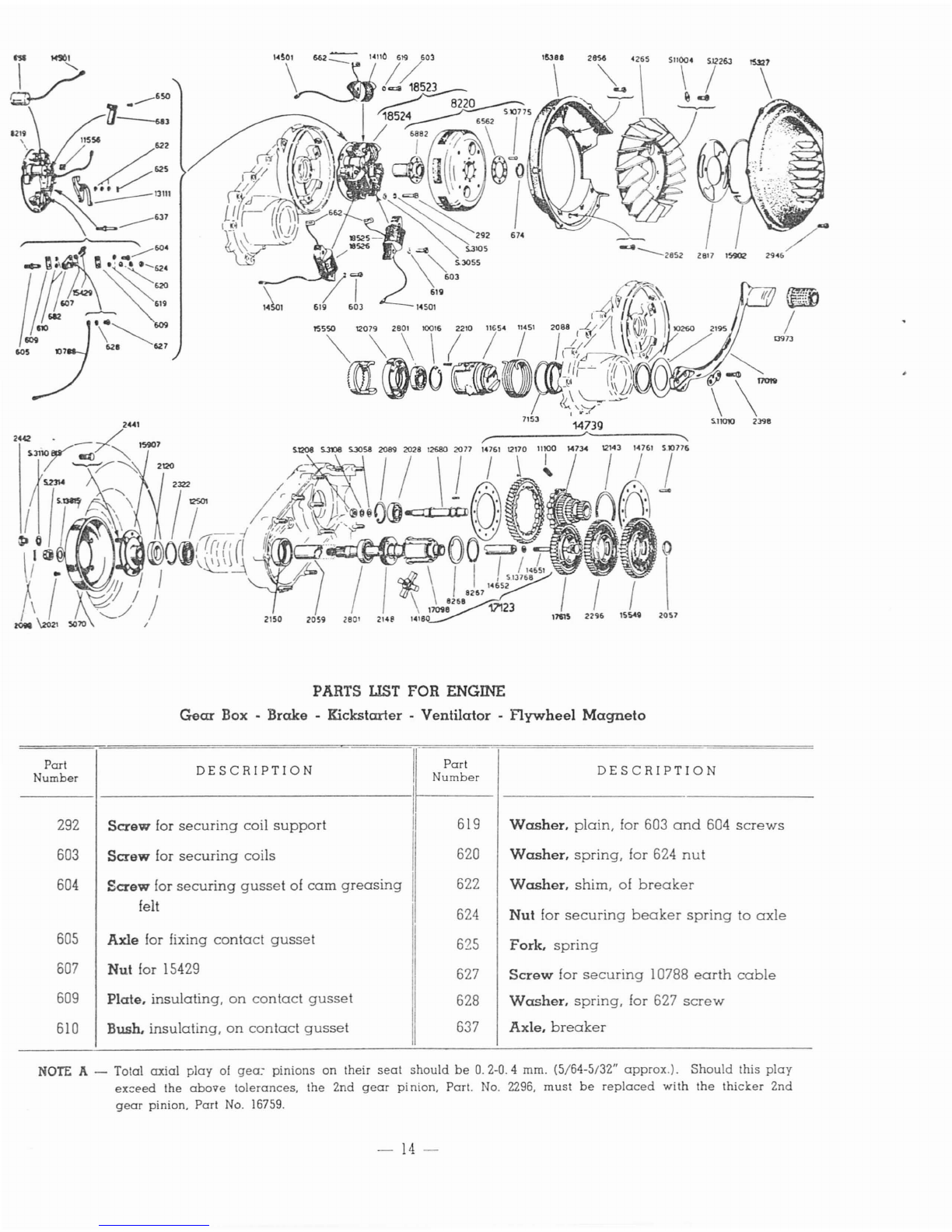
ENGINE
Gear Box -Brake -Kickstarter -Ventilator -
Flywheel
Magneto
Part
DESCRIPTION
I
Part
DESCRIPTION
Number
Number
I
292 Screw for
securing
coil
support
619 Washer.
plain,
for 603
and
604
screws
603
Screw for
securing
coils
620 Washer.
spring,
for 624
nut
604
Screw for
securing
gusset
of
cam
greasing
I622 Washer.
shim,
of
breaker
felt 624 Nut for
securing
beaker
spring
to
axle
605
Axle for fixing
contact
gusset
625 Fork.
spring
607
Nut for 15429 627
Screw
for
securing
10788
earth
cable
609 Plate.
insulating,
on
contact
gusset
628 Washer.
spring,
for 627
screw
610
Bush.
insulating,
on
contact
gusset
637 Axle.
breaker
NOTE
A-Total
axial
play
of
gea~
pinions
on
their
seat
should
be
0.2-0.4
mm. (5/64-5/32"
approx.).
Should
this
play
ex::eed the
above
tolerances.
the
2nd
gear
pinion,
Part.
No.
2296,
must
be
replaced
with
the
thicl::.er
2nd
gear
pinion. Part
No.
16759.
-
14-

PARTS LIST -
Continued
ENGINE
Gear
Box -
Brake
-Kickstarter -
Ventilator
-
Flywheel
Magneto
Part
Number
650
655
662
674
682
683
2021
2028
2057
2059
2077
2088
2089
2098
2120
2148
2150
2195
2210
2296
2322
2398
2441
2442
2801
2801
2817
2852
2856
2946
4265
5070
6562
6882
7153
8219
8220
8267
8268
10016
10260
10788
11100
11451
11556
11654
12079
DESCRIPTION
Rivet for
securing
bolt to
683
gusset
Condenser
Tenuinal,
short
cable,
for coils
Circlip for flywheel
extraction
Gusset
contact
Gusset
of
cam
greasing
felt
Screw
for
joining
brake
drum
to
flange
Ball
Bearing
to
support
multiple
gear
Circlip, small, of
gear
shaft
ball
bearing
(selector
side)
Spacer
of
gear
shaft
ball
bearing
Roller for multiple
gear
Bush,
support,
of 11654
Circlip for
locking
multiple
gear
ball
bearing
Split
pin
for locking
S.
2314
castle
nut
Seal,
spring-loaded,
of
gear
shaft
Ring,
threaded,
for locking
gear
shaft
ball
bearing
Bush for
gear
shaft
ball
bearing
Washer,
seal
locking
Spring
for
starter
bush
Gear,
2nd
speed,
See
note
A
Spacer
between
spring
loaded
seal
and
rear
wheel
ball
bearing
Bolt for
securing
kicks
tarter
Bolt for
securing
wheel
Nut for
securing
wheel
to
drum
Ball
Bearing,
inner
gear
shaft
support
Ball
bearing
to
support
gear
shaft
Cover, inspection, of fan
Screw,
long, for
securing
fan
casing
Screw,
short,'
for
securing
fan
casing
Screw
for
securing
fan
casing
cover
Fan
Drum,
rear
brake
Washer
Cam
Seal,
rubber,
for
starter
bush
Disk, coil
supporting
with inserts
Flywheel
with
cam
(Parts n.
S.
10775 -
6882 -6562
and
rotor)
Circlip
Washer,
shoulder
Circlip,
large,
for locking
2801
ball
bearing
on
slotted
housing
Seal,
felt,
of
starter
assembly
Cable,
earth,
with
terminal
Spring
of
cushion
drive
Spring,
return,
of
kicks
tarter
Grummet
for
electric
cables
on
coil
support
Bush,
starter
Housing
slotted
Part
Number
12143
12170
12501
12680
13111
13973
14110
14180
14501
14651
14652
14734
14739
14761
15327
15388
15429
15549
15550
15902
15907
17019
17098
17123
17615
18523
18524
18525
18526
53105
S.
1208
S.2314
S.
3055
S.3058
S.3105
S.3108
S.
3110
bis
S.
10776
S.
10775
S.11004
S.11010
S.
12263
S.
13768
S.13815
DESCRIPTION
Washer,
shoulder,
of
outer
gear
Gear,
outer
Ball
bearing
outer,
of
gear
shaft
Shaft,
intermediate
Breaker
with
platinum
point
Protection,
rubber,
of kicks
tarter
Coil,
ignition
Selector,
gear
Terminal,
long
cable,
for coils
and
con-
denser
Stem,
selector
Bush,
guide,
of
selector
stem
Gear,
multiple
Drive
cushion,
g.
a.
(Parts
n. 11100 -12170
-12143 -14734 -
S.
10776 -14761)
Washer,
plate,
of
cushion
drive
springs
Cover,
fan
casing
Casing,
fan
Screw,
contact,
with
platinum
p0int
Gear,
low
speed
Ratchet
Ring, elastic, for
inspection
cover
Flange,
female
spline,
with
bolt
Kickstarter
Shaft,
gear
Shaft,
gear,
g.
a.
(Parts
n. 17098 -14652 -
S. 13768 -8268 -14651 -14180 -8267)
Gear.
high
speed
Flywheel
Magneto
wits coil
(Parts
n. 18524
-8220)
Coils,
magneto,
with
support
(Parts n.
14110 -
603
-12549 -619 -12553 -
625-
622 -
13111
-
604
-624 -620 -627 -628
-15429 -607 -682 -610 -605 -11556 -
10788 -
S.
3105 -8219 -609)
Coil.
low
tension
CoiL
low
tension,
Washer,
spring
for
securing
coils
Nut for
securing
intermediate
shaft
Nut,
castle,
for
securing
wheelan
gear
shaft
Washer,
plain,
for 292
screw
Washer.
plain,
for
S.
1208
nut
Washer,
spring,
for 292
screw
Washer,
spring,
for S. 1208
nut
Washer,
spring,
for 2442
nut
Rivet for
securing
plate
washers
Rivet for
securing
cam
to
flywheel
Washer,
tab,
for fan
locking
screw
Plate.
tab,
for kicks
tarter
bolts
Screw,
fan
locking
Washer
Washer,
plain,
for S.2 314
nut
-
15-

----14232
----1423S
14237
~
'\
S.12006
"
PARTS
UST
FOR ENGINE
Carburettor
-Air
Cleaner
-
Gear
Shifter
DESCRIPTION
DESCRIPTION
Part
Number
J
Part
Number
-1----
---1--
__
2121
2489
2506
2508
2600
Screw
lor
securing
gear
shifter to
crank-
case
Pivot of roller
carrying
stirrup
Socket.
low
tension, for
earth
and
lighting
cables
Cap,
rubber,
lor low
tension
socket
Cap,
lastening,
olluel
inlet
pipe
2601
2602
2603
2604
2606
2610
2611
Packing
of
inlet
pipe
Pipe,
fuel
inlet
Filter, fuel
Screw
for
securing
float
chamber
cover
Spring
of throttle
slide
Jet.
maximum
Screw,
adj
uster,
for throttle
slide
-16-

PARTS
UST
-
Continued
ENGINE
Carburettor -Air
Cleaner
-
Gear
Shifter
DESCRIPTION
Packing
for
air
cleaner
Packing
between
air
cleaner
case
and
throttle
cable
support
Atomizer
with
idling
jet
Needle,
taper
Clip for
taper
needle
Rod,
hook,
of
throttle
slide
Slitie,
throttle
Plug,
slotted,
for
hook
rod
Slide,
throttle,
with
hook
rod
(Parts
n.
14232
-
14233
-
14234
-
14235
-
14236)
Cover,
mixing
chamber
Terminal.
pick-up
Rocker,
throttle
cable
Support,
throttle
cable
(Parts
n.
13990
-
13991
-
14577
-
S.
12012
-
S.
3104
-
2748
-
2613
-
2612
-
12340)
Carburetor
with
throttle
cable
support
and
rocker
(Parts
n.
13988
-
14579
-
12338)
Plate,
notched,
of
gear
shifter
Shifter,
gear,
g.
a.
(Parts
n.
4475
-
S.
3206
-
S.
3204
-
2489
-
31515
-
13885-
S.
13010
-
31514
-
31512
-
15370-
13883
-3(517)
Flange,
gear
shift
Lever,
gear
shifting
Roller,
control,
gear
shift
Spring
of
roller
carrying
stirrup
Nut for
securing
intake
pipe
Washer,
spring,
for
2748
crew
Washer,
spring,
for S.
1007
nut
Split Pin
on
13885
pin
Split Pin
on
2489
pivot
Split Pin for
gear
shifting
skid
Nut.
jam,
for
12080
screw
Pin,
taper
Nut for
2748
screw
Split Pin for
securing
outer
wall
Packing
between
pick-up
terminal
and
crankcase
14142
14194
14231
14232
14233
14234
14235
14236
14237
14580
14238
14427
14577
14579
15370
15496
31512
31514
31515
31517
S.1007
S.3104
S.3107
S.
3201
S.
32C6
S.
32G6
S.
12CD6
S.13010
::J.120i2
S.12774
S.
14011
II
Part
Number
DESCRIPTION
Screw,
cable
stretcher
Nut,
jam,
of
cable
stretcher
screw
Tickler
Clip, tickler
Spring, tickler
Cover, float
chamber
Packing of float
chamber
cover
Float
Valve,
needle,
of float
Screw,
clamp
Clamp
Body,
carburetor
Screw,
rocker
Cap,
oil filling
Skid,
gear
shifting
Gauze
Cover,
dust.
between
chassis
baffle
and
intake
pipe
Screw,
locking,
for
12079
slotted
housing
Stud for
securing
air
cleaner
to
carburetor
Support.
throttle
cable
Packing
between
cylinder
and
intake
pipe
Air Cleaner, g.
a.
(Parts
n.
13808
-
100
10
-
S.
12774
-
13803
-
14142
-
13809)
Silencer for
air
cleaner
case
Air Cleaner
with
inserts
Cover,
air
cleaner
Nut.
wing
for
12338
stud
Stirrup,
roller
carrying,
of
gear
shifter
Pin, roller
carrying,
of
gear
shifter
Pipe,
intake
Carburetor,
Dell'Orto
TA
17
B
Type
(with-
out
throttle
cable
support)
(Parts
;
n.
26CO
-
2601
-
2602
-
2615
-
2616
-
2617
-
2603
-
2618
-
2619
-
2620
-
2621
-
2622
-
2623
-
2624
-
2610
-
2611
-
14231
-
14237
-
2606
-
2604
-
14238)
Screw,
stop,
of throttle
slide
Spring for
13990
screw
Part
umber
2612
2613
2615
2616
2617
2618
2619
2620
2621
2622
2623
2624
2748
2990
4475
10010
11249
13990
13991
12080
12338
12340
12358
13800
13803
13808
13809
13830
13883
13885
13944
13988
----l------------Ii
I
I
I
I
I
'I
I'
;1
'I
I,
II
II
I
I
I
I
I
I
I
I
i
-17-

19262
C/1f~
~
\
19816
'"
---
.
~~JJ1:
1
19378
"111
117511
17021
PARTS
LIST
FOR CHASSIS
'Fuel Tank -
Saddle
-Tool Box -Bonnet
Part
Number
DESCRIPTION
Part
Number
DESCRIPTION
2319
2383
2917
2939
2940
2941
2944
3142
3221
3663
3979
4433
4435
5082
9433
9640
9641
10055
10984
11032
11128
11166
11177
11242
Packing of filler
cap
Washer, plain, for
S.
1008
nut
(rear)
Pivot, hinge, of
carburetor
side
shutter
Lever, lock,
of
tool
box
shutter
Spring of tool
box
shutter
Pin for 2939 lock
lever
Pivot, hinge,
of
tool
box
shutter
Rivet for
securing
lock
on
engine
bonnet
Strap,
pipe
fastening
Rivet for
securing
12115
basin
Packing
between
chassis
and
fuel
tank
Pivot
Screw, tie, of filler
cap
Rivet for
securing
13481
hinge
Nut for
securing
fuel
tap
Cup, settling, of
gasoline
strainer
Fastener of
settling
cup,
with
inserts
Nut, wing, for filler
cap
Pin, lower, for
securing
front
spring
to
saddle
Rivet for joining
support
gussets
of
saddle
Spring, return, of
carburetor
side
shutter
Lock
of
engine
bonnet
Spring, wire, for 11728 frame
Gusset,
connection
11299
11580
11653
11728
11751
11752
11760
12115
12154
12218
12219
12742
13481
13613
13614
13618
13820
13821
13835
13836
13876
13879
Wire,
connection,
between
lever
and
strangler
Lever,
strangler
control
Hook,
purse
hanging
Frame,
hinge
carrier,
of
engine
bonnet
Strip,
rubber,
for
engine
bonnet
Strip,
rubber,
for tool
box
Buffer,
stop,
of
carburetor
side
shutter
Drip
pan
for
outflowing
fuel
mixture
Washer,
support
of
package
carrier
Spring
for
supporting
canvas
roll
Hook
for
canvas
roll
support
springs
Shutter, tool
box,
with
inserts
Hinge, for
engine
bonnet
Gusset,
saddle
support
Spring,
conical,
rear
left
hand
side
Pivot for
joining
11242
gusset
to
saddle
frame
Gusset,
spring,
for locking fuel
tank
Buffer,
rubber.
for 13820
spring
gusset
Flange
Packing
between
fuel
tap
and
threeway
cover
Filter, fuel,
with
inserts
Clip,
spring,
of fuel filter
-
18-

PARTS LIST -
Continued
CHASSIS
Fuel
Tank -
Saddle
-Tool Box -Bonnet
Part
Number
13963
14162
15011
15012
15098
15123
15464
15466
15467
15900
16724
16764
16779
16994
17021
17170
17337
17338
17402
17532
18474
18946
19262
19268
19269
19271
DESCRIPTION
Spring, conicaL
rear
right
hand
side
Tank, fueL
with
inserts
Tap,
fuel
Washer,
plain,
for
9433
nut
Sheath,
rubber,
for
15464
control
rod
Pipe,
rubber,
from
gasoline
strainer
to
carburetor
Rod, fuel
tap
control
Cover,
three-way
Split Pin for
15464
control
rod
Tap, fueL
with
gasoline
strainer
(Parts
n.
9433
-
15012
-
15013
-
S.
10011
-
13835
-
15011
-
13836
-
9638
-
13876
-
13879
-
9640
-
9641
-
15466
-
15464
-
15467)
Cap,
filler, of fuel tank,
with
inserts
Packing for
gasoline
strainer
Packing
between
fuel
tap
and
tank
Carrier,
package
Tank, fueL
with
tap
and
filler
cap
(Parts
n.
2319
-
4433
-
10053
-
10055
-
4435
-
S.
3212
-
14162
-
15098
-
15900)
Saddle,
complete
Holder,
rear
license
plate
Plate, for
license
plate
holder
Spring, front of
saddle
Plate,
name
«
Allstate»
Transfer,
indicating
gas-oil
ratio
of fuel
Buffer,
rubber,
for
bonnet
lock
Chassis
of
motor-scooter,
with
inserts
Shutter,
carburetor
side
Plate,
number,
on
carburetor
slide
shutter
Washer
under
wire
springs
Part
Number
19378
19816
S.
1004
S.
1006
S.1006
:S.1008
S.II05
I
S.
3058
S.3105
S.3106
S.3106
S.
3204
S.
3208
S.3212
S.IOOII
S.
IOD26
S.
10762
S.
10770
S.10781
S.
12259
S.
12273
S.
13760
S.
13763
S.
13793
S.
13829
DESCRIPTION
Bonnet,
engine,
with
inserts
Box, tooL
with
shutter
(Parts
n.
12742
S.
3204
-
2944
-
2939
-
2941
-
2940)
Nut for
S.
12273
bolt
Nut
on
10984
pin
Nut
for
securing
13481
hinge
to
11728
frame
Nut for
securing
saddle
Nut
Washer,
plain,
for
13618
pivot
Washer, lock
Washer,
spring,
on
10984
pin
Washer,
spring,
for
S.
1006
nut
Split pin,
on
2944
hinge
pin
Split Pin for
13618
pivot
Split Pin for
supporting
tie
screw
Screw
for
securing
13835
flange
Screw,
upper,
for
securing
front
spring
to
saddle
Rivet for fixing
11751
rubber
strip
and
18946
buffer
Rivet for
securing
11728
frame
to
engine
bonnet
Rivet for
19269
name
plate
Bolt, for
license
plate
holder
Bolt~rsecuring~clbox
Washer,
plain
Plate,
strengthening
Washer,
plain,
for S.
1004
nut
Washer,
plain,
for
rivets
securing
name
plate
-
19-

~=
~-'
~--
..
"
0--J:HtO
~----S.Dl'l1
~~=
PARTS
LIST
FOR CHASSIS
Silencer
-
Engine
Bracket -Rear
Suspension
-Strips
Part
Number
61
2035
2036
2040
2083
2444
2957
3135
3197
5943
6281
6285
6290
6291
6293
6294
6295
6297
6359
DESCRIPTION
Clip,
spring,
for
brake
jaws
Link.
rear
brake
Bolt
for
securing
cable
to
Adjusters
of
rear
brake
and
clutch
control
cables
Pin
for
rear
brake
links
Nut.
jam.
for
rear
brake
and
clutch
adju-
sters
Bolt
for
securing
stand
fastener
Rivet
for
securing
brake
lining
Spring,
return,
of
brake
jaws
Plate,
upper.
for
17432
spring
Anchorage,
bottom,
of
rear
suspension
Nut.
spacer
of
shock
absorber
Pin.
anchoring,
for
shock
absorber
Washer,
spacer
Spring,
upper
Circlip
Spring
of
seal
washer
Spacer,
bottom
Bush,
bottom,
rubber,
of
shock
absorber
Part
Number
6360
7881
7884
7886
7888
7890
12403
12404
13406
14836
14850
15008
16852
16995
16996
17012
17013
DESCRIPTION
Bush,
top,
rubber,
of
shock
absorber
Jaw,
brake,
with
lining
Arm,
rear
brake
control
Pad
Axle.
cam,
of
rear
brake
Lining,
brake
Spring,
return,
of
stand
leg
(right
hand
side)
Spring,
return,
of
stand
leg
(left
hand
side)
Tube,
protection,
of
shock
absorber.
with
inserts
Buffer,
stop,
of
engine
bracket
Silencer
Shoe,
rubber,
for
center
stand
Washer,
thrust,
for
32690
packing
Packing
between
16996
anchorage
and
chassis
Anchorage,
top,
of
rear
suspension
Leg
stand,
with
shoes,
g.a.
(Parts
n.
15015
-
17013
-
15008)
Leg,
stand,
with
inserts
-
20-
This manual suits for next models
2
Table of contents
Other Allstate Scooter manuals


Popular Scooter manuals by other brands


Razor
Razor Graffiti owner's manual

Nils Extreme
Nils Extreme Fliker 14619 user manual

Pride Mobility
Pride Mobility Mini Crosser owner's manual

Shoprider
Shoprider mobility scooter user guide

Olsson and Brothers
Olsson and Brothers STROOT BONNEVILLE 5 User guide and guarantee

Helvei
Helvei Smartmove ALLROAD user manual