ALLTEC TerraStreamer TSP-20 Datasheet

TerraStreamer®
Early Streamer Emission Terminals
Installation Instruction Guide
MODELS: TSP-20 | TSP-30 | TSP-40 | TSP-50 | TSP-60 | TPV-60

2 3
TerraStreamer®Early Streamer Emission (ESE) Terminals
Installation Guide
Table of Contents
Warranty............................................................................................... 2
Supplied Items..................................................................................... 3
TerraSteamer®Early Streamer Emission (ESE) Terminals.................. 4
Features..................................................................................................................................4
Protection Performance ...................................................................................................5
Protection Radius - Additional Levels..........................................................................5
Positioning & Height............................................................................ 6
TerraSteamer® ESE Terminal ............................................................................................6
Preferred Installation Points............................................................................................6
Pre-Installation Checklist .................................................................................................7
Important Safety and Other Considerations.............................................................7
Ground System Congurations .....................................................................................8
1. Installation of the Grounding System............................................. 8
Down Conductor Routing Guidelines.........................................................................9
Number of Down Conductors and Grounds.......................................................... 10
Adaptor................................................................................................................................ 10
2. Down Conductor Installation........................................................ 11
3. Termination of the Down Conductor............................................ 12
Lower End........................................................................................................................... 12
Upper End........................................................................................................................... 13
4. TerraStreamer®ESE Terminal Installation .................................... 14
Guyed FRP Masts.............................................................................................................. 14
Metallic Masts.................................................................................................................... 16
5. Lightning Strike Counter Installation............................................ 17
6. TerraStreamer® ESE Post Installation Verication ....................... 18
7. Inspection/Maintenance............................................................... 18
Schedule ............................................................................................................................. 18
Checklist.............................................................................................................................. 18
Disclaimer .......................................................................................... 19
Warranty
The warranty is limited to the cost of replacement of equipment providing it has
been installed and/or certied by Alltec or its authorized distributor. Alltec shall
in no event be responsible for any loss of business or prots, downtime or delay,
labor, repair or material costs or any similar or dissimilar consequential loss or
damage incurred by the buyer. All other costs such as: insurance premiums,
freight charges, loss of prot, and re-installation of equipment are not included.
Also specically excluded from the warranty is any responsibility for other direct
or indirect damages, injuries or death.
NOTE: Alltec shall in no event be responsible if the products have
not been stored or used in accordance with its specications and
recommended procedures.
Do not attempt to install lightning protection components or systems
during periods of lightning activity!

3
Supplied Items
WARNING
THERE IS A SAFETY ADVISORY
AGAINST STANDING WITHIN A
PROXIMITY OF 12 FEET (4 METERS)
OF THIS LIGHTNING PROTECTION
SYSTEM WHILE AN ELECTRIC STORM
TerraStreamer® TSP
ESE Terminal Adaptor
Warning Label (2)
Warranty Card
WARRANTY REGISTRATION AND STATEMENT OF COMPLIANCE
The warranty is limited to the cost of replacement of equipment providing it has been installed and/or certified by ALLTEC or its authorized
distributor. ALLTEC shall in no event be responsible for any loss of business or profits, downtime or delay, labor, repair or material costs or
any similar or dissimilar consequential loss or damage incurred by the buyer. All other costs such as: insurance premiums, freight charges,
loss of profit, and re-installation of equipment are not included. Also specifically excluded from the warranty is any responsibility for other
direct or indirect damages or death. ALLTEC shall in no event be responsible if the products have not been stored or used in accordance with
its specifications and recommended procedures (See complete warranty statement for further details).
TerraStreamer®products require project specific lightning protection design and installation. Inappropriate use of these products, or use
in designs not provided by or approved by ALLTEC will invalidate performance characteristics and all Warranty Provisions.
TerraStreamer®ESE Terminals are guaranteed against defects in workmanship and materials for a period of 5 years from the original date
of sale when purchased from ALLTEC or one of its authorized distributors. TerraStreamer®ESE Terminals shall be installed and used only
as indicated in ALLTEC’s product installation manual and according to UNE 21 186 or NF C 17-102 standards. Improper installation,
mishandling, misapplication or other failure to completely follow ALLTEC’s instructions and warnings may cause product malfunction,
property damage, serious bodily injury or death. TerraStreamer®systems should only be installed during storm free periods.
Neither TerraStreamer®ESE systems nor any other lightning protection system can provide 100% protection from lightning. We refer to
the French Standard NF C 17-102: “As in the case with anything related to the natural elements, a lightning protection system designed and
installed in accordance with the standard, cannot guarantee absolute protection to structures, persons or objects: however, applying this
standard will significantly reduce the risk of protected structures being damaged by lightning.”
System Installed - Model Type:
Serial #s:
# of Terminals:
Type, size and length of down conductor:
Protective Radius Obtained:
NF C 17-102
UNE 21 186
Ground Resistance Reading:
Failure to perform installation and maintenance as per Alltec’s recommendations automatically
voids all warranty conditions.
For Warranty registration, please complete the above and mail to ALLT EC within 30 days of installation (see reverse side)
Name of Project:
Address:
Type of Structure:
Installation Date:
Installation Contractor:
Inspected by:
Inspection Date:
Alltec Distributor:
Important Notice:
TerraStreamer®ESE System Project Information
WARNING
WARRANTY
Quality Certificate (Front)
Warranty Statement (Back)
www.alltecglobal.com
ALLTEC - Solution Providers for an EnergizedWorld | 64 Catalyst Drive | Canton, North Carolina 28716 USA | +1.828.646.9290
© 2014 ALLTEC
QUALITY CERTIFICATE
Quality Control Verification Parameters:
TSP-20
Company Stamp:
Signed: Date:
Triggering Time Advance (∆T) = 22µs Accredited High Voltage Testing:
Product Assembly Verification:
Packaging Quality Verification:
Installation Guide Supplied:
Warning Labels (Qty 2) Supplied:
Warranty Certificate Supplied:
Results & Serial Number Archived:
TSP-30
Triggering Time Advance (∆T) = 32µs
TSP-40
Triggering Time Advance (∆T) = 44µs
TSP-50
Triggering Time Advance (∆T) = 55µs
TSP-60
Triggering Time Advance (∆T) = 61µs
Serial No:
Model:
TerraStreamer®
EARLY STREAMER EMISSION TERMINALS
This is to certify the above product is manufactured to a design achieving a triggering time (ΔT) as
stipulated above in accordance with NF C 17-102 and UNE 21 186.
This document further certifies that this unit meets or exceeds all Quality Control parameters as
established by Alltec, and that Electrical Testing according to the above International Standards has
independently verified performance, as documented by a fully Accredited Laboratory.

4 5
TerraStreamer®Early Streamer Emission (ESE) Terminals
The TerraStreamer® ESE Lightning Terminal is an externally mounted, proactive,
structural lightning protection device and is designed to activate itself in the
moments directly preceding an imminent direct strike. The installation of a
TerraStreamer® ESE Terminal combines the best advantages of two systems: the
direct path to ground of a conventional lightning protection system, and state-
of-the-art ESE technology employed in the TerraStreamer®’s internal design.
TerraStreamer®ESE Terminals are designed to react to the rise in the ambient
electrical eld which is present with approaching thunderstorms, and become
active only during storm activity.
• The system operates without the need for external power supply or spare
parts for standard operation.
• To keep the TerraStreamer®ESE Lightning Protection System operating at
optimum levels it needs to be maintained and inspected regularly.
Features & Benets
• Patented Technology
• NF C 17-102 and UNE 21 186 tested and certied
• Lightweight and low wind loading
• Reliable performance in all weather conditions
• Suitable for corrosive environments
• Available in ve models for numerous applications
• Economical and easy to install
• No internal electronics or power supply
TYPICAL APPLICATIONS
• Distribution Warehouses
• Industrial Plants
• Apartment Buildings
• Shopping Malls
• Shipping Terminals
• Other Large Area Structures

5
Protection Radius Additional Levels
Level 1+:
The ESE system at level of protection
1 is additionally connected to the
metal structure or reinforced bars
of the buildings used as natural
downconductors in addition to the
dedicated downconductors included
in the ESE system. Connection to
the natural downconductors shall be
made at roof level and ground level.
Level 1++:
The roof is protected at level 1+ with
an ESE having a radius of protection
reduced by 40% compared to achieve
a complete protection of equipments
on the roof against direct lightning
strikes.
Protection Performance
Protection Areas
H(m) TSP-20
(Rp)
TSP-30
(Rp)
TSP-40
(Rp)
TSP-50
(Rp)
TSP-60
(Rp)
Level I
2 16 20 25 30 32
3 24 30 37 44 48
4 31 40 50 59 63
5 39 50 62 73 79
6 40 50 62 74 79
8 40 51 63 74 79
10 41 51 63 74 80
Level II
2 18 23 28 32 35
3 27 35 42 48 52
4 36 47 55 64 70
5 45 58 69 80 87
6 47 58 69 80 87
8 47 59 70 81 88
10 48 60 71 81 88
Level III
2 22 27 32 37 39
3 33 40 48 56 59
4 43 53 64 74 78
5 54 66 80 92 97
6 54 66 80 92 98
8 56 68 81 93 99
10 57 69 82 94 99
Level IV
2 25 30 36 41 43
3 37 45 53 61 64
4 49 59 71 81 86
5 61 74 88 101 107
6 62 74 89 102 107
8 63 76 90 103 108
10 65 77 91 104 109
The standard protection radius Rpof the TerraStreamer®is linked (according to
NF C 17-102 standard) to ΔT, to the protection levels I, II, III, or IV and to the
height of the TerraStreamer® above the protected structure (H, dened by NF C
17-102 as a minimum of 2 m). The NF C 17-102 standard includes four levels of
protection.
Upward Streamer
TerraStreamer®
Rp h

6 7
Positioning & Height
TerraSteamer® ESE Terminal
The TerraSteamer® ESE Terminal tip should be at least 2 meters higher than the
area that it protects, including antennae, cooling towers, roofs, tanks, etc.
If the external installation for a given structure comprises several ESE Terminals
these are to be interconnected by a suitable conductor, unless it has to be
routed over a structural obstacle (cornice, parapet wall) with a positive or
negative level difference in excess of 1.5m (see Fig. A).
When ESE Terminals protect open areas such as playing elds, golf courses,
swimming pools, camping sites, etc., they should be installed on specic
supports such as tower mast, lightning poles, pylons, or any other nearby
structures which enable the ESE Terminal to cover the area to be protected.
The ESE Terminal height may be increased by means of an elevation mast. If the
ESE Terminal is steadied by conductive guy lines, these should be connected
at the bottom attaching points to the down conductors by means of suitable
conductors.
Preferred Installation Points
The architectural features favorable to the ESE Terminal installation should be
taken into account during the lightning protection system design.
Usually, these features are high structural points, such as:
• equipment rooms on at roofs
• gables
• metal or masonry chimneys
< 1.5m < 1.5m
≥2m ≥2m
Fig. A - Positioning & Height

7
Pre-Installation Checklist
Determine the best location for ESE Terminal(s), then the mounting method
(tower, mast, structure, etc.) and the optimum routing of down conductor(s).
Locate area(s) for grounding system installation and determine where the
new system will be connected to any existing grounding system and metal
bodies of conductance, etc.
Verify that all parts and system components are compatible (dissimilar
metals not allowed) and in good condition.
Review installation plans, structural drawings, site drawings and mast
erection instructions.
Read this Installation Guide and familiarize yourself with all of the system
components and functions.
Be sure that all tools and equipment required for system installation are
available and in good working order.
Follow all industry guidelines and local/site requirements for safety and
safety equipment.
Important Safety and Other Considerations
• If the TerraStreamer®ESE Terminal needs to be erected prior to connection
to the grounding system, or immediate connection is not possible, connect
the lower end of the down conductor to structural steel reinforcing or other
suitable grounding point.
• Before installation of the grounding system, consult site drawings of
underground services so that these are not damaged during installation of
the grounding system.
• Where separate grounding systems exist, i.e.: structure, power,
communications and/or lightning protection, they need to be bonded
together to form an equipotential ground plane. This will help prevent
ground potential differences arising under direct/indirect lightning strikes.
• Before service ground bonding takes place make sure proper authorization
is obtained.
• Bonding cable must be 70mm2 (2/0AWG) minimum, depending on local
standards. It may be necessary to use a grounding bus bar which bonds all
grounds to the same potential under transient conditions.
• All local applicable standards, regulations and requirements necessarily
apply.
• It is the responsibility of the customer/installer to label inspection/test wells
or grounding systems to local requirements.
Stay clear of any overhead power lines.

8 9
Ground System Congurations
A ground resistance of less than 10Ωis required for proper operation of the
TerraStreamer® ESE Terminal. If, due to space constraints or high soil resistivity,
it is not possible to readily install a grounding system as recommended,
alternate grounding methods and designs shall be considered.
In order to meet safety and grounding system resistance requirements, Alltec
recommends the installation of a purpose designed and installed grounding
system such as the radial (crow’s foot) design or Delta design. Other
congurations and materials are allowed, and may be required due to local
conditions.
NOTE: Alternate grounding methods and designs are allowed by NF C
17-102, and Alltec is capable of designing a grounding system to meet
specic resistance goal in any type of soil.
DD
P
P
B
B
D: Down-conductor
B: Building foundation loop gr
ound
P: Grounding system
Radial Delta
Fig. B - Recommended Grounding Congurations
1. Installation of the Grounding System
Each radial should consist of a trench (approx. 50cm deep x 20cm wide x
10m length).
A ground rod should be driven at the end of each radial.
The use of copper conductor is recommended, with a cross sectional area
of not less than 50mm². Tin-plated copper is recommended for its corrosion
resistance.
All rods should be interconnected through the use of 1/0-19 strand bare
conductor and ground rod clamps or TerraWeld® exothermic welding. The
use of the TerraWeld® exothermic welding process is a safe and efcient
way of providing a permanent connection between conductors. TerraWeld®
connections will not rust or corrode over time.
ESE Grounding Systems should utilize TerraDyne® Electrolytic Ground
Electrodes and TerraFill® ground enhancement backll to provide the
desired low resistance ground system and stabilize low contact resistance
at locations where the native soil has relatively high resistivity, low ground

9
moisture and/or where installations have limited footprints.
A ground inspection/test well should be installed where the end of the down
conductor terminates to the grounding system. This gives an access point
for disconnection and future testing.
Each down conductor should be provided with a means of disconnect for
testing. These disconnect/test terminals may be located 2m above ground
level and should be marked “Lightning Conductor” and the symbol:
When the building or the protected structure has a foundation earth
termination system for the electrical system, the ESE system earth
termination systems should be connected to it with a standardized
conductor.
The ESE system earth termination components should be at least 2 m
distant away from any buried metal pipe or electrical conduit, in case these
conduits are not electrical connected to the main equipotential bonding of
the structure.
Down Conductor Routing Guidelines
Bare or tin-plated copper conductor is recommended for use as the down
conductor, although building steel and alternate materials are also allowed. NF
C 17-102 requirements should be strictly adhered to as regards materials and
design requirements for number and placement of TerraStreamer®ESE Terminals
and down conductors.
• The route of the down conductor should be as set out in the original design.
Ensure no structural changes such as new antenna, mast installations, air
conditioning towers or ducting has been installed.
• DO NOT double the down conductor back against itself after changes of
direction (i.e. 180° bend).
• The down conductor may be installed internally or externally on the
structure; however internal routing may reduce effectiveness and induce
voltage surges into structures.
• The down conductor should be installed as close (ush) as possible to the
structure.
• Minimize the number of bends and use the most direct route to the ground
possible.
• Ensure recommended bend radius is maintained, never less than 20cm.
• If the down conductor has to cross other services make sure it crosses at
right angles using a conduit that extends at least 1m past either side of the
existing service.
• The down conductor should be protected from damage at the lower end by
installing a protective tube/conduit up to 2m from ground level.
• Provide adequate separation between down conductors, preferably
opposite building corners.

10 11
Number of Down Conductors and Grounds
For a non-isolated ESE system, each terminal should be connected to at
least two (2)down conductors. For a better current distribution, the two paths
to ground should be situated on two different facades. If, due to physical
constraints, it is not possible to route the down conductors on two different
facades, an alternate installation method should be considered.
When many ESE terminals are located on the same building, the down
conductors shall be mutualized on a case by case basis, but a minimum of one
down conductor is mandatory for each ESE terminal.
When a natural component of a structure is utilized as a down conductor,
at least one of them must be a dedicated down conductor complying with
standard requirement.
In case of an isolated ESE system, at least one down conductor is needed for
each ESE terminal.
Adaptor
Down conductors should be attached to the TerraStreamer®ESE Terminal using
the supplied adaptor as per Fig. D , and as recommended in sections following.
Fig. D - Adaptor

11
2. Down Conductor Installation Guidelines
Bare or tin-plated copper conductor is recommended for use as the down
conductor. The route of the down conductor should be as set out in the
original design. Ensure no structural changes have been implemented.
The use of copper conductor is recommended, with a cross sectional
area of not less than 50 mm². Tin-plated copper is recommended for its
corrosion resistance.
The copper should be of a grade normally used for commercial electrical
work. Do not use insulated coaxial cable.
The most direct path to ground is recommended, avoiding sharp bends.
Minimize the number of bends and use the most direct route to the ground
possible.
Ensure recommended bend radius is maintained, never less than 20 cm.
DO NOT double the down conductor back against itself after changes of
direction (i.e. 180° bend).
The down conductor should be installed as close (ush) as possible to the
metal tower.
If the down conductor has to cross other services make sure it crosses at
right angles using a conduit that extends at least 1m past either side of the
existing service.
Suitable fasteners should be installed to secure all down conductors. Down
conductors should be fastened on the basis of one point per meter. Avoid
trip hazards
Each down conductor should be connected to the grounding system.
The Warning Labels supplied with TerraStreamer®ESE Terminals should be
installed in locations where personnel may be in close contact to the down
conductor(s).
Down Conductor
Do not exceed minimum
bend radius.
Mast
Mast Base
Fastener
Roof Edge
Fig. E - Down Conductor Routing Detail
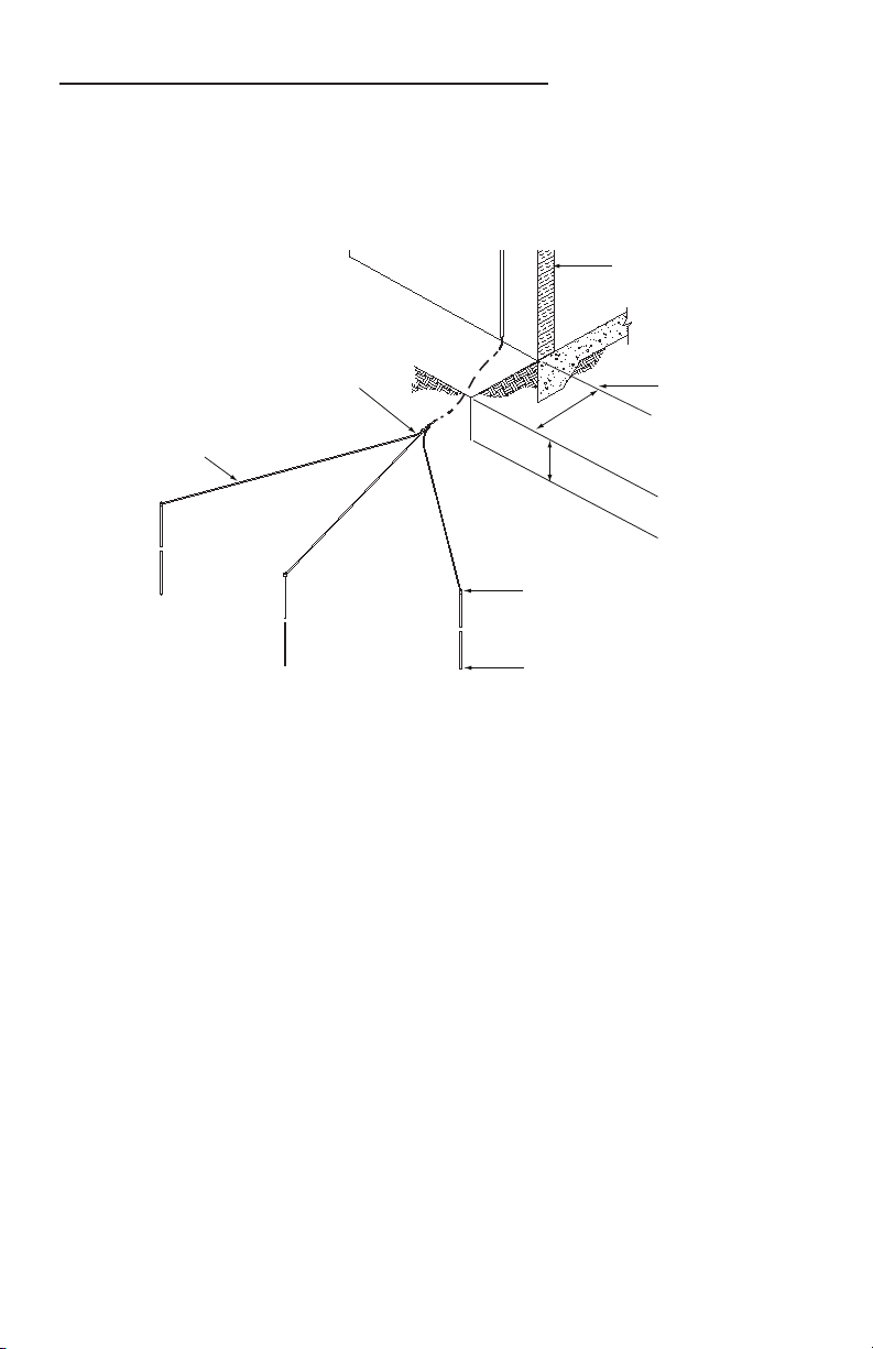
12 13
3. Termination of the Down Conductor
Lower End
Down conductor(s) should be directly connected to the grounding system
through the use of a suitable ground rod clamp or by using TerraWeld®
exothermic welding.
Exterior Wall
1m Minimum
Ground Rod Clamp or
Exothermic Weld
Ground Rod
Minimum 16mm Diameter x 3m length
50cm Min.
Finished grade
Cable Splicers or
Exothermic Welds
Three Radials
2m - 10m long
Fig. F - Down Conductor Lower End
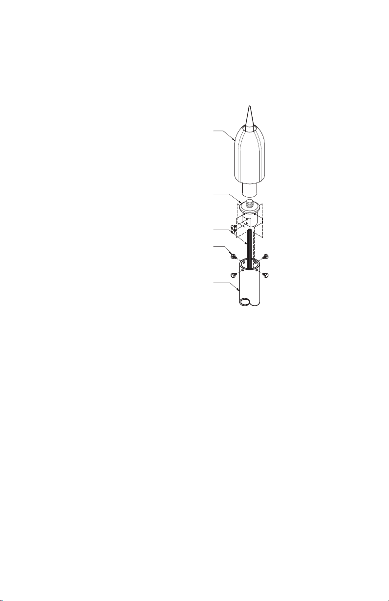
13
Upper End
Each TerraStreamer®ESE Terminal comes supplied with the adaptor (Fig. G).
This adaptor accepts either stranded copper wire, or at copper strip.
• Round/stranded copper wire is inserted into the hole in the base of the
adaptor and secured with the two screws provided.
• Flat copper strip attaches to the external “at” side of the adaptor.
TerraStreamer®
ESE Terminal
Stainless Steel TSP to
Mast Adaptor
Down Conductor
Stainless Steel Set Screw-Type
Ø2” Tower Mast
Fig. G - Down Conductor Upper End
14 15
4. TerraStreamer®ESE Terminal Installation
Stay clear of any overhead power lines or electrical sources.
When installing the TerraStreamer® ESE Terminal, Alltec provides for two main
conguration types.
Guyed FRP Masts
When installing the TerraStreamer® ESE Terminal with an Alltec FRP mast,
refer to the supplied FRP Mast Installation Guide for assembly and installation
instructions. Other important items to remember include:
Using a crane or other suitable equipment is recommended for any
installation over 6 meters in height, or for hazardous areas such as unsafe
heights without appropriate safety railings.
It is very important to keep the mast straight during the lift to avoid
damaging the mast.
The TerraStreamer®ESE Terminal must NOT be used as a slinging point.
When lifting masts, ensure that the slings or ropes cannot damage the
TerraStreamer®ESE Terminal.
When lifting the mast, the down conductor must be tied off to the
mast to remove any strain on the down conductor’s termination to the
TerraStreamer®ESE Terminal and/or supplied adaptor.
The TerraStreamer® ESE Terminal tip must be at least 2m above any aerial,
equipment or structure on the roof. Please refer to NF C 17-102 standard or
Alltec design for specic mast/ESE height requirements.
Guy wires must be tight, but also consider roof load limitations (e.g. tighten
guying grips to no more than 7 Nm of torque).

15
Installation Examples Using FRP Masts:
TerraStreamer®
ESE Terminal
Strike Counter
Inspection Well
Grounding System
FRP Mast
Mast Base
Guy Ring
Guy Wire
Fig. H - Mid Roof location
TerraStreamer®
ESE Terminal
Strike Counter
Inspection Well
Grounding System
FRP Mast
Mast Base
Guy Ring
Guy Wire
Fig. I - Edge Location

16 17
Metallic Masts
Following installation of the TerraStreamer® ESE Terminal to a metallic mast,
it will be necessary to connect the metallic mast to a down conductor in
order to convey the lightning energy to the grounding system.
The connection between the metallic mast and the appropriately sized down
conductor should be completed by approved mechanical means or by
exothermically welding (TerraWeld®) the down conductor at a practical point
somewhere along the length of the mast.
Particular care should be taken to ensure that compatible metals are used
when connecting the down conductor to metallic masts (e.g. aluminum to
copper connections require an approved bimetallic connector).
It is important that a minimum of one third of the mast height be securely
xed to the structure to which the mast is mounted.
Installation Examples Using Metallic Masts:
TerraStreamer®
ESE Terminal
Down Conductor
Tower Section 2
Fasten 3’-0” Max. SP.-TYP.
Tower Section 1
System Disconnect
PVC Inspection Well
Copper
Clad Ground
Electrode-
TYP 3X
Tower
Base
Fig. J - ESE - Tower Mast Detail

17
TerraStreamer®
ESE Terminal
Metallic Mast
Stainless Steel Cable Ties or
Mounting Brackets
Strike Counter
Inspection Well
Fig. K - Tower Top Location
5. Lightning Strike Counter Installation
The Lightning Strike Counter should be installed at a position along the
down conductor length where it can be accessed easily for inspection.
Typically the strike counter should be installed approximately 2m from
ground level.
The strike counter should be mounted away from areas where damage/loss
may occur due to theft, vandalism or damage from nearby operations.
The strike counter can be enclosed in a security enclosure but the display
should be kept visible to allow for the checking of recorded strikes.

18 19
6. TerraStreamer® ESE Post Installation Verication
The following should be checked for quality of workmanship and compliance to
recommended installation instructions, approved design documents, and NF C
17-102/UNE 21 186 requirements:
Correct TerraStreamer®ESE Terminal model and placement for proper
zone of protection (verify model, height above structures, and radius of
protection).
Correct mast and any associated brackets and fasteners have been used
for installation.
Guying, anchor points and fastenings (if applicable).
Down conductor size, routing, and attachment points
Connection of down conductor to grounding system
Grounding system (3-Point resistance test to verify 10 Ohms or less)
Lightning Strike Counter installation is per recommended guidelines. Record
“strike count” for later comparison.
Safety and product labeling
7. Inspection/Maintenance
Alltec recommends inspection and any required maintenance to be performed
regularly and as listed below:
Schedule
• After each known lightning strike to the terminal.
• Once every twelve months minimum.
• If changes have been made to the protected structure.
Checklist
Check Lightning Strike Counter “strike count”, and compare to previous
display number.
Check Lightning Strike Counter installation for missing/damaged wires and
connections.
Check the strike counter for secure installation and record the number of
strikes, if any.
Check for any damage to the TerraStreamer® ESE down-conductor and
grounding system.
Check TerraStreamer® ESE Terminal body and tip for excessive pitting or
other damage.
Inspect the TerraStreamer® ESE Terminal and ensure that no dirt or
other matter is embedded in the air gap between the center tip and the
surrounding panel edges.
Verify that the structure to be protected has not been modied or expanded
since the last maintenance check.
Make sure that the electrical continuity of all visible conductors is correct,

19
and that no conductors or other parts have been weakened by corrosion.
Check that all rigging, mast mounts, and conductor xings are secure and
tight.
Check that all down conductors and equipotential bonds remain correctly
positioned and that they are securely attached and no damage or theft has
occurred.
All warning labels must still be in place and visible.
Disclaimer
Alltec TerraStreamer®Lightning Protection for Structures and Open Areas
Using Early Streamer Emission (ESE) Technology
“As in the case with anything related to the natural elements, lightning protection
systems, designed and installed in accordance with this standard, cannot
guarantee absolute protection to structures, persons or objects: however,
applying this standard will signicantly reduce the risk of protected structures
being damaged by lightning.” NF C 17-102 (Forward)
Neither the TerraStreamer®ESE Terminal nor any other lightning protection
system to our knowledge can provide 100% protection from lightning.
In order to provide the most effective Early Streamer Emission (ESE) Air
Terminal technology available today, Alltec TerraStreamer®ESE Terminals are
independently tested and certied to meet NF C 17-102 and UNE 21 186
standards. In addition, these modern standards have provided the applicable
information contained in this Installation Guide to correctly implement a proper
ESE system.
The NF C 17-102 and UNE 21 186 standards are “applicable to lightning
protection using early streamer emission lightning conductors of common
structures of less than 60m high and of open areas.” It is recommended that
any ESE installation strictly adhere to the general and detailed contents of
the latest editions of the NF C 17-102 and UNE 21 186 standards.
Alltec has developed the TerraStreamer®product according to
internationally recognized standards. However, Alltec does not make any
specic performance guarantees as no lightning protection system can be
100% eective.

www.alltecglobal.com
WORLD HEADQUARTERS
64 Catalyst Drive, Canton, North Carolina 28716 USA
TEL: +1.828.646.9290 | FAX: +1.828.412.4270
EMAIL: [email protected]
© 2017 ALLTEC | 420-001 | 11/22/2017
This manual suits for next models
5
Table of contents


