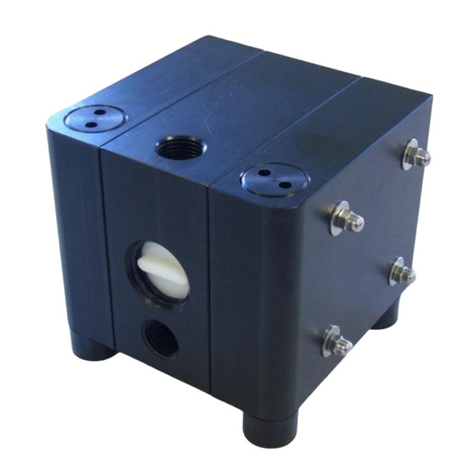
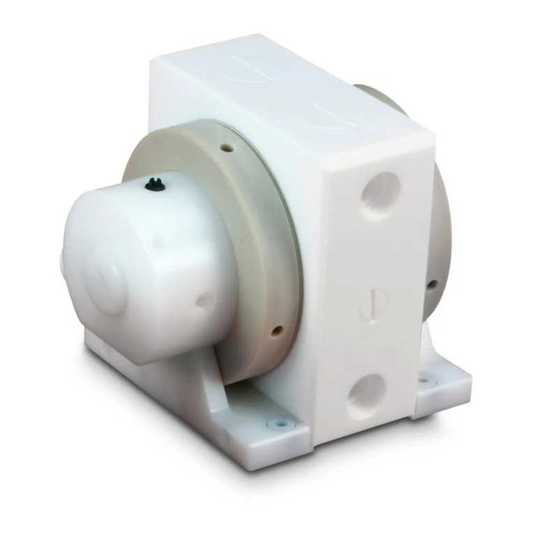
Almatec AHS Series User manual

OPERATING AND INSTALLATION INSTRUCTIONS
Heavy-Duty
Diaphragm Pumps
made of Plastic
AHS Series
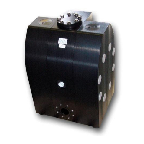
AHS 15
AHS 25
Original Instruction
Read carefully before pump installation

AHS Series · Page 2
CONTENTS
Page
1. Introduction 3
1.1. General description of the machine, appropriate use and residual dangers 3
1.2. Storage and long-term usage 3
1.3. Codesystem 4
2. Technical data 5
2.1. Performance charts 5
2.2. Dimensions 6
3. Installing the pump 7
3.1. Installation into the piping system 7
3.1.1. Product ports 7
3.1.2. Connecting the air supply 8
3.2. Start-up and operation of the pump 9
3.3. Further safety hints 9
3.4. Additional temperature hints 11
3.5. Hints for using the AHS pump with external booster for filter press feeding 11
3.5. Providing spare parts 12
4. Disassembly of the elements of construction 12
4.1. Pump housings and manifolds 12
4.2. Suction and discharge valves 13
4.3. Diaphragms 13
4.4. Center block 13
4.4.1. Shaft piston rings 13
4.4.2. Air control system PERSWING P®13
4.4.3. Air filter 14
5. Assembly of the elements of construction 14
5.1. Center block 14
5.1.1. Air control system PERSWING P® 14
5.1.2. Shaft piston rings 14
5.2. Diaphragms 14
5.3. Suction and discharge valves 14
5.4. Housing bolts with spring washers 15
5.5. Pump housings and manifolds 15
6. Testing advises 15
6.1. Air valve 15
6.2. Correct function and sealing 15
7. Troubleshooting 16
8. Spare part list 19
9. Exploded view 20
10 Optional equipment 21
10.1. External pressure booster 21
10.2. Stroke counting 21
10.3. Diaphragm monitoring 22
10.4. ANSI flange connections 22
10.5. Spare part list optional equipment 23

AHS Series · Page 3
1. INTRODUCTION
ALMATEC air-operated diaphragm pumps are constructed according to the state of the art and they are
reliable. Imminent danger by operating error or misuse can lead to damages of properties and/or persons.
The pumps are to be applied for the intended use and in a safety-related proper condition only.
Each person working on the ALMATEC diaphragm pumps concerning installation, start-up, handling or
maintenance has to read this manual completely and in an attentive way and has to follow all mentioned
procedures and safety notes.
1.1. General description of the machine, appropriate use and residual dangers
The ALMATEC AHS pumps are oscillating positive displacement pumps and are
based on the functional principle of double diaphragm pumps. The basic
configuration consists of two external pump housings with a center block between
them. Each of the pump housings contains a product chamber which is sealed
against the center block by a diaphragm. The two diaphragms are interconnected
by a piston rod. Directed by an air control system, the diaphragms are alternately
loaded with compressed air so that they move back and forth. In the first figure,
the compressed air has forced the left-hand diaphragm towards the product
chamber and displaced the liquid from that chamber through the open valve at
the top to the discharge port. Liquid is simultaneously drawn in by the right-hand
diaphragm, thus refilling the second product chamber. When the end of the stroke
is reached, it reverses automatically and the cycle is repeated in the opposite
direction. In the second figure, liquid is drawn in by the left-hand diaphragm and
displaced by the right-hand diaphragm.
The appropriate use of an Almatec air-operated double diaphragm pump of the AHS series refers to the liquid
(or sludge) transport taking into account the operation parameter mentioned in this manual and in compliance
of the given terms for commissioning, operation, assembly, disassembly and maintenance.
Even if all necessary safety measures described in this manual have been met, a residual danger exists by
leakages or mechanical damages. At sealing areas or connections liquid can be released uncontrollably then.
1.2. Storage and long-term usage
In general the ALMATEC pump is delivered operational and packaged. If the unit is not installed right away,
proper storage conditions are important for a trouble free operation later. The pump has to be protected from
wetness, coldness, dirtying, UV-radiation and mechanical influences. The following storage conditions are
recommended:
- Steady ventilated, dust and vibration free storage room
- Ambient temperature between 15°C (59°F) and 25°C (77°F) with a relative humidity below 65%
- Prevention of direct thermal influences (sun, heating)
Plastic materials are subject to aging processes depending on material, surrounding conditions and application
parameters. Chemical contact and/or increased temperature can amend material characteristics on the long
run, especially mechanical capabilities. For safety reasons, we do therefore recommend as part of every
maintenance (resp. in case of no maintenance till then after two years and then every six month): A careful
visual check of all pump parts for visible damages, a tactile check of all sealing surface (e.g. by moving a finger
along the surface after cleaning), a shape-check of the housing parts (e.g. by laying a drawer on plain surfaces)
and a movability check of all threads. Any eventually damaged part needs to be replaced!

AHS Series · Page 4
1.3. Code system
PSG Germany GmbH is certified as a modern, quality-orientated enterprise according to DIN EN ISO 9001 and
14001. Before release for dispatch, any pump has to undergo an extended final control. The performance data
registered during this are archived in our records and can be read back at any time.
As a general rule in the countries of the EU only such machines are allowed to take into operation, which are
determined to meet the regulations of the EU machinery directive, the harmonized standards, European
standards and the respective national standards. Hence the operator has to verify whether the ALMATEC pump
manufactured and delivered properly according to the customer’s order meets the mentioned requirements.
Therefore make sure, before putting the pump into operation, that the pump and the used materials of
construction are suitable for the provided application and the installation site. To check this, the exact pump
code is required. This code, the serial number and the year of construction are noted on the identification
plates on the pump itself.
Based on the ALMATEC air-operated diaphragm pump range, ALMATEC heavy-duty diaphragm pumps AHS 15
and AHS 25 have especially been developed for the requirements of abrasive media and/or high pressure
applications. The construction of the AHS pumps allows the operation with a maximum drive pressure and
discharge pressure of 15 bar.
Here is an example to illustrate the system of the ALMATEC pump codes:
AHS 25 E T T - C
Optional equipments:
B01 Air booster, 230 l/min, 1/4”
B02 Air booster, 1000 l/min, 3/8”
C Stroke counting
D Diaphragm monitoring
W ANSI flange connections
Material of E EPDM
ball valves: N NBR
T PTFE
Material of diaphragms: E EPDM
N NBR
T PTFE-EPDM compound
Material of housing: E PE UHMW
Size and port dimension
ALMATEC Heavy-duty diaphragm pump

AHS Series · Page 5
2. TECHNICAL DATA
Pump size
AHS 15
AHS 25
Dimensions mm (“): width
depth
height
266 (10.5)
177 (7.0)
336 (13.2)
336 (13.2)
256 (10.1)
412 (16.2)
Flange connections, port DIN or ANSI
Air connection BSP
15 (1/2”)
1/4"
25 (1”)
1/4"
Weight kg (lbs)
9 (20)
19 (42)
Max. particle size of solids mm (“)
4 (0.16)
5 (0.20)
Suction lift, dry mWC (‘):EPDM/NBR ball valves
PTFE ball valves
Suction lift, wet mWC (‘)
2 (6.6)
1.5 (4.9)
9.5 (31.2)
2.5 (8.2)
1.5 (4.9)
9.5 (31.2)
Max. driving and operating pressure bar (psig)
15 (218)
15 (218)
Max. operating temperature °C (°F)
70 (158)
70 (158)
Sound pressure level acc. to DIN 45635,
part 24, depending on the operating data
[dB (A)]: driving pressure 3 bar
driving pressure 5 bar
driving pressure 7 bar
68-77
68-84
68-85
76-86
78-88
79-88
2.1. Performance charts
The data refer to water (20°C/68°F), under using of a compressor Atlas Copco VSG30 and calibrated measuring
equipment. The specified performance data are warranted by ALMATEC in accordance with DIN EN ISO 9906.
The blue lines state the air consumption in Nm³/min.

AHS Series · Page 6
2.2. Dimensions

AHS Series · Page 7
* in mm, with DIN flanges
** in inch, with ANSI flanges
3. INSTALLING THE PUMP
The number in brackets, which is added to every part mentioned in the following explanations, refers to its
position in the spare part list and the exploded view. UV-radiation can damage the housing parts of pumps
made of PE. The operator is responsible for an adequately stability and an appropriate fixation of the piping
according to the state of the art. To facilitate the installation and maintenance shut off valves should be
installed right before and after the pump.
3.1. Installation into the piping system
Each of the shock absorbers [15] the pump is standing on is equipped with a female thread at its bottom for
easy installation of the pump. Before connecting the pump, the blind plugs have to be removed from the
suction and discharge manifolds [4] as well as the air inlet [21].
3.1.1. Product ports
In general, the pumps have to be connected load free. Neglecting this causes leakage and maybe even
damages. They cannot serve as a fixing point within a piping system. To avoid vibrations compensators on both
sides of the pump are recommended. Alternatively, hoses for suction and discharge help absorbing vibrations.
These would as well avoid the transfer of pulsation and noise onto pipes, tanks and other parts of a plant,
besides the conveyance is more gentle. These hoses have to carry an appropriate armourment to avoid
diminishing the diameter of the suction pipe by the vacuum the pump develops.
The nominal width of the connection pipes has to be chosen in accordance to the connections of the pump.
A smaller piping can cause cavitation (suction line) as well as a loss of performance (suction and discharge line).
In case the pipe is too big, the dry suction capacity of the pump can decrease. Using flanges according to DIN
DN 15/25 PN 16 or ANSI 300 lb/sq.inch, the suction line has to be connected to the lower manifold [4], the
discharge to the upper one. The position of the manifolds can be varied in steps of 90° for a horizontal or
vertical connection. To do so, the corresponding two housing bolts [14] have to be taken out beforehand. After
turning the manifold [4], the bolts have to be fixed and tightened again.
The first version is the standard configuration when the pump is shipped: Suction port horizontal and discharge
port vertical to the top.
Seal the suction line diligently to avoid air intrusion. A suction line continuously rising will prevent the formation
of air locks in the line which would affect the suction lift.
mm* A B C D E F G H I K L M N O P Q R S T U V
AHS 15 266 152 336 316 20 37 DN15/PN16 65 M12 190 230 112 R 1/4" 263 53 150 177 520 40 M8
AHS 25 335 200 412 392 20 44 DN25/PN16 85 M12 250 290 160 R 1/4" 336 56 190 255 748 40 M8
inch** A B C D E F G H I K L M N O P Q R S T U V
AHS 15 10.5 6.0 13.2 12.4 0.8 1.5 ANSI 1/2" - 300lbs 2.6 1/2" UNC 7.5 9.1 4.4 BSP 1/4" 10.4 2.1 5.9 7.0 0.2 0.8 1.6 M8
AHS 25 13.2 7.9 16.2 15.4 0.8 1.7 ANSI 1" - 300lbs 3.5 5/8" UNC 9.8 11.4 6.3 BSP 1/4" 13.2 2.2 7.5 10.0 0.3 1.9 1.6 M8

AHS Series · Page 8
If pressurised air chambers are positioned beyond the pump discharge, these have to be disconnected from
the pump by non-return valves. If using the pump for filter press feeding the ALMATEC heavy-duty diaphragm
pump regulates itself automatically according to the pressure of the filter press, additionally influencing the
pump by a pressurised regulated air chamber cannot be permitted on principle.
3.1.2. Connecting the air supply
The air inlet [21] is located in the middle of the center block [18]. When delivered it is covered by a bilingual
sticker with safety instructions, which can be easily removed. To supply the pump with driving air sufficiently,
an appropriate diameter of the air supply line is required, at least the same nominal size as the air inlet of the
pump (AHS 15/25). We recommend connecting the pump via a hosepipe with adapter and sealing. If this is not
available, a direct connection via pipe thread and sparingly attaching some sealing tape is possible. Please note:
The air inlet [21] is made of plastic to protect the center block [18], seal in carefully. Take care that no dirt or
particles can intrude into the pump during the connection, as these can accumulate inside the pump and can
cause malfunctions. An air filter [22] directly behind the air inlet [21] prevents the entry of bulk particles.
The following regulators should be included in the air supply line (especially if the pump is used for filter press
feeding):
•Pressure regulator with maintenance unit/separator for condensed water (no oil supply)
The pressure regulator is used to adjust the final pressure the press will stop at. Please note: The
time required for pressing increases along with the pressure. A higher pressure means a more dry
filter cake and higher stress for all materials involved. A general guiding value cannot be given, the
correct pressure has to be found out for every single application.
•Air throttle (e.g. needle valve)
This is helpful to limit the flow rate when starting to fill the press (without limiting the velocity,
the pump will start very fast which results in a lower quality of the filter cake and increased wear
of the pump). At the choice of the valve a sufficient pass-through capacity of the valve as well as
an easy fine tuning has to be taken care of.
Besides, the following elements can be installed in the air supply line:
•Solenoid valve: depending on the automatization; optimally installed before the pressure
regulator, as mostly regulated.
•Micro filter: protects the pump from remains of dirt and oil in the compressed air. A micro filter
can replace an air maintenance unit.
•Pressure relief valve: prevents irregular regulation of the pump and filter press.
The integrated air control system PERSWING P® is a precision-control that requires oil-free, dry and clean
compressed air for optimal function. The quality of the driving air for the pump depends on the operating
conditions (e.g. flow rate at the beginning, final pressure of the filter press). For a rough orientation, we
recommend to lean against the following quality classes of ISO-DIS-8573-1: solids - class 2, dew point –class 2-
3, oil - class 3. . A muffler [20] soiled after short period of operation indicates soiled driving air which can be
helped by a micro filter chosen according to the max. air flow. The expansion of pressurized air inside the pump
causes a major temperature drop. Eventual icing of the muffler or the whole pump most often results from
insufficiently dried driving air in humid surroundings, icing from the outside may occur despite the driving air
is dried. If so, a prolonged waste-air-exhaust (ca. 500 mm / 20 inch by pipe or hose) to give room for expansion
can be helpful. In applications with a tendency to freezing at the waste air exhaust, good experiences in practice
have been achieved by pre-heating the driving air to increase the distance to the dew point of the air. Doing
so, it has to be considered that the driving air temperature generally may not exceed 50°C (122°F) to avoid
expansion and sticking effects on the air side. This max. air temperature is a well valid when using a compressor
producing warm air which is e.g. often true for truck compressors. When installing the pump into boards or
cabinets, it has to be ensured that cold air does not get caught behind the muffler. ALMATEC heavy duty pumps
do not require any lubrication. It has to be secured, that no oil can enter the pump.

AHS Series · Page 9
3.2. Start-up and operation of the pump
When starting to install the pump, the housing bolts [14] have to be tightened. This has to be done before the
pump develops a decent discharge pressure. The bolts [14] should be tightened crosswise and alternately
starting with those arranged in the circle of the diaphragm. The aim of this is to work against the effect of
housing parts "settling" after manufacture (e.g. during transport) because of varying temperatures.
The housing bolts [14] have to be fixed according to the torque data of the following schedule. At the beginning,
the bolts need to be checked regularly and fixed if necessary. It can also be necessary after longer periods of
stoppage, at extreme temperature variations, after transport and dismantling the pump. In case of
temperature varying between extremes or high temperature difference between the liquid and the
surrounding, the housing bolts should be controlled more frequently (interval proposals are available on
request). Once the pump is leaking because of insufficient tension of the bolts, it cannot be sealed completely
by just tightening the bolts without cleaning the surfaces. The pump has to be opened and the sealing surfaces
have to be cleaned carefully. Especially the round sealing groove in the pump housing [1] needs to be cleaned
diligently.
Size
AHS 15
AHS 25
Torque values for housing bolts Nm (ft lbs):
8 (5.9)
13 (9.6)
The pressure of the driving air should be limited to the amount required to meet the performance needed.
Excessive pressure increases both the air consumption and the wear of the pump. The pump is regulated by
tuning the flow rate of the air. For a proper operation at the lower performance range the regulation via a
needle valve is recommended. An empty pump has to be driven slowly (e.g. via a needle-valve). The pump
starts automatically. Pumps of the AH series are self-priming when dry, thus it is not necessary to fill the suction
line of the pump. The suction lift capacity of a liquid-filled pump, however, is much higher. The pump is
appropriate for running dry during slow operation. Dry running at high stroke frequency causes premature
wear. The pumps can briefly (up to max. one hour) be operated against a closed discharge line. Throttling on
the suction side may damage the pump. When the pump operation has been stopped by a closed discharge,
the pressure equilibrium of the diaphragms must be ensured. This can be achieved by keeping the pump
connected to the air supply pressure; for longer stoppage, the pump must be released from the pressure within
the system on both fluid side and air supply side.
Due to the material choice and thickness ALMATEC heavy-duty diaphragm pumps are particularly suitable for
abrasive media. Moreover the feeding of filter presses is a possible application field. The ideal combinative
effect of ALMATEC AHS pumps and filter presses is illustrated very well by the automatic adaptation to pressure
and flow rate. When beginning to fill the empty press, the low discharge pressure results in a high flow velocity
for fast filling. Because of the pressure of the press increasing along with the amount of sludge inside, the flow
rate of the pump automatically reduces until standstill at final pressure without any regulating or additional
security devices. In contrast to a mechanically driven diaphragm pump, the ALMATEC pump stops itself without
any further air consumption. This "integrated" automatic regulation permits operating the pump within its
capacity without any danger of over-pressure.
3.3. Further safety hints
•Installation, operation, and maintenance by qualified staff only.
•Before start-up of the pump anyone should acquaint oneself with the explanations of the chapter
troubleshooting (see pages 17-19). Only by this the defect quickly can be realized and eliminated in
case of trouble. Problems which cannot be solved or with an unknown reason should be passed on to
the manufacturer.
•Before any maintenance and service procedures arising on the pump or on the optional equipment,
the complete installation has to be turned off and protected against accidental turn on. This is
possible by a lockable emergency stop for the air supply of the pump. Additional a danger sign
against restart should be attached.

AHS Series · Page 10
•Pressure tests of the plant a pump is included in may only be carried out with the pump disconnected
from the pressure on both ports or by using the pressure the pump develops while operating. The
load of a pressure in the plant may damage the pump.
•AODD pumps must not be operated with a positive suction pressure.
•Depending on the conditions of operation, the liquid conveyed might escape from the pump through
the muffler in case of a diaphragm rupture (in this case muffler has to be replaced). For further safety
requirements the optional equipment diaphragm monitoring and barrier chamber system are
recommended.
•In case of a diaphragm rupture, it might be possible for the fluid pumped to intrude into the air side
of the pump. In very adverse conditions - e.g. pressure within the fluid system during stopped air
supply - the fluid might as well find its way into the air supply lines. To protect other devices like
pneumatic valves, it is recommended to protect the air supply line accordingly, e.g. via a non-return
valve. This would as well avoid polluting the air supply line.
•The state of the muffler has to be inspected regularly, as a blocked muffler can be forced out of the
pump. If this happens, damages of properties and/or persons cannot be excluded.
•Pumps of the AH-Series must not be submerged.
•When blowing out the filter press, the pump has to be protected against the pressure by a valve or a
slide.
•If the product tends to settle, the pump has to be flushed regularly. For larger solids a filter has to be
installed in the suction line.
•In case of delivery of hot liquids the wetted pump must not standstill for a longer time, because it
could lead to temporary leaks in the valve area and to a blockade of the air control system.
•The relevant effective security advises have to be respected.
•Pools of liquid which appear in the near outer area of the pump have to be inspected on danger
potential, if necessary safety measures are to be taken.
•Chemical and biological reactions in the product chamber of the pump (mixture of different
substances) and the freezing of the liquid have to be avoided.
•Before starting to disassemble the pump, take care that the pump has been emptied and rinsed.
Both ports piping are to be closed and drained if applicable. Further the pump has to be cut off from
any energy on the air and product side. If the pump is being deported from the plant, a reference
about the delivered liquid has to be attached.
•Please respect the relevant additional security advices, if the pump has been used for aggressive,
dangerous or toxic liquids (e.g. suitable protective equipment according to the safety data sheet of
the liquid). In case of a diaphragm rupture, it is possible that residues of the liquid remain behind the
diaphragms, in the area of the air control system and at the muffler, despite of several flushing
processes. Hence, appropriate safety equipment according to the safety data sheet of the liquid is
indispensable.
•Additional advice for handling sensitive Fluids: With correct material choice, all wetted parts inside
the pump are made from materials appropriate for your fluid - selected types as well for for food
contact. A malfunction, however, might result in a contact of the fluid to components that are non-
wetted during normal operation (e.g. inside the air section). Therefore, we recommend as usual for
pumps, to discard the batch after a malfunction when handling sensitive fluids. Please consider that a
conformity for food-contact solely refers to wetted materials themselves, NOT to a “Hygienic Pump
Construction”
•Before putting the pump back into operation, the tightness of the pump has to be checked.
•Air-operated diaphragm pumps can lead to bruises when lifting, sinking or assembling them.
Appropriate accessories and safety equipments are to be used. Big and heavy modules have to fixed
and secured to lifting gears when transporting/replacing them.
•Especially when deliver critical liquids, wear parts, like diaphragms, should be replaced within a
preventive maintenance.
•The use of non-original ALMATEC spare parts and structural changes lead to the lapse of the
warranty immediately. When operating such a pump, damages of properties and/or persons cannot
be excluded.
•The operation of the pump with nitrogen as driving gas is possible. In closed rooms sufficient
ventilation must be provided.
•Possible electrical connections (e.g. when using optional equipment with controllers) may be
executed by a qualified person only. The regulations of the respective manufacturers are to be
followed.
•At any work arising it has to be made sure that no explosive atmosphere can appear. Appropriate
safety equipment is recommended.
AHS Series · Page 11
•The pump is tested with water before shipment. Water residues inside the pump cannot be
precluded. If the liquid, which is wanted to be conveyed, potentially interacts with water, please
consult Almatec.
•Procedure for pump return: According to the requirements of our 14001-certification, every unit
which is send to ALMATEC for diagnosis or maintenance reasons has to be accompanied by a filled
out decontamination-sheet. Otherwise a processing is not possible. The decontamination-sheet is
enclosed to this manual. Please pay attention to the further safety regulations.
3.4. Additional temperature hints
The temperature and pressure limitations listed on page 5 are solely based on mechanical temperature limits
of the housing material used. Depending on the fluid pumped, the maximum safe operating temperature of
the housing material can be reduced significantly.
A general aspect of lower temperatures is, that below 0°C (32°F) cold-brittling of the elastomers used within
the pumps can results in accelerated wear. Regarding the housing materials, please note that PE - other than
PP - keeps its mechanical strengths at low temperatures. ALMATEC pumps can therefore be operated safely as
well within low-temperature installations: However, with liquids below 0°C (32°F) accelerated wear of internal
parts has to be accepted. Moreover, freezing, bogging or crystallisation of the fluid pumped must be avoided,
especially within the pump.
Please consider, that viscosity and specific gravity of most fluids change with temperature (most often
increasing at lower temperature). Depending on the application, this fact may not only result in result in a
reduced flow rate, the pump may even be unable to prime the thicker and/or “heavier“ fluid any more.
In case of varying application temperatures, the housing bolt tension has to be controlled very thoroughly, as
variations like these can change the effective tension of the housing bolts via the different thermal expansion
characteristics of single.
3.5. Hints for using the AHS pump with external pressure booster for filter press feeding
Pumps of the AHS series are approved for a maximum drive pressure of 15 bar (218psig). If an external pressure
booster is used for achieving this high pressure for filter press feeding please consider the following:
•By continual operation of an air pressure booster is has to be considered that the amplifier is subject
to wear and consumes air.
•If such a continuous operation is planned, the nominal output may lead to a bottleneck for the
operation of the pump, that the pump does not reach its maximum capacity. In this case the filling of
the widely empty filter press is significantly slowed.
Therefore we recommend the following operation:
•Start the filling of the filter press by-passing the booster with normal driving pressure of e.g. 7 bar
(100 psig). The pump can quickly work and the press will be prefilled.
•Once the pressure in the press corresponds to the air pressure, the pump stops automatically
without any damage.
•By starting the air supply through the booster after the filter press is already prefilled, the load of the
booster and pump will be limited. Primarily, due to the now slow working pump a smaller booster
can be used than it would be the case by continuous use of the booster.
•To avoid the manual intervention of switching the air supply path, we recommend connecting a
pressure sensor with appropriate interconnection in the system control.
Additional remarks:
•AHS pumps coming with special equipment code BO1 or BO2 (external booster) have a direct air
connection between pump and booster. This can limit the capacity of the pump.
•In case of a diaphragm rupture liquid may find its way into the air area and also into the booster and
possibly leads to contaminations or damages.

AHS Series · Page 12
3.6. Providing spare parts
We recommend having spare part kits S on stock. These include the relevant spare parts for your pump. Only
use original ALMATEC spare parts for repairs and / or preventive maintenance work. If this is not observed,
the CE and ATEX markings, the declaration of conformity (s) and the guarantee claim for the pump will expire.
All work on the pump may only be carried out with the appropriate tools and by trained specialist personnel.
4. DISASSEMBLY OF THE ELEMENTS OF CONSTRUCTIONS
When dismantling a pump the mentioned procedures and safety notes on the pages 8-12 have to be considered
generally.
ALMATEC AHS pumps are often used to transport sludge, so that deposits and incrustations inside the pump
can complicate the disassembly. It has been proved to be useful to soak the components before dismantling in
water (if compatible with rinsing agent) to facilitate the separation after a certain waiting period.
The general design of the ALMATEC AHS pumps is simple. Every pump comes along with a mounting tool for
the air-valve system [25]. Take out the muffler [23] installed onto the center block [18] before dismantling the
pump to protect it against damages during the disassembly.
Required tools
AHS 15
AHS 25
Item
Description
Tool
Tool size
Tool size
10
Lock pin, discharge valve
Screwdriver
Please check yourself
13
Plug
Open-end spanner
30 mm
36 mm
14
Housing bolt
Open-end
spanner/ring
wrench/socket
wrench
10 mm
13 mm
21
Air inlet
Open-end spanner
19 mm
27 mm
25
PERSWING P® air control system
ALMATEC Tool
+ ring wrench
1 15 901 54
24 mm
4.1. Pump housings and manifolds
At first, loosen those bolts [14] at the top and at the bottom using a wrench and take them out together with
the tension plates [3]. After that, unscrew the remaining housing bolts [14], remove the tension discs [2] and
draw the housing bolts [14] out to the left until they are left of the right hand side diaphragm [16]. Now, the
right pump housing [1] can be taken away (if necessary carefully help it move with a rubber hammer). Draw
out both manifolds [4] and remove the O-rings [5,6].
Image 1 Image 2

AHS Series · Page 13
4.2. Suction and discharge valves
Lay down the pump housing [1] on its outer surface. Loosen lock pin discharge valve [10] and remove. Turn the
discharge valve [9] along its longitudinal axis by 180° using a suitable round bar (Image 1). After ca. 70° change
the bar to the other side of the discharge valve [9] (Image 2) and keep on turning the remaining 110°. Take care
not to damage the sealing surface for the diaphragm (V-groove) during this. Draw the discharge valve [9]
downwards and take it out (Image 3). Withdraw O-Ring, valve [11]. The discharge valve ball [17] can be taken
out easily now. The valve stop [12] can be shoved downwards to take it out (Image 4).
Image 3 Image 4
Unscrew the plug [13] out of the pump housing [1]. Use a suitable round bar to press out the suction valve [7]
from outside to inwards through the bore of the plug [13]. Take this as well as the suction valve ball [17] and
the valve seat [8] out. Draw of O-ring, valves [11].
4.3. Diaphragms
Screw one diaphragm [16] counterclockwise off the shaft [19]. Pull the other diaphragm [16] together with the
shaft [19] out of the center block [18]. Screw the set screws shaft [24] of the diaphragms [16].
4.4. Center block
Lay the center block [19] plainly onto a soft base (do not damage the sealing edges!).
4.4.1. Shaft piston rings
Remove shaft piston rings [20] from their grooves carefully (do not damage the edges in the center housing) A
re-assembly of the same piston rings is impossible; they have to be replaced. Remove O-rings [20] from the
groove.
4.4.2. Air control system PERSWING P®
Screw off both end caps of the PERSWING P® air control system [25] using the plastic mounting tool delivered
with the pump. Take out main and pilot piston. Press out the air-valve housing with the mounting tool turned
around.

AHS Series · Page 14
4.4.3. Air filter
To take out the air filter [22] the air inlet [21] has to be screwed off first, afterwards the filter [22] can be
unscrewed easily with a big screw driver.
5. ASSEMBLY OF THE ELEMENTS OF CONSTRUCTION
5.1. Center block
5.1.1. Air control system PERSWING P®
To install the air control system PERSWING P® [25], first screw in one end cap flushly into the center block [18].
Insert one of the six O-rings, air-valve housing [26] into the end cap from the inside. Moisten the four O-rings
[26] of the air-valve housing with a bit of water and push the housing into the center block [18] using the
mounting tool. Take care that it slips in softly. Do never insert the housing violently with a hammer. In case the
housing cocks or hardly gets in, take it out again completely and start again. Insert the main piston and the
pilot piston. Lay the sixth O-Ring [26] on the edge of the air-valve housing and screw in the second end cap.
5.1.2. Shaft piston rings
The O-Rings located underneath the piston rings [20] have to be installed first. A
re-assembly of the used piston rings is impossible; they have to be replaced! To
assemble piston rings [20], carefully shape them like kidneys with locking ring
pliers and insert the rings into the grooves; completely press the rings into the
grooves smoothly using a clean housing bolt [13]. Insert the shaft bushing, long
[39] on side of the center block were the big O-ring dual stage bushing [38] is
located.
5.2. Diaphragms
Screw in set screws, shaft [24] into the diaphragms [16] and tighten them. Fix one diaphragm [16] with set
screw [24] onto into the shaft [19], shove it into the center block [18] and fix the position with the housing
bolts [13]. Fit the second diaphragm to the other end of the shaft and push the housing bolts [13] carefully (if
necessary, rotate the bolt smoothly while pushing) through the bore holes of the diaphragm without damaging
the diaphragm and its surfaces. The sealing surfaces of the diaphragms [16] and the pump housings [1] have
to be absolutely clean and undamaged; mere small scratches can cause leaking.
5.3. Suction and discharge valves
The inner parts of the pump housings [1] have to be re-assembled exactly vice versa to the way described for
the disassembly. Ensure that the suction [7] and discharge valves [9] are pushed into their extreme position
and that the bores in the pump housings [1] (at the bottom of the liquid camber) and the suction valves [7] fit
to each other. Make sure that the hole in the pump housing [1] and the thread of the locking pin discharge
valve [10] are aligned, then install locking pin discharge valve [10] in the discharge valve [9] and screw it.

AHS Series · Page 15
5.4. Housing bolts with spring washers
When assembly the housing bolts [14] pay attention to the correct arrangement of
the spring washers. The pump sizes AHS 15 / AHS 25 have three spring washers on
both housing bolt sides. The arrangement represented in the drawings makes an
improvement of power and way possible. Already used spring washers may not be
installed again.
5.5. Pump housings and manifolds
All the sealing elements [5,6] of the manifolds [4] should always be replaced, moisturizing the rings helps to
ease the assembly. Draw the inner O-ring [6] onto the manifold [4] and press the outer O-ring [5] into the pump
housing [1]. Set the manifolds [4] on the plainly lying pump housing [1] slightly rotating them. Put the central
unit mounted before [center block, diaphragms, housing bolts] and the pump housing [1] lying on its side with
the manifolds [4] standing upwards together.
Mount the second pump housing [1]. Now, both the upper and lower pair of housing bolts [14] can be inserted.
Make sure that the position of the manifolds [4] matches the installation situation, to avoid later readjustment.
Install tension discs [2] and tension plates [3]. Attach nuts and washers to the ends of the bolts and fix the
housing bolts [14] crosswise evenly according to the given torque values until the pump housings [1] are
situated on the center block [18]. Any further tightening of the bolts does not improve sealing but can deform
the housing!
Finally screw the muffler [23] into the center block [18]. The pump can be operated now.
6. TESTING ADVISES
6.1. Air control system
The correct function of the air distribution can easily be checked for an assembled center unit consisting of a
center block [18] completely equipped with all inner parts. Attach the air supply. Move the pilot piston back
and forth while the bores where the air leaves the center block [18] are blocked. Now, the switching and the
movement of the main piston have to be audible.
6.2. Correct function and sealing
The fully assembled ALMATEC AHS pump has to be equipped with an air supply as well as temporary suction
and discharge lines both leading to a water containment. The dry suction capacity can be checked with a
vacuum gauge by closing the suction line carefully complete. Slowly closing the discharge has to cause standstill
of the pump. The pressure in the discharge line has to correspond to the air pressure. The pump switches to
the other product chamber by scarcely opening the discharge for a short time. No liquid may escape from the
pump in both positions. After finishing the test, the air supply has to be closed at first, after that the discharge
line has to be opened slowly to let the pump empty itself while the suction line is opened.

AHS Series · Page 16
7. TROUBLESHOOTING
Malfunction
Possible Reason
Solutions/Remarks
pump does not operate
air supply line blocked/closed
muffler blocked
working chambers blocked
air control system defective
discharge line blocked/closed
open air supply
clean/replace muffler
remove blockage
replace air valve system
clean/open line
pump operates unsteadily
piston rings worn
air control system worn
diaphragm rupture
air control system soiled
check valve blocked
icing
replace piston rings
replace air control system
replace diaphragm, clean pump
clean/replace air control system
cleaning, removal of bulk particles
improve air processing
air within liquid
suction line leaky
container with liquid empty
diaphragm rupture
cavitation
seal suction line
fill/new container
replace diaphragm
adapt suction lift, possibly install
suction pressurised air chamber
insufficient discharge pressure
insufficient pressure/amount of
driving air
air supply line leaky
air control system leaky
check valve worn
more air consuming components
Operating with booster:
booster not connected
booster defective/worn
booster small dimensioned
increase air supply
check/repair air supply
replace air control system
check/replace check valve
increase pressure/amount of air
connect booster
repair booster
use other booster
output decreases
air control system soiled
icing
air pressure drop
suction line/inlet strainer soiled
discharge line/outlet strainer soiled
muffler blocked
check valve worn
change in viscosity
more air consuming components
Operating with booster:
booster defective/worn
clean/replace air control system
improve air processing: dryer/filter
ensure sufficient supply of air
cleaning
cleaning
replace the muffler
replace valve
change back/adjust pump
increase pressure/amount of air
repair booster

AHS Series · Page 17
Malfunction
Possible Reason
Solutions/Remarks
pump stops itself
icing of the air control system
air pressure to low
air pressure drop
discharge line blocked
air filter blocked
valve closed
air control system defective
wear/leaking of air control system
diaphragm rupture
check valve blocked/worn
Operating with booster:
booster defective/worn
booster small dimensioned
improve air processing:
dryer/heater etc.
increase air pressure
ensure sufficient air supply
clean discharge line
clean air filter
open valve
replace air control system
replace diaphragm, clean pump
clean/replace check valve
repair booster
use other booster
pumps operates, however suction
capacity insufficient
pump operates too fast
operation beyond physical limits
cavitation
operation beyond pump capacity
air cushion within
suction/discharge line
dry suction against discharge
pressure
valve filter within suction line
closed
valve filter within discharge line
closed
container with liquid empty
vacuum inside the container
wear of the check valves
suction line leaky
suction line blocked
air pressure cushion at discharge
check valve blocked
start more slowly
adjust installation
check, cool down
adjust installation resp. install
bigger pump
bleed the line
wet pump, start without pressure
open valve/clean filter
fill/new container
bleed container
replace valves
seal suction line
clean suction line
bleed discharge line
clean/replace valve
insufficient suction capacity after
pump repair
pump with booster does not work
after repair
connections tighten incompletely
check valves inserted falsely
booster clogged/damaged
tighten/seal connections
correct positioning of check valves
clean/repair booster
diaphragm overstrained
pressure within the plant/system
inadmissible vacuum
icing
ensure that pressure is only
developed by the pump itself,
check plant/valves,
replace diaphragms
check suction line, open valve
improve air processing
leaking between housing parts
housing bolts loosened
O-rings sleeve damaged
diaphragms attacked chemically
diaphragms overstrained
tension installation/pipework
tighten bolts, check pump
replace O-rings
replace diaphragms
replace diaphragms
loosen, eliminate tension,
use of a compensator

AHS Series · Page 18
Malfunction
Possible Reason
Solutions/Remarks
muffler grey
driving air too humid, icing
improve quality of driving air
muffler black
soiled, oily air
improve quality of driving air,
install sensitive filter in suction line
pump is connected to air but does
not operate
air control system blocked
bulk particles/dirt
chemical influence (O-rings
swollen)
valve closed in discharge line
Operating with booster:
booster defective/worn
clean/replace air control system
clean pump, replace necessary
parts, improve air quality
check, replace damaged parts
open valve
repair booster
liquid leaves the pump via the
muffler
diaphragm rupture
replace diaphragms,
clean pump

AHS Series · Page 19
8. SPARE PART LIST
Pump sizes
AHS 15
AHS 25
Item
Pc.
Description
Material
Part number
Part number
1
2
Pump housing
PE
3 15 510 52
3 25 510 52
2
2
Tension disc
1.4301
3 15 508 22
3 25 508 22
3
4
Tension plate
1.4301
3 15 608 22
3 25 608 22
4
2
Suction/discharge port
PE
3 15 611 52 - FD
3 25 611 52 - FD
5
4
O-Ring, ports, outside
EPDM
9 37 528 72
9 42 540 72
6
4
O-Ring, ports, inside (code EEE/ENN)
EPDM
9 33 526 72
9 33 526 72
O-Ring, ports, inside (code ETT)
FEP/FKM
9 33 553 59
9 33 553 59
7
2
Suction valve
PE
3 15 013 52
3 25 013 52
8
2
Suction valve seat
PE
3 15 014 52
3 25 014 52
9
2
Discharge valve
PE
3 15 515 52
3 25 515 52
10
2
Lock pin, discharge valve
PETP
3 15 519 84
3 15 519 84
11
4
O-ring, valves (code EEE/ENN)
EPDM
9 37 603 72
9 48 604 72
O-ring, valves (code ETT)
PTFE
9 37 603 60
9 48 604 60
12
2
Ball retainer
PE
3 15 016 52
3 25 016 52
13
2
Plug
PE
1 25 017 52
3 25 017 52
14
12
Housing bolt
1.4301
3 15 620 22
3 25 620 22
15
4
Shock absorbers
NR
1 15 322 85
1 15 322 85
16
2
Heavy duty diaphragm (code EEE)
EPDM
3 15 031 72
3 25 031 72
Heavy duty diaphragm (code ENN)
NBR
3 15 031 71
3 25 031 71
Heavy duty diaphragm (code ETT)
PTFE
3 15 031 67
3 25 031 67
17
4
Valve ball (code EEE)
EPDM
1 25 032 72
3 25 032 72
Valve ball (code ENN)
NBR
1 25 032 71
3 25 032 71
Valve ball (code ETT)
PTFE
1 25 032 60
3 25 032 60
18
1
Center block
PA
3 15 740 53
3 25 740 53
19
1
Shaft
1.4301
3 15 630 22
3 25 630 22
20
3
Shaft piston ring, cpl.
PTFE
1 15 041 64
1 40 041 64
21
1
Air inlet
PETP
1 15 047 84
1 40 047 84
22
1
Air filter
PE
1 15 043 51
1 40 043 51
23
1
Muffler
PE
1 15 244 51
1 40 244 51
24
2
Set screw, shaft
1.4305
9 10 220 22
9 12 221 22
25
1
PERSWING P® air control system, cpl.
PETP
3 15 601 84
3 25 601 84
26*
6
O-ring, air valve housing
NBR
9 35 504 71
9 46 515 71
* included in item 25
All parts in italics are not product wetted.
Please see page 4 for explanation of the pump code.
When ordering please state the serial number of the pump.
For spare part lists for special equipment please see page 22 and the following ones.

AHS Series · Page 20
9. EXPLODED VIEW
This manual suits for next models
3
Table of contents
Other Almatec Water Pump manuals

Almatec
Almatec BIOCOR Series User manual

Almatec
Almatec FUTUR Series User manual

Almatec
Almatec E 08 User manual

Almatec
Almatec CXM Series User manual

Almatec
Almatec A Series User manual

Almatec
Almatec E 10 User manual

Almatec
Almatec BIOCOR Series User manual

Almatec
Almatec AHD Series Operation instructions

Almatec
Almatec E Series User manual

Almatec
Almatec Quattroflow 1200SU User manual