Product ports
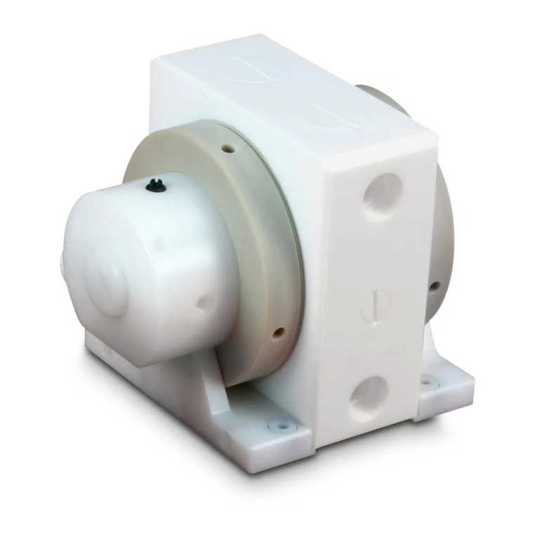
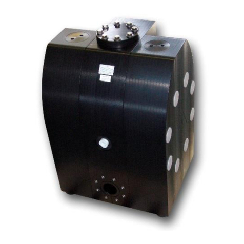
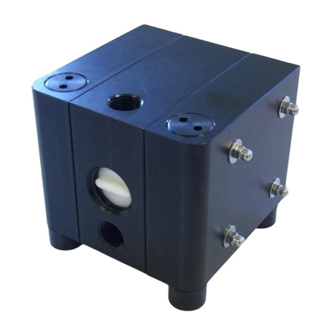
The product ports are integrated into the center housing [2]. Different port configurations can be obtained. The
standard configuration of the A-Series at delivery is with the suction inlet horizontally at the bottom and the
discharge outlet horizontally at the top (figure 4.1). Further possible configurations:
• Suction inlet vertically at the bottom, the discharge outlet horizontally at the top (figure 4.2)
To obtain this configuration, the plug of the center housing [8] has to be removed and set in the
standard inlet.
• Suction inlet horizontally at the bottom, the discharge outlet vertically at the top (figure 4.3)
Unscrew the housing bolts [15], take off the side housings [1] and turn the center housing [2]. Remount
the pump and adjust the plug [8] accordingly.
figure. 4.3figure. 4.1 figure. 4.2
Installation and operation
UV-radiation can damage the housing parts of pumps made of PE (material code E). In general, the pump has
to be connected load free. Neglecting this causes leakage and maybe even damages. To avoid vibrations,
pulsation dampers and compensators are recommended. Before connecting the pump, take the yellow blind
plugs out of the suction and discharge connections as well as the air inlet [19] in the center housing [2]. The
connections of ALMATEC pneumatic diaphragm pumps in polymer materials have slightly tapered threads.
Use threadseal only sparingly, otherwise the connections could be damaged.
To facilitate the installation and maintenance shut off valves should be installed right before and after the
pump. The nominal width of the connection pipes has to be chosen in accordance to the connections of the
pump. A smaller piping can cause cavitation (suction line) as well as a loss of performance (suction and
discharge line). In case the pipe is too big, the dry suction capacity of the pump can decrease. Connect the
suction line to the lower connection in the center housing [2]. Seal the suction line diligently; hosepipes should
be suitably armoured. A suction line continuously rising will prevent the formation of air locks in the line which
would affect the suction lift.
The air inlet [19] is located in the middle of the center housing [2]. Before installation make sure that the air
supply pipe is free of solids. To supply the pump with driving air sufficiently, the pipe diameter should match
the size of the air inlet. Take care that no dirt or particles can intrude into the pump during the connection, as
these can accumulate inside the pump and can cause malfunctions. An air filter [20] directly behind the air inlet
[19] (not included in A 08 and A 10) prevents the entry of bulk particles.
The integrated air control system PERSWING P®is a precision-control that requires oil-free, dry and clean
compressed air for optimal function. If humidity is expected, a water separator or air dryer has to be fitted to
protect the pump from blocking by ice. The ideal condition is the dewpoint of air at -20°C. In humid
surroundings, icing from the outside may occur despite the driving air is dried. If so, a prolonged waste-air-
exhaust (ca. 500 mm by pipe or hose) can be helpful. When installing the pump into boards or cabinets, it has
to be ensured that cold air does not get caught behind the muffler.
The pressure of the driving air should be limited to the amount required to meet the performance needed.
Excessive pressure increases both the air consumption and the wear of the pump. The pump is regulated by
tuning the flow rate of the air. An empty pump has to be driven slowly (e.g. via a needle-valve). The pump
starts automatically. Pumps of the A-Series are self-priming when dry, thus it is not necessary to fill the suction
line of the pump. The suction lift capacity of a liquid-filled pump, however, is much higher. The pump is
appropriate for running dry during slow operation. Dry running at high stroke frequency causes premature
wear.The maximum permissible stroke frequencies can be found in the following table. The pumps can briefly
(up to max. one hour) be operated against a closed discharge line. Throttling on the suction side may damage
the pump.
4
