9
Pools of liquid which appear in the near outer area of the pump have to be inspected on
danger potential, if necessary safety measures are to be taken.
Chemical and biological reactions in the product chamber of the pump (mixture of different
substances) and the freezing of the liquid have to be avoided.
Before starting to disassemble the pump, take care that the pump has been emptied and
rinsed. Both ports piping are to be closed and drained if applicable. Further the pump has
to be cut off from any energy on the air and product side. If the pump is being deported
from the plant, a reference about the delivered liquid has to be attached.
Please respect the relevant additional security advices, if the pump has been used for
aggressive, dangerous or toxic liquids (e.g. suitable protective equipment according to the
safety data sheet of the liquid). In case of a diaphragm rupture, it is possible that residues
of the liquid remain behind the diaphragms, in the area of the air control system and at the
muffler, despite of several flushing processes. Hence, appropriate safety equipment
according to the safety data sheet of the liquid is indispensable.
Before putting the pump back into operation, the tightness of the pump has to be checked.
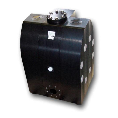
Pumps of the BIOCOR series must not be submerged.
Air-operated diaphragm pumps can lead to bruises when lifting, sinking or assembling
them. Appropriate accessories and safety equipments are to be used. Big and heavy
modules have to fixed and secured to lifting gears when transporting/replacing them.
Especially when deliver critical liquids, wear parts, like diaphragms, should be replaced
within a preventive maintenance.
The use of non-original ALMATEC spare parts and structural changes lead to the lapse of
the warranty immediately. When operating such a pump, damages of properties and/or
persons cannot be excluded.
The operation of the pump with nitrogen as driving gas is possible. In closed rooms
sufficient ventilation must be provided.
Possible electrical connections (e.g. when using optional equipment with controllers) may
be executed by a qualified person only. The regulations of the respective manufacturers
are to be followed.
At any work arising it has to be made sure that no explosive atmosphere can appear.
Appropriate safety equipment is recommended.
Procedure for pump return: According to the requirements of our 14001-certification, every
unit which is send to ALMATEC for diagnosis or maintenance reasons has to be
accompanied by a filled out decontamination-sheet. Otherwise a processing is not
possible. The decontamination-sheet is enclosed to this manual. Please pay attention to
the further safety regulations.
Additional temperature hints
The temperature and pressure limitations listed on page 5 are solely based on mechanical temperature
limits of the housing material used. Depending on the fluid pumped, the maximum safe operating
temperature of the housing material can be reduced significantly.
A general aspect of lower temperatures is, that below 0°C cold-brittling of the elastomers used within the
pumps can results in accelerated wear. ALMATEC pumps can therefore be operated safely as well within
low-temperature installations: However, with liquids below 0°C accelerated wear of internal parts has to be
accepted. Moreover, freezing, bogging or crystallisation of the fluid pumped must be avoided, especially
within the pump.
Please consider, that viscosity and specific gravity of most fluids change with temperature (most often
increasing at lower temperature). Depending on the application, this fact may not only result in result in a
reduced flow rate, the pump may even be unable to prime the thicker and/or “heavier“ fluid any more.
In case of varying application temperatures, the housing bolt tension has to be controlled very thoroughly,
as variations like these can change the effective tension of the housing bolts via the different thermal
expansion characteristics of single.

