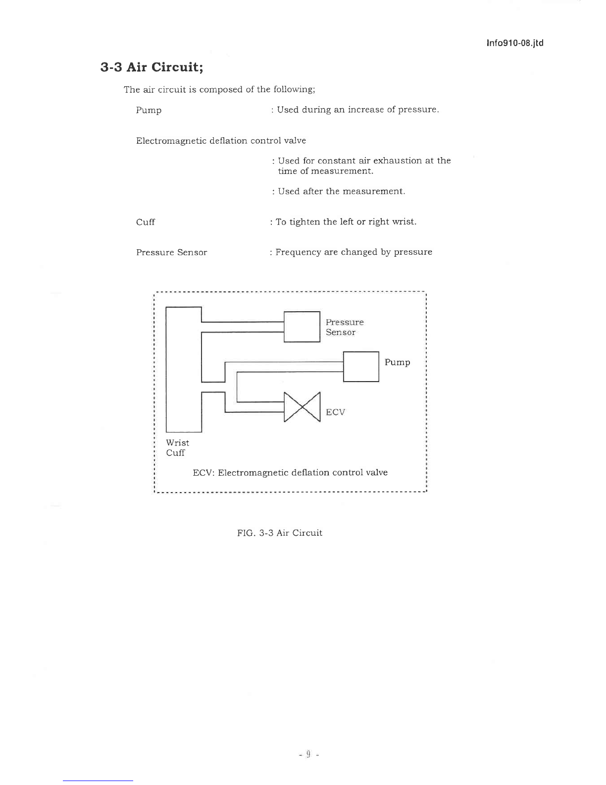
ALP K2 WS-910 User manual

ЛL「 K=°
Sewice Manual
for Diutd Blood Pttsswe MOdtor
MIodel No.WS‑910

lnfo910¨ 08.itd
1.
2.
3.
4.
5.
6.
INDEX
DESCRIPTION
SPECIFICATIONS
PRINCIPLE OF OPERATION
OPERATING INSTRUCTION
ERROR DISPLAY
OUTSIDE DRAWING
PRODUCTION PROCESS TABLE
PRESSURE SENSOR 一――
PRESSURE ACCURACY TEST ―一――――――――――
2
3
5
10
12
13
14
15
16
17
6‑1.MAIN UNIT
6‑2.CUFF UNIT ―
一一―――――
7.
8.
9.
10. EXPLODED VIEWS
10‑1.MAIN UNIT
10‑2.CUFF UNIT
10‑3.PACKING
11. PARTS LIST ――――――――――――――――――― ――――――――――――――――――――――――――
18
19
20
21

info91 0‐ 08.itd
1。 DESCRIPTION
The lvlodel WS‑9 10 is an Auto lnflation Wrist Digital Blood Pressureヽ /1onitor.
The readings in each function are di」 tal diSplayed on 13 digits LCD panel.
STATUS INDICATION shows Palpatolγ ヽVave and BattelyヽVeak.
ERROR MESSAGE CODE includes Batte17 Ⅵ/cak,it is impossible to measure
the blood pressure accurately.
BAttERY POWER is monitored alwtts the batte17 rernnantis sho、 〜
咀on the displaげ .
AUTOMATIC AIR INFLATION iniates the cuffpressure by an mtemal dr pump.
AUTOMATIC AIR DUMP VALVE dumps the pressure in the cuff automatically
、vhen the rneasurement is over or error has been occurred.
AUTOMATIC POWER SHUT OFF;
The unit win autOmaicalサ turl■ Offifit is not operated for
about 3 1ninutes or IInore.
2

lnfo91 0‐ 08,itd
2.SPECIFICATIONS
2‑1.N/1odel WS‐910‐08
2‑2 Classiication CLASS Ⅱa
2‑3.Function O Blood Pressure Mcasurhg
②Pulse Rate Mcasuring
O Automatic Power Shut Off
④
3 Error lndication
2‑4.B.P I Specincations
(1)Measung Method Cuff Oscillo― Metnc
(2)Measu ng Posijon Wst
(3)Coverage、 、Tist circumference 125mm〜 205mm
(4)PresSure detection Pressure to Frequency Converter
(5)PresSure indicaing
(Cuff Pressure) O Units mmHg
EN1060… 16
②Range 0‑300 mmHg
EN1060‑37.7.1
O Resolution llnmHg
EN1060‐37.7.2
O Zero setting Automatic zero setting
EN1060‑37.4.4
(6)Measu ng range O Systolic 50‑250n■mHg Cuff Pressure
②Diastolic 40‑1801■mHg Cuff Pressure
SYS―DIA>10mIInHg
O Pulse Rate 40‑160 Beat/Min.
(7)Accuracy ①Pressure ±
3 mmHg
EN1060‐ 17.1。 1
②Pulse rate ±50/。 of Reading
(8)Cuff inflatlon Automatic lnnation syStem(Att Pump)
(9)Preset pressure 180mmHg(Fed)
(10)Cuff denatlon Electromagnedc de■ation Control Valve(ECV)
(11)Denadon rate 5.5〜 75 mmHg/Sec.
(12)Rapid Exhaust Automatic Exhaust(ECV)
EN1060‐37.4。 3
(13)Cuff System O Cuffof W st
②Lockng Mech―Velcro
O Bladder size 52mm(W)× 128mm(D)
④ Cuff Size 66mm(W)× 280mm(D)
3

lnfo91 0‐ 08.itd
(14)IndiCatOr 1 3Diglts+2 1ndicators
EN1060… 15
0 13 Digits Displ響
′CD Displε ッ
Date/Time
Systolic
Diastolic
Pulse rate
rvlernOry No.
②lndicatOrs Palpatory、Vave
(HCart mark)
V′ eak battew
(15)Memow O Systolic Diastolic and Palse rate
②60 measurement results
O Memo巧 ″Data Average (SYS.DIA.PUL)
(16)ヽノIiCrOcOmputer 8Bitヽ/1icrocomputer TMP86CH29AU‑3D63
A205119‑01
(17)Power SOurce LR03 T,Te(AAA Salze)2 pcs
EN1060…37.3.1
(18)Power COnsumption 2W(Max)
(19)Operaung TEMP./Humidiサ +10℃ to+40℃ /85%RH or below
EN1060‑17.1.2.2
(20)Storage TEMP./Humidit57 ‑5℃ to+50℃ /85%RH or below
EN1060‑37.5。 1
(21)Mttn unit sレ e64 mm(W)× 66.5mm(D)X305mm(H)
(22)Mdn unit Weight Approx.1008111(Not lncluding Batteries)
2‑5. Safeサ system Cuff Pressure> 330 mmHg →Rapld Exhaust
2‑6.Elect cal safety EN1060‐ 17.2.1
2‑7.Resistants to vibra■ on&shock EN1060… 17.2.2
2‑8.Air Leakage EN1060‐37.4.1
2‑9.Electromagnetic compaibility EN1060‑37.5.3
2‑10.Stability of tl■ e cuff pressure indication EN1060‑37.6
2‑11.Overall systern accuracy EN1060‐37.9
2‑12.Lay a pipe system See‖ 10.EXPLODED VIEWS"P18
2‑13.Operating manual English/SpaniSh
2‑14.Accessories Non
2‑15.Life 5 Year

lnfo91 0‐ 08.itd
3。 PRINCIPLES
3‑1。 Operation
OF OPERATION
of Each Unit
These units operate as follo、 vs:
FIG 3‑l Block Diagram
Displ響
Pressure―
Frequency
Converter
A/1icro―
Computer
McIInonr Out SWitch
START(POWER)S、 vitCh
Power
Control
Circult ECV
Drlve
Cttcuit
For other
Circuits
DC/DC
Regulated
3 Volt
(Battev weak Detector)
P/F Converter
C.P.U ECV:Electromagnetic deflauon
Control Valve

info91 0‐ 08.itd
a)PreSSure Sensor
Elasuc capSule Capsule is inflated by pressure.
Parallel Plate variable capacitor;
Gap of parallel plate are changed by inflation.
CR oscillator;
Oscillation frequency are changed by capacitance change
Frequency Counter;
Frequency are counted by counter and digital outputis took
in to the computer
(The COunter is included in to the computer IC chip)
b)omers
Power supply control circuit;
Receives the control signal from the lnicrocomputer to turl■ the
power on and offto units other than the rnicrocomputer.
Displaり Unit;
Displays cuff pressure,maxilnuΠ l blood pressure,mllnum
blood pressure,pulse rate and inforllnation messages.
Electromagnetlc deflation control valve(ECV)d Ve circuit;
ECV d ve circuit controls the alr exl■ aust speed regularly
dung blood pressure rneasuring by the controlling signal from
tlle llnicrocomputer.
It exhausts the alr rapid after■le measuring or when‖ Err"
indicating.
Pump dve cicuit;
Controls staring and stopping ofthe pump.
C)MiCrOcOmputer
According to■ e informatlon received,the lnicrocomputer
controls the P/F converter,blood pressure rneasuring sequence
and LCD display drive.
6

:nfo91 0‐ 08.itd
3‑2 Flow Chart of Operation
Pressure‖ 0‖ set
Pressure displayed
Magnet valve ON
Innation tilner start
nflation imer counter>6 sec.?
Pressure>50 1nmHg?
ECV ON

(180mmHg)
ssurc>330 rnmHg
Magnet valve OFF ssu rc ≧Prcset Prcssurc
nal.。 n tlmcr counter>1 0sec?
Pump stop
Pump stop
nnation enOugh?
set Pressurc>300rnrnH
Displεり
ed
Heart Mark" Preset pressure
l SteD increments
Purnp Start
Pulse rate measu n
Magnet Valve OFF
easurement result displayed
3 11ninutes tilner start
IninutesP
Po、ver OFF
Yes
ECV OFF
Yes
Yes
:nfo91 0‐ 08.itd
Minirnum blood pressure
decisive condition satlsfled ,
Maximum blood
pressure
declslve conditlon
sausfled ?
員o■9■ Wg生 鈎99k
Each Part
V OFF
agnet Valve OFF
Pump stopped
3attev Empサ IndiCate
Each P

info91 0¨ 08.itd
3‐ 3 Air Circuit;
The alr circuit is composed of the follo、 v■ ng;
Pump :Used during an increasc of pressure.
Electromagnetic denation cOntrol valve
Cuff
Pressure Sensor
:Used for constant alr exhaustion at the
tilne of rneasurement.
:Used after the rneasurement.
:To ughten the left or right、 〜
Tist.
:Frequency are changed by pressure
Pump
Wst
Cuff
ECV:Electromagnetlc denatiOn cOntrol valve
FIG.3‑3 Air Circuit

lnfo91 0‐ 08.itd
4。 OPERATIONS INSTRUCTION
4‑l Power Supply
l)In Case using battev
Take off battery cOVer left side ofrnaln body and insert 2 pieces
of LR03 type batteries to flt polarity indication.
4‐ 2 Time set up
l)PuSh the‖ POWER"s、
tch for 2 seconds,the LCD shows all segrnents.
2)Then the LCD showslike FIG 4‑2‑2 after zero blink.
3)Push the・ MEMORYHs、tch for 2 seconds,the LCD shows Time set up mode,
M′ e can change the numerical value of blink up positlon.
Push the‖ POヽVERm switch,valuc are up onc at a time
Push the‖ MEMORY"slvitch,valuc of blink up posi■ on change.
tum:A.D.→ month→ d呼 →
hour→ minute(FIG 4 2‑3)
Retum the time displav after minute set up.
FIG 4‑2‑3 ex)Dec.262001
FIG 4‑2‑2
―
hour rllinute the tirne displ響

:nfo91 0‐ 08.itd
4‐ 3 Measurement Procedures
l)Wrap the cuff around the upper left wrist.
Face upM/ards the palrl■ ofthe hand,make the body position in the center ofthe pall■ ,
and、vTap the cuff tightly to the、vTist,leaving no space bet、 veen the cuff cloth.
In case you、 vear a、vTist watch on your left wnst,please、 vTap cuff after you put offit.
The posi■ on of me individual v′ hen being measured llnay be either lメ ng dOヽヽ
m Or sitting.
In the sitting position hoM′ever make sure that the location on the left、 vTist to be
measured is about at the salnc height as thc heart and that the forearrlll is extended
naturally on the table and does not rnove
2)Push the‖ POWER"su・ltch to automaticall■ ‐
inflate cuff to■ lc Optimum prcssure
3)PresSure start to descend. Please do notlnove your body as possible as you
can later.
Further descending cuff pressure,indication inark for‖ Heart inark"
nashg tO nOtice pulse、 vave、vhen the pulse wave begin to generate.
Further descending cuff pressure and、 vhen come to rnmimurn blood
pressure,display for"Heart lnark‖ nashing also disappear.
lνlinirnum,maxirnum blood pressure and pulse rate is displayed
ヽ
/1casurement is completed above all steps.Then the unit、、
■1l automadcally
exhaust the dr from tl■ e cuff
lf you forget to turn the po、ver s、、
■tch to off after conlpletion of measurement,
it uill be automadcally turned off after the 3 minutes
ln case you take rneasure agall■ ,you should repeat from itcll1 2)to 7)
4‑4 Memory information
l)The unit call store the results of 60 measurements in the memo弓 ヽ
A/1easurement result is automatically stored in tl■ e rllemo弓
「
、Vhen the
flrst measurement is colnpleted
(MCIl10弓「No l indicates the measurement result obtained in the right
previous measuremen■
11
4)
6
7

info910‐08.itd
2)To reCallthe memo7,preSS Memo7 Button,a single push、 五1l recall the results stored
in Memo=yl.Second,third,4,5,6 ・・・
60th pushes on the button will recall the results
in Memories 2,3,4,5,6 ・
・・
60.
The lnemo7 number recalled、 、
■1l be sho、マ
n in the A/1emo7 number Display Area
in the lo、ver right corner ofthe displav panel.
3)You nill sce memow data when)7ou press memow buttOn.First display shows date,systolic,
diastolic pressures ttd memow No.(MEMO#).(2 sec)SeCOnd displtt shows time,systolic,
diastouc pressures and pulse(PUL).(3 sec) First,Second display is repeated 5 tillnes.
repeated 5 tilnes
2 sec 3 sec
4)If yOu press the memow recall button in succession by the number of
tirnes of rnemo理 ′
,and press it agaln after an the lnemow data are recalled,
you can see in the LCD display the average valuc of all stored data of
Systolic blood pressure and the average value of all stored data of diastolic
blood pressure.At the sallne tllne,in the area ofrnemory NO.a letter
[Al as a lnarldng is indicated.
5。 ERROR DISPLAY
This blood pressure monitor displays as error message for mistake measurernent
method and、 veak batte=y
ln case displaying error message dung lneasurement,
please exhaust and please re‑lneasure after conirlning ho、 v to use.
5‑1.Improper pressure
Err 330
・
Innation above 330 mmHg
Err 'Noise is detected by moving body du ng measurement
'The exhaust speed is irregular.
The exhaust speed is higher than 9 mmHg/seC Orlesser than 2 mmHg/Sec
5…2。 Weak battery
WealK batteぃr proVide inadequate voltage for operation of the unit.
Batteries need to be replaced.
■ = 7
lIIIE] コ

lnfo91 0‐ 08.itd
6。 OUTSIDE DRAⅥ NG
6¨ 1.MAIN UNIT
「
1〕
│‐ I半 ‐。│卜 ∝ 0 u Σ
―13

:nfo910¨ 08.itd
6‐2.CUFF UNIT
Bladdcr
Cuff label
Cuff
‑14

info91 0‐ 08.itd
7.PRODUCTION PROCESS TABLE
15
Inspection
Printed cicuit
board assemb Assembly Ad」 ustment
Electronic components
Inspection
Pressure Sensor Ad」 ustment
Structural Parts receiving and inspection
Cabinet Cuff、
Final assemb
Assembけ inspeCtiOn
Attusl‐lent
Shipping

lnfo91 0¨ 08.itd
8. PRESSURE SENSOR
8‐ l Model : csloo
8‑2 Construction :Pressure/Frequency Converter
variable
Capac■ tor
8‑3 Usage Condition
(1)Pressure rall■ ge
(2)Safeち″
OVer 10ad
(3)Compensauon temperature range
(4)Storage temperature range
(5)Humidiサ
(6)Power Supply
8‑4(Dutline
Outline dilnension
ヽVeight
8‑5 Perforlmance
5‑1 0utput frequency
5‑2 Lineariサ
5‑3 Hysteresis
5‑4 Span drift
0〜 300 mmHg
390 11nmHg
O 〜
50℃
‑34 へ´
65℃
85%Rh or below
3V±0.2V
19X19× H13.5mm
Approx.7g
O mmHg :800 KHz± 300 KHz
300 mmHg:fO‑240 KHz
With ±
0.3%of FS
Within± 0.3%of FS
±
1%(10℃ 〜45℃ )
・fO
CS‐ 100 0utline Drawing
.´ 19 、

lnfo91 0¨ 08.itd
9.PRESSURE ACCURACY TEST
Connection、潤ith Test De ce
l Connect a 3V DC power supplyin off mode
2.Connect the standard llnanometer and the innation
diverge to」 oin the connector used for the pressure cylinder,then rnake it
accuracy test on the unit
3.
Test method
l Open theil■ ■
ation cylinder,then turn on the power supply
2.Press the start s、 、
■tch and hold it until"O"starts to flash on the display.
The unit goesto TEST MODE as● vo"0‖ s appear on the displε y
Close the innation cylinder,then turl■ the cylinder handle to inflate alr
until a reading of 50 1nmHg on the standard lnanometer is obtahed.
At that ume,the display of the unit should sho、 v"5050‖ instead of
the‖ 00‖ rnentioned Step 2 above. Both numbers‖ 5050‖ should not
deviate too much 50± 3 at the rnost
Do the check described in Step 3 above at l00,150,200,250,and 300 1nlnHg
as well(± 3 mmHg).
17
Standard
Manometer
Power Supply

lnfo91 0‐ 08.itd
10。 EXPLODED VIEWS
10‐ 1。 MAIN UNIT
1上 `
――
│、こ
´
二
ヽ
、
、
、
19
︵
︲6︶ ︵
′︲7
ヽ︶︵
︲8t
︵ ︲
3 一
ヽ
14サ
15)
1爾
・――
111
‑18‑

info910‐08.itd
10‐2.CUFF UNIT
121
‑19‑
Table of contents
Other ALP K2 Blood Pressure Monitor manuals