CORNING Stripettor Ultra User manual

Corning® Stripettor™ Ultra
Pipet Controller
Instruction Manual
Bedienungsanleitung
Mode de'emploi
Manual de Instrucciones
Manual de Instruções
Instrukcja Obsługi
И струкция Oбслужива ия
取扱説明書

12
1
2
3
4 5
DC
DC
EK
L
F
G
H
J
A
B
O
ENGLISH
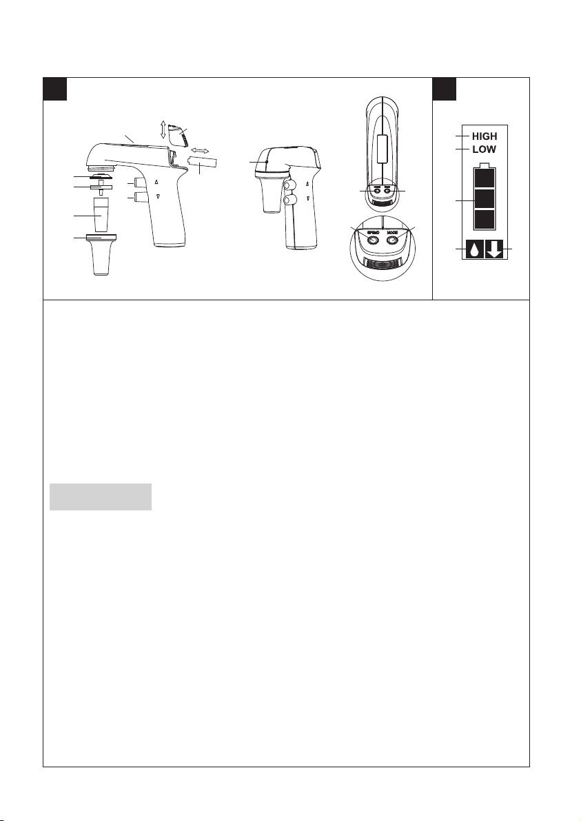
A- Aspira ion bu on - PP
B-Dispense bu on - PP
C-Suc ion speed swi ch - PP
D-Dispense mode swi ch - PP
E-Display
F-Nose piece - PP
G - Pipe holder - SI
H-Membrane fil er - PP/PTFE
J-Connec or gaske - SI
K-Ba ery cover - PP
L-Ba ery - NiMHH, AAA, 1.2V
M- Wall moun - PP
N-Charger 9V: EU, US, UK, AU
INPUT: 100-240V, 50/60Hz,
0.3A
OUTPUT: AC DC 9V, 230mA
O - Direc ou le of liquid vapors
Casing -PP
DEUTSCH
A-En nahme as e -PP
B-Ausgabe as e -PP
C-Geschwindigkei sschal er -PP
D-Schal er der
Ausgabebe riebsar -PP
E - Anzeige
F-Schu zabdeckung für den
Hal er -PP
G - Pipe enhal er -SI
H-Membranfil er -PP/PTFE
J-Dich ung des
Verbindungss ückes -SI
K-Akku-Deckel -PP
L-Akku - NiMH, AAA, 1.2V
M- Wandhal erung -PP
N-Ladegerä 9V: EU, US, UK, AU
INPUT: 100-240V, 50/60Hz,
0.3A
OUTPUT: AC DC 9V, 230mA
O - Direk er Aus ri der
Flüssigkei sdämpfe
Gehäuse -PP
FRANÇAIS
A-
Bou on poussoir d'aspira ion -PP
B-Bou on-poussoir
de refoulemen - PP
C-Sélec eur de vi esse -PP
D-Sélec eur du mode de
refoulemen -PP
E-Ecran
F-Embou de fixa ion -PP
G-Pince (fixa ion) de la pipe e -SI
H-Fil re à membrane -PP/PTFE
J-Join de raccord -SI
K-Couvercle des accumula eurs
-PP
L-Accumula eur
- NiMH, AAA, 1.2V
M- Suppor mural -PP
N-Chargeur 9V: EU, US, UK, AU
ENTREE: 100-240V, 50/60Hz,
0.3A
SORTIE: AC DC 9V, 230mA
O - Sor ie direc e des vapeurs de
liquide
Suppor -PP
ESPAÑOL
A-Bo ón de succión -PP
B-Bo ón de dispensación -PP
C-Selec or de velocidad -PP
D-Selec or de modo de
dispensación -PP
E-Pan alla
F-Cono de pro ección PP
G-Boquilla de conexión para
pipe a -SI
H-Membrana fil ran e -PP/PTFE
J-Jun a de acople -SI
K-Cubier a de la ba eria -PP
L-Ba ería: Ni-MH - NiMH, AAA,
1.2V
M- Percha -PP
N-Cargador 9V: EU, US, UK, AU
INPUT: 100-240V, 50/60Hz,
0.3A
OUTPUT: AC DC 9V, 230mA
O - Salida direc a de los vapores de
líquidos
Carcaza: PP
PORTUGUÊS
A- Bo ão de aspiração -PP
B-Bo ão para esvaziar -PP
C-Sele or de velocidade de sucção
– PP
D-Sele or do modo de
esvaziamen o -PP
E-Display
F-Cone de pro eção -PP
G-Supor e da pipe a -SI
H-Membrana fil ran e -PP/PTFE
J-Jun a de conexão -SI
K-Tampa das ba erias -PP
L-Ba eria
- NiMH, AAA 900mAh, 1.2V
M- Supor e -PP
N-Carregador 9V: EU, US, UK, AU
ENTRADA: 100-240V, 50/60Hz,
0.3A
saída: AC DC 9V, 230mA
O - Tomada direc a de vapores do
líquido
Caixa -PP
POLSKI
A-Przycisk pobierania -PP
B-Przycisk wydawania -PP
C-Przełącznik prędkości
pobierania -PP
D-Przełącznik rybu wydawania
-PP
E-Wyświe lacz
F-Osłona uchwy u pipe y -PP
G-Uchwy pipe y -SI
H-Fil r membranowy -PP/PTFE
J-Uszczelka łącznika -SI
K-Pokrywka akumula orów -PP
L-Akumula or - NiMHH, AAA,
1,2V
M- Wieszak -PP
N-Ładowarka 9V: EU, US, UK, AU
INPUT: 100-240V, 50/60Hz,
0.3A
OUTPUT: AC DC 9V, 230mA
O - Wylo oparów
Obudowa -PP
êìëëäàâ
A-äÌÓÔ͇ ̇ÔÓÎÌÂÌËfl -PP
B-äÌÓÔ͇ ÒÎË‚‡ -PP
C-èÂÂÍβ˜‡ÚÂθ ÒÍÓÓÒÚË
‚Ò‡Ò˚‚‡ÌËfl -PP
D-èÂÂÍβ˜‡ÚÂθ ÂÊËχ
ÒÎË‚‡-PP
E-ÑËÒÔÎÂÈ
F-äÓÌÛÒ -PP
G-ÑÂʇÚÂθ ÔËÔÂÚÍË -SI
H-
åÂÏ·‡ÌÌ˚È ÙËÎ¸Ú - PP/PTFE
J-èÓÍ·‰Í‡ ÒÓ‰ËÌËÚÂÎfl -SI
K-äp˚¯Í‡ ‡ÍÍÛÏÛÎflÚÓÓ‚ - PP
-ÄÍÍÛÏÛÎflÚÓ - NiMHH, AAA,
1,2V
M-ç‡ÒÚÂÌÌ˚È ÍÂÔÂÊ - PP
N-á‡fl‰ÌÓ ÛÒÚÓÈÒÚ‚Ó 9V: EU,
US, UK, AU
INPUT: 100-240V, 50/60Hz, 0.3A
OUTPUT: AC DC 9V, 230mA
O-éÚ‚ÂÒÚË ÔflÏÓ„Ó ‚˚ÔÛÒ͇
ÊˉÍËı Ô‡Ó‚
äÓÔÛÒ - PP
日本語
A - 吸引ボタン - PPB - 排出ボタン - PPC - 吸引速度スイッチ - PPD - 排出モード切り替えスイッチ - PPE - 液晶ディスプレイF - ノーズピース - PPG - ピペットホルダー - SIH - メンブレンフィルター - PP/ PTFEJ - コネクタガスケット - SIK - 電池カバー - PPL - 充電池 - ニッケル水素、単4、1.2VM - 壁掛けホルダー - PPN - 充電器9V:EU、米国、英国、オーストラリアINPUT:100-240V、50/60Hzの、0.3A出力:AC DC9V、230ミリアンペアO - 液気拡散口ケーシング - PPPP : ポリプロピレンPTFE: ポリテトラフルオロエチレンSI: シリコン
PP: Polypropylene
PTFE: Poly e rafluoroe hylene
SI: Silicone

3
4
5 6
1234
B C DA
7 8
F
G
H
M
N
AC
B
L

Table of contents
1. Introduction .................................................................................................................................... 2
2. Work safety instructions .............................................................................................................. 2
3. Limitations of use .......................................................................................................................... 3
4. Switching on ................................................................................................................................... 3
5. Aspirating and dispensing liquids ............................................................................................. 3
6. Troubleshooting ............................................................................................................................. 5
7. Replacing the filter ........................................................................................................................ 6
8. Charging the batteries .................................................................................................................. 6
9. Maintenance ................................................................................................................................... 7
10. Components ................................................................................................................................... 7
11. Ordering information ................................................................................................................... 8
12. Spare parts ...................................................................................................................................... 8
13. Product disposal .............................................................................................................................8
1

1. Introduction
The pipet controller is a device intended for pipetting liquids with the use of measuring
pipets. It can work with all types of glass or plastic pipets in the volume range from 0.5 mL
to 100 mL.
Two dispense modes permit selection of dispensing intensity depending on the user's needs.
The selected setting of the pipet controller mode is shown on the display (Figure 1E).
Figure 1 shows the external parts of the pipet controller with a description of the materials
used.
Display indicators are shown in Figure 2.
2. Work safety instructions
WARNING! Risk of inju y
CAUTION: Risk of damage to the device o e o s in pipetting of liquids
Before starting the work with the pipet controller every user should read these operating
instructions carefully.
CAUTION:
• Using the device inconsistently with the operating instructions may result in damaging
the device.
• The device should be serviced only at an authorized service center, otherwise
the manu fac turer will be relieved from any liability under the warranty.
• Only original spare parts and accessories, recommended by the manufacturer, shall be
used.
• Only the original charger, supplied by the manufacturer, shall be used for charging
the batteries.
• In case of incorrect functioning of the pipet controller, work shall be stopped. The device
shall be cleaned according to section 9 and sent for repair to an authorized service center.
• In the case of mechanical damage to the casing, the device shall be immediately sent for
repair to an authorized service center.
• The use of excessive force during work shall be avoided.
WARNING!
• During the work with the pipet controller general safety regulations regarding risks related
with laboratory work should be observed. Protective clothing, goggles, and gloves should
be worn.
• The pipet controller shall be used only for measuring liquids in conditions specified
by the ma nufacturer, which are limited due to the chemical and mechanical resistance
of the device, as well as the user safety.
• The information and instructions provided by the manufacturers of the reagents must be
ob served.
Note: The pipet cont olle is equipped with liquid vapo s exhaustion system which p otects
against co osion to ensu e long inst ument life.
ENGLISH
2

3. Limitations of use
• The pipet controller shall not be used for measuring substances with vapours of which
damage the following plastics: PP, SI, EPDM, POM.
• The pipet controller shall not be used in an environment where explosion risk is present.
• Flammable liquids shall not be measured – in particular substances with flash-point below
0°C (ether, acetone).
• The pipet controller shall not be used for drawing acids with a concentration above
1 mol/L.
• The pipet controller shall not be used for drawing solutions with a temperature
above 50°C.
• The pipet controller may work in temperature range from +10°C to +35°C.
The pipet controller is suitable for general laboratory use only. It must be used only by
personnel who know the health risks associated with the substances that are normally
used with this instrument.
4. Switching on
The pipet controller is switched on by pressing any of the buttons (Figure 1A, B, C, D).
The display will show the selected aspiration mode, dispense mode and the batteries
level indicator. Examples of the display indications are shown in (Figure 5). The batteries
are discharged and require charging if the indicator does not display "bars" (Figure 5.4).
When the batteries are fully charged, the indicator displays three “bars” (Figure 5.1).
• The pipet controller switches off automatically if not used for 5 minutes.
• The pipet controller may be charged only with the original charger.
• The mains voltage shall conform with the specification on the charger.
• Charging shall be done in accordance with section 8 of the instruction manual.
5. As irating and dis ensing liquids
Attaching a pipet
CAUTION: Before attaching a pipet, check whether the pipet is not damaged, has no dents
or sharp edges in the gripping part. Check whether the gripping part is dry.
The pipet shall be gripped as close to the upper end as possible and carefully inserted into
the pipet holder until resistance is noticed (Figure 3A).
WARNING!
Do not apply excessive force so as not to damage thin pipets and avoid risk of injury.
A pipet that has been correctly attached and sealed in the holder should not tilt to the sides.
After attaching a pipet, hold the pipet controller in a vertical position. It is not recommended
to leave the device with a pipet attached for a longer period, for example overnight or over
a weekend.
CAUTION: Do not put aside the pipet controller if there is liquid in the pipet.
3

Filling the pipet
Before aspirating is started, set the speed by pressing the SPEED switch (Figure 1C) until
the display shows the correct speed (Figure 1E).
• HIGH speed - fast aspirating (Figure 2.1),
• LOW speed - slow aspirating (Figure 2.2).
It is recommended to set the LOW speed when working with pipets of volumes up to 5 mL,
and the HIGH speed for pipets of volumes greater than 5 mL. Holding the pipet controller
in a vertical position, immerse the pipet end in the liquid to be drawn up (Figure 3B),
and press the aspiration button gently. The speed depends on how deep the aspirating
button has been pressed. The deeper the button is pressed the faster the liquid is aspirated
into the pipet.
It is recommended to draw a slightly greater liquid volume than required (due to meniscus
above the required volume mark), adjusting the aspiration speed, so as not to overfill the
pipet.
Setting the volume
After the pipet is filled, dry the outside surface with absorbent paper that does not leave
impurities. Then set the required liquid volume precisely. Pressing the dispense button gen-
tly (Figure 3C), dispense the excessive liquid from the pipet until the meniscus of the liquid
aligns exactly with the required volume mark on the pipet.
Emptying the pipet
Holding the vessel in an inclined position, place the pipet end in contact with the vessel wall
and press the dispense button gently (Figure 3C). The dispensing intensity may be adjusted
depending on how deep the dispense button has been pressed. The deeper the button is
pressed the faster the outflow of liquid from the pipet.
The pipet controller has two dispense modes. The dispense mode is selected by successive
pressing the MODE switch (Figure 1D) until the display shows the correct mode (Figure 1E).
• Gravity mode marked with the icon on the display (Figure 2.4) – dispensing is effected
in gravity mode, which means that the liquid flows out of the pipet by its own weight.
• Blow out mode marked with the icon on the display (Figure 2.5) – dispensing is effected
in gravity mode, however, when the dispense button is pressed to the middle position,
the pump is started and fast emptying of the pipet with a blow out is effected.
CAUTION:
During gravimetrical dispensing the pipet is not completely emptied due to the characte -
ristics of pipets used with the pipet controller.
ENGLISH
4

6. Troubleshooting
If during your work the functioning of the pipet controller is incorrect, check the cause
and remove the fault.
If the above actions do not help, the device shall be sent to the nearest authorized service
center.
Before being serviced, the pipet controller should be cleaned and decontaminated.
Written details including the precise specification of solutions used and the type
of laboratory in which the device was used, should be sent with the product.
Problem Possible Cause Action
The pipet falls out
(the holding force
of the pipet is too small),
or tilts to the side too much.
The pipet holder is dirty or
wet (Figure 1G).
Take out the pipet holder,
then clean, wash, and dry it.
The pipet holder is damaged. Replace the holder with
a new one.
The pump is working, but
the pipet controller aid does
not draw liquid or draws
liquid very slowly.
The filter is dirty (Figure 1H).
Take out the pipet holder,
take out the filter,
if it is dirty, replace it with
a new one.
The pipet holder
and/or the connector gasket
is damaged (Figure 1J).
Replace the mechanically
damaged elements with
new ones.
Liquid leaks from the pipet
(the aspiration
and the dispense buttons
are not pressed).
The pipet is damaged.
Check the pipet for damage
(cracks, dents). If present,
repla ce the pipet with
a new one.
The pipet is inserted incor-
rectly.
Check whether the pipet has
been correctly inserted in the
holder.
The pipet holder, the filter,
or the connector gasket
is installed incorrectly.
Check whether all parts are
pre sent and correctly
installed.
The pipet holder and/or the
connector gasket is damaged
(Figure 1G, Figure 1J).
Replace the mechanically
damaged elements with
new ones.
5

7. Re lacing the filter
CAUTION:
The work safety instructions given in section 2 shall be observed when disassembling
the pipet controller.
The filter replacement is necessary, if drawing efficiency deterioration is observed.
The direct reason may be a dirty filter after a long period of use.
In order to replace the filter:
• Remove the pipet.
• Unscrew the nose piece (Figure 4A).
• Remove the membrane filter (Figure 4A) and the pipet holder (Figure 4B).
• Rinse the holder using a wash bottle (Figure 4C).
• Blow liquid out of the holder and set it aside until it is completely dry.
• Install new membrane filter (Figure 4D) and assemble the device in reverse order.
8. Charging the batteries
CAUTION!
The pipet controller may be charged only with the original charger. The main voltage must
conform with the specification on the charger.
Using chargers other than the original one may damage the battery.
The pipet controller is delivered with 3 NiMH type AAA batteries.
The batteries can be replaced easily if necessary after the battery cover is taken off
(Figure 1K). The manner in which the batteries are arranged is shown in Figure 8.
Cha ging:
1. Charging temperature: 10°C to 35°C.
2. Charging the battery is carried out through a charger (power supply) by direct connection
to the main power. Batteries charging is indicated by successive lighting of “bars”.
3. Full charging time: 7 to 8 hours.
4. The batteries are charged when all 3 “bars” are displayed simultaneously
(Figure 5.1).
When the batteries are charged, the charging circuit disconnects automatically.
The service life of the batteries: approx. 1,000 charging cycles, if used correctly.
It is not possible to overcharge the batteries if all instructions of the manufacturer
are followed.
ENGLISH
6

WARNING!
If disposable batteries are used, it is unacceptable to connect the device to the charger.
In order to prolong the life span of the rechargeable batteries, the following rules should
be followed:
1. Before the pipet controller is activated for the first time, the batteries should be charged.
2. If the pipet controller starts to indicate low battery level during work, connect it to the
power supply to continue working.
3. Do not leave the pipet controller discharged for a long period of time.
4. In case of a planned longer break in using the device, it is recommended to remove
the batteries from the battery compartment or charge them every few months.
9. Maintenance
Cleaning
The pipet controller does not require any maintenance. Its external parts may be cleaned
with a swab moistened with isopropyl alcohol.
The nose piece and the pipet holder may be autoclaved at 121°C for 20 mi nutes.
After autoclaving, dry the pipet holder. The filter included in the set may be sterilized
by autoclaving at 121°C for not more than 15 minutes.
Ult a violet (UV) ste ilization
The outer body of the pipet controller is UV resistant, which was confirmed by many tests.
The recommended distance from the radiation source to exposed element should be not less
than 50 cm.
Prolonged and very intense UV exposure can cause de-coloration of pipet controller parts,
without affecting its performance.
Sto age
The pipet controller should be stored in a dry place. The allowable storage temperature:
-20°C to +50°C.
During breaks in the work the pipet controller can be stored on the wall hanger.
CAUTION:
Do not store the pipet controller with a filled pipet.
10. Com onents
The pipet controller set is supplied with the following components:
• Universal charger with set of adapters
• Membrane filter 0.2 µm (3)
• Batteries (3 AAA)
• Instruction manual
• Wall hanger
• Set of colored nose pieces (3: yellow, green, red)
7

ENGLISH
8
11. Ordering information
The Corning® Stripettor™ Ultra Pipet Controller (Cat. No. 4099) comes with a universal charg-
er
and a set of adapters in different versions: EU, US, UK, and AUS. Choose your country's
adapter and connect to the housing.
To mount the adapter, it should be inserted into the slots of the housing in the direction
of the arrow (1), until you hear a click (Figure 6).
To remove or change the adapter, simply press the “PUSH” button in the direction
of the arrow (2), hold the button down, remove the adapter in the direction of the arrow (3).
12. S are arts for Corning Cat. No. 4099
13. Product dis osal
According to Directive 2012/19/EU of the European Parliament and Council of 4th July 2012
on waste electrical and electronic equipment (WEEE) as amended, the Corning® Stripettor™
Ultra Pipet Controller is marked with the crossed-out wheeled bin and must not be disposed
of with domestic waste.
Consequently, the buyer shall follow the instructions for reuse and recycling of waste
electronic and electrical equipment (WEEE) provided with the products and available
at the following link:
www.corning.com/weee.
The crossed out wheeled bin symbol is printed in the product instruction
manual and on the packaging to indicate that, in accordance
with the requirements of Directive 2006/66/EC of 6th September 2006
on batteries and accumulators and waste batteries and accumulators,
batteries must be disposed of accordance with national regulations.
For additional product information, visit
www.corning.com/lifesciences
,
or call 1.800.492.1110. Customers outside the United States, call 1.978.442.2200
or contact your local support office.
Item
in Figure 1 Descri tion Corning Cat. No. Qty/Pk
FSet of colored nose pieces
(4: orange, yellow, green, red) 4997 4
G Silicone pipet holder 4993 1
HMembrane filter 0.2
µ
m 4991 5
Membrane filter 0.45
µ
m 4992 5
L Battery set - NiMH, AAA, 1.2V 4994 3
NUniversal power supply with set of
adapters 9V: EU, US, UK, AUS 4996 1
All rights reserved. Product described in this manual is subject to availability and technical modification. Errors excepted.
Corning Incorporated reserves the right to improve, enhance, or otherwise modify its products without prior notification.
© 2016 Corning Incorporated

Inhaltsverzeichnis
1. Einführung ..................................................................................................................................... 10
2. Sicherheit ....................................................................................................................................... 10
3. Anwendungsbeschränkungen für den Einsatz .................................................................... 11
4. Inbetriebnahme............................................................................................................................ 11
5. Entnahme und Abgabe von Flüssigkeit ................................................................................. 11
6. Fehlerbeseitigung ........................................................................................................................ 13
7. Filteraustausch.............................................................................................................................. 14
8. Laden des Akkus ........................................................................................................................... 14
9. Wartung ......................................................................................................................................... 15
10. Lieferumfang................................................................................................................................. 15
11. Angaben zur Bestellangaben ................................................................................................... 16
12. Ersatzteile ..................................................................................................................................... 16
13. Produktentsorgung .....................................................................................................................16
9

1. Einführung
Die Pipettierhilfe dient zum Abmessen von Flüssigkeit mittels Messpipetten. Das Gerät
ist für alle Pipetten (Kunststoff und Glas) mit einem Volumen von 0,5 ml bis 100 ml
geeignet. Zwei Ausgabemodi erlauben die Wahl der Ausgabeart entsprechend den
Bedürfnissen
des Benutzers. Die gewählte Einstellung der Funktionen der Pipettierhilfe erscheint in der
Anzeige (Abb. 1E).
Auf Abb. 1 sind die von außen sichtbaren Komponenten der Pipettierhilfe (mit Angabe
des jeweils eingesetzten Materials) dargestellt. In Abb. 2 ist die Anzeige dargestellt.
2. Sicherheit
WARNUNG! Ve letzungsgefah
ACHTUNG: Risiko de Beschädigung ode de fehle haften Flüssigkeitsmessung
Machen Sie sich vor dem Einsatz der Pipettierhilfe mit dieser Betriebsanleitung vertraut.
ACHTUNG:
• Das Gerät kann beschädigt werden, falls es entgegen den Richtlinien der Betriebsanleitung
benutzt wird.
• Serviceleistungen dürfen nur in autorisierten Vertragswerkstätten vorgenommen werden,
andernfalls übernimmt der Hersteller keine Gewährleistung.
• Verwenden Sie ausschließlich vom Hersteller empfohlene Original-Ersatzteile und Zubehör.
Zweifel sind mit dem Hersteller oder Regionalvertreter zu klären.
• Für Akkuladung ausschließlich firmeneigenes Akkuladegerät verwenden.
• Unterbrechen Sie die Arbeit bei inkorrekter Funktionsweise. Reinigen Sie das Gerät gemäß
Bedienungsanleitung /oder senden Sie es einer autorisierten Vertragswerkstatt zur
Reparatur.
• Bei einer mechanischen Beschädigung des Gehäuses senden Sie das Gerät zur Reparatur
in eine autorisierte Vertragswerkstatt.
• Vermeiden Sie bei der Handhabung übermäßigen Krafteinsatz.
WARNUNG!
• Beachten Sie bei der Handhabung der Pipettierhilfe die allgemeinen Laborsicherheits -
vorsch riften. Tragen Sie Schutzkleidung, eine Schutzbrille sowie Schutz handschuhe.
• Die Pipettierhilfe darf nur zum Abmessen von Flüssigkeiten unter den vom Hersteller
angegebenen Bedingungen verwendet werden. Diese Bedingungen sind aufgrund der
chemischen und mechanischen Beständigkeit des Geräts und der Sicherheit des Nutzers
begrenzt.
• Beachten Sie die Angaben und Richtlinien der Reagenz-Hersteller.
Hinweis: Die Pipettie hilfe ist mit einem Flüssigkeits-Dampf Absaugsystem ausgestattet, das
vo Ko osion schützt und eine lange Lebensdaue gewäh leistet.
DEUTSCH
10

3. Anwendungsbeschränkungen für den Einsatz
• Verwenden Sie die Pipettierhilfe nicht zum Abmessen von Substanzen, deren Dämpfe
die folgenden Materialien zerstören: PP, SI, EPDM, POM.
• Verwenden Sie die Pipettierhilfe nicht in einer explosionsgefährdenden Atmosphäre.
• Pipettieren Sie keine leicht entzündbaren Flüssigkeiten - insbesondere Substanzen mit
einer Entflammungstemperatur unter 0°C (Äther, Azeton).
• Pipettieren Sie keine Säuren mit einer Konzentration von mehr als 1 mol/L.
• Pipettieren Sie keine Lösungen mit Temperaturen von über 50°C.
• Die Pipettierhilfe kann bei einer Temperatur von +10°C bis +35°C eingesetzt werden.
Die Pipettierhilfe ist nur zum allgemeinen Laborgebrauch geeignet. Sie darf nur von
Mitarbeitern angewendet werden, die die gesundheitlichen Risiken, verbunden mit den
Substanzen, die normalerweise mit diesem Instrument verarbeitet werden, kennen.
4. Inbetriebnahme
Die Pipettierhilfe wird durch Drücken einer beliebigen Taste eingeschaltet (Abb. 1A, B, C, D).
In der Anzeige erscheint der eingestellte Entnahmemodus, Abgabemodus sowie der
Ladezustand der Akkus. Anzeigebeispiele zeigt Abb. 5. Die Akkus sind leer und müssen neu
geladen werden, wenn keine Segmente auf der Anzeige mehr leuchten (Abb. 5.4). Bei vollen
Akkus werden 3 Segmente angezeigt (Abb. 5.1).
• Nach 5 Minuten Stillstand schaltet die Pipettierhilfe automatisch ab.
• Die Pipettierhilfe darf nur mit dem Original-Ladegerät aufgeladen werden.
• Die Netzspannung muss mit der Kennzeichnung auf dem Ladegerät übereinstimmen.
• Details zum Aufladen siehe Punkt 8 der Betriebsanleitung.
5. Entnahme und Abgabe von Flüssigkeit
Befestigung de Pipette.
ACHTUNG:
Bevor Sie die Pipette befestigen, ist sicherzustellen, dass sie nicht beschädigt ist und keine
Absplitterungen und scharfen Kanten am Halterteil hat. Prüfen Sie, ob das Halterteil trocken
ist.
Halten Sie die Pipette so weit oben wie möglich. Führen Sie die Pipette vorsichtig bis zum
Anschlag in den Halter der Pipettierhilfe. (Abb. 3A).
WARNUNG!
Vermeiden Sie übermäßigen Kraftaufwand, da die dünnen Pipetten leicht brechen und man
sich schnell verletzen kann. Die gut im Halter befestigte und abgedichtete Pipette darf sich
nicht seitlich verschieben.
Halten Sie nach dem Befestigen der Pipette das Gerät so, dass sich die Pipette in
Senkrechtstellung befindet. Es empfiehlt sich, das Gerät nach dem Abschluss der Arbeiten
für längere Zeit, z.B. nachts oder übers Wochenende, nicht mit montierter Pipette abzulegen.
ACHTUNG:
Legen Sie die Pipettierhilfe nie ab, wenn sich Flüssigkeit in der Pipette befindet.
11

Füllen de Pipette
Vor der Entnahme ist die Geschwindigkeit einzustellen. Dazu ist die Taste SPEED (Abb. 1C)
zu drücken, bis der entsprechende Wert in der Anzeige (Abb. 1E) erscheint.
• Stellung HIGH - Schnellentnahme bei Volumen ab 5 ml (Abb. 2.1),
• Stellung LOW - Langsamentnahme bei Volumen bis 5 ml (Abb. 2.2).
Es wird empfohlen, die LOW-Stellung für Pipetten mit einem Volumen von bis zu 5 ml
und die HIGH-Stellung für Pipetten mit einem Volumen von über 5 ml zu wählen.
Halten Sie die Pipettierhilfe so, dass sich die Pipette in Senkrechtstellung befindet.
Tauchen Sie die Pipettenspitze in die zu entnehmende Flüssigkeit (Abb. 3B) und drücken Sie
die Entnahmetaste leicht. Die Ansauggeschwindigkeit hängt davon ab, wie weit Sie
die Entnahmetaste drücken, d.h. je weiter gedrückt wird, desto schneller wird Flüssigkeit
in die Pipette gefüllt.
Es wird empfohlen, etwas mehr Flüssigkeit zu entnehmen, als benötigt wird (der Meniskus
über der Marke des geforderten Volumens). Reduzieren Sie die Ansauggeschwindigkeit in
der Endphase der Entnahme damit die Pipette nicht überfüllt wird.
Einstellung des Volumens
Nach dem Füllen der Pipette ist die Pipettenspitze mit einem saugfähigen Papier zu trocknen,
um Reste der Lösung an der Außenflache der Pipette zu beseitigen. Das geforderte Volumen
stellen Sie ein, indem Sie überschüssige Flüssigkeit aus der Pipette entfernen. Dazu drücken
Sie vorsichtig die Abgabetaste (Abb. 3C), bis der Meniskus der Flüssigkeit genau mit der
geforderten Volumenmarke auf der Pipette übereinstimmt.
Entlee en de Pipette
Halten Sie das Gefäß schräg und legen Sie die Pipettenspitze an die Gefäßwand an. Drücken
Sie vorsichtig die Abgabetaste. (Abb. 3C). Die Abgabegeschwindigkeit hängt davon ab, wie
weit die Abgabetaste gedrückt wird, d.h. je weiter gedrückt wird, desto schneller tritt
Flüssigkeit aus.
Die Pipettierhilfe hat zwei Abgabe-Modi. Der Abgabemodus wird durch aufeinanderfolgen-
des Drücken der Taste MODE (Abb. 1D) gewählt, bis der entsprechende Modus in der Anzeige
(Abb. 1E) erscheint.
• Die Gravitationsabgabe ist mit dem Symbol in der Anzeige (Abb. 2.4) dargestellt
- die Abgabe erfolgt im Gravitationsmodus, die Flüssigkeit fließt infolge des Eigengewichts
aus der Pipette. Die Schnelligkeit des Ausflusses hängt davon ab, wie weit die Abgabetaste
gedrückt wird.
• Die Zwangsabgabe durch Ausblasen ist mit dem Symbol in der Anzeige (Abb. 2.5)
dargestellt - Die Abgabe erfolgt im Gravitationsmodus. Nach dem Drücken
der Abgabetaste bis zur Hälfte, schaltet sich eine Pumpe ein, woraufhin Schnellentleerung
der Pipette durch Ausblasen erfolgt.
ACHTUNG:
Während der gravimetrischen Abgabe wird die Pipette aufgrund von physikalischen
Eigenschaften der verwendeten Pipetten nicht vollständig geleert.
DEUTSCH
12

6. Fehlerbeseitigung
Falls während der Arbeit Unzulänglichkeiten in der Funktionsweise der Pipettierhilfe
festgestellt werden, sind die Ursachen zu bestimmen und Fehler zu beseitigen.
Falls der Fehler nicht behoben werden konnte, schicken Sie die Pipettierhilfe bitte an das
nächstgelegene Service Center. Vor dem Versand muss das Gerät gereinigt und sterilisiert
werden. Legen Sie bitte das ausgefüllte Formblatt bei und geben Sie die genaue
Spezifizierung der eingesetzten Lösungen an und die Art des Labors, wo das Gerät eingesetzt
wurde.
Problem Mögliche Ursache Maßnahme
Die Pipette fällt heraus
(zu geringe Haltekraft der
Pipette), starke seitliche
Bewegungsfreiheit.
Verunreinigter, nasser
Pipettenhalter (Abb. 1G).
Den Pipettenhalter
herausnehmen, reinigen,
abspülen und trocknen.
Beschädigter Pipettenhalter. Den Pipettenhalter gegen
einen neuen austauschen.
Die Pumpe funktioniert
nicht, mit der Pipettier hilfe
kann keine Entnahme
vorgenommen werden oder
diese erfolgt sehr langsam.
Verunreinigtes Filter.
(Abb. 1H)
Den Pipettenhalter heraus-
nehmen, Filter herausneh-
men. Wenn es verschmutzt
ist, durch ein neues ersetzen.
Beschädigter Pipetten hal ter
und/oder beschädigte
Dichtung des Verbin -
dungsstüc kes (Abb. 1J).
Mechanisch beschädigte
Teile gegen neue
austauschen.
Flüssigkeit tropft aus
der Pipette (Entnahmetaste
sowie Ausgabetaste sind
nicht gedrückt).
Beschädigte Pipette.
Prüfen, ob die eingesetzte
Pipette beschädigt
ist- Sprünge, Absplitterungen.
Wenn dies der Fall ist,
die Pipette gegen eine neue
austauschen.
Falsch befestigte Pipette. Prüfen, ob die Pipette kor
rekt
im Halter befestigt wurde.
Pipettenhalter, Filter oder
Dichtung des Verbindung s -
stüc kes sind falsch montiert.
Prüfen, ob alle Teile da
sind und korrekt montiert
wurden.
Pipettenhalter, Filter oder
Dichtung des
Verbindungs stückes sind
falsch montiert.
Mechanisch beschädigte
Teile gegen neue
austauschen.
13

7. Filteraustausch
ACHTUNG:
Beachten Sie vor der Demontage der Pipettierhilfe die Sicherheitshinweise aus Kapitel 2.
Ein Filteraustausch ist erforderlich, wenn festgestellt wird, dass sich die Effektivität der
Entnahme verringert. Die direkte Ursache kann die Verunreinigung des Filters durch dessen
lange Nutzung sein.
Die Verfahrensweise ist auf Abb. 4 dargestellt.
• Pipette herausnehmen.
• Befestigungskappe des Pipettenhalters abschrauben (Abb. 4A)
• Membranfilter (Abb. 4A) und Pipettenhalter (Abb. 4B) herausnehmen.
• Den Halter sorgfältig mittels Spritzflasche abspülen (Abb. 4C).
• Flüssigkeit fortlaufende Halter blasen und ihn anschließend trocknen lassen.
• Ein neues Membranfilter montieren (Abb. 4D), Montage in entgegengesetzter Reihenfolge
vornehmen.
8. Laden des Akkus
ACHTUNG:
Die Pipettierhilfe darf nur mit dem Original-Ladegerät aufgeladen werden, da es sonst
zu einer Beschädigung der Pipettierhilfe oder Zerstörung der Akkus kommen kann.
Die Pipettierhilfe verfügt über 3 AAA-Akkus Typ NiMH.
Die Akkus können nach der Demontage des Akku-Deckels (Abb. 1K) ausgetauscht werden.
Die Verteilung der Akkus ist im Bild 8 dargestellt.
Aufladen:
1. Ladetemperatur von 10°C bis 35°C
2. Die Ladung der Batterie erfolgt durch Anschluß des mitgelieferten Ladegeräts an das
Stromnetz. Der Ladeprozess der Akkus wird durch das sukzessive Aufleuchten
der Segmente angezeigt.
3. Zeit zur vollständigen Aufladung: 7-8 Stunden.
4. Wenn die Akkus vollständig geladen sind, leuchten alle drei Segmente gleichzeitig.
Nach dem Aufladen der Akkus wird der Ladestromkreis automatisch abgeschaltet.
Lebensdauer der Akkus: ca. 1000 Ladezyklen bei vorschriftsmäßiger Nutzung.
Es ist nicht möglich den Akku zu überladen, wenn alle Richtlinien des Herstellers eingehalten
werden.
DEUTSCH
14

WARNUNG!
Beim Einsatz von Einwegbatterien ist es unzulässig, das Gerät an das Ladegerät
anzuschließen.
Um die Betriebsdauer der Akkus zu erhöhen, sind folgende Regeln zu beachten:
1. Vor der ersten Inbetriebnahme der Pipettierhilfe sollen die Akkus aufgeladen werden.
2. Falls die Anzeige der Pipettierhilfe auf den entladenen Zustand hinweist, kann sie direkt
an das Ladegerät angeschlossen werden.
3. Die Pipettierhilfe darf nicht im entladenen Zustand für längere Zeit aufbewahrt werden.
4. Bei vorgesehener längerer Betriebsunterbrechung der Pipettierhilfe empfiehlt es sich,
die Akkus aus der Pipettierhilfe herauszunehmen.
9. Wartung
Reinigung
Die Pipettierhilfe ist wartungsfrei. Die Außenteile können mit einem mit Isopro py lalkohol
getränkten Wattebausch gereinigt werden.
Befestigungskappe und Pipettenhalter können in einem Autoklav bei einer Temperatur von
121°C - 20 Minuten lang - gereinigt werden. Nach dem Autoklavieren den Pipettierhalter
trocknen. Das mitgelieferte Filter kann in einem Autoklav bei einer Temperatur von 121°C
maximal 15 Minuten lang gereinigt werden.
Ste ilisation UV
Die Pipettierhilfe ist gegen UV-Strahlung beständig, was durch unsere Tests bestätigt wurde.
Der empfohlene Abstand zwischen der Strahlungsquelle und dem bestrahlten Element sollte
mindestens 50 cm betragen. Zu lang andauernde, intensive Bestrahlung kann eine geringe
Änderung der Ästhetik farbiger Elemente der Pipettierhilfe verursachen, ohne die Parameter
der Pipettierhilfe zu beeinflussen.
Aufbewah ung
Bewahren Sie die Pipettierhilfe an einem trockenen Ort auf. Zulässige Lagertem peraturen
in einem Bereich von -20°C bis +50°C.
Während Arbeitspausen kann die Pipettierhilfe auf der Wandhalterung gelagert werden.
ACHTUNG:
Die Pipettierhilfe darf nicht mit gefüllter Pipette aufbewahrt werden.
10. Lieferumfang
Geliefert wird die Pipettierhilfe inklusive folgender Komponenten:
• Bedienungsanleitung
• Ladegerät
• Membranfilter 0.2 µm - 3 Stück
• Akku - 3 Stück
• Wandhalterung
• Schutzabdeckung für den Halter - 3 Stück (gelb, grün, rot)
15

11. Angaben zur Bestellung
Dem Corning® Stripettor™ Ultra (Best.-Nr. 4099) ist ein universelles Netzgerät mit einem
Adaptersatz in den Versionen für EU, US, UK und Australien beigefügt. Abhängig von
der Anforderung des jewei ligen Marktes, ist ein entsprechender Adapter auszuwählen
und an das Gehäuse anzuschließen.
Die Montage erfolgt durch Einschieben des Adapters in die Formausschnitte im Gehäuse
in der mit Pfeil (1) markierten Richtung bis zum hörbaren Einrasten (Abb. 6).
Zur Demontage des Adapters die “PUSH”-Taste in der mit Pfeil (2) markierten Richtung
drücken, gedrückt halten und dabei den Adapter entsprechend der mit Pfeil (3) markierten
Richtung herausnehmen.
12. Ersatzteile für Corning Stri ettor™ Ultra, Best.-Nr. 4099
13. Produktentsorgung
Gemäß Richtlinie 2012/19/EU des Europäischen Parlaments und des Rates vom 4. Juli 2012
über Elektro- und Elektronik-Altgeräte, ist die Pipettierhilfe mit dem Symbol des gestrichenen
Müllbehälters versehen. Dieses Symbol befindet sich in der Gebrauchsan weisung
und an der Produktverpackung. Dies bedeutet, dass das Produkt nicht mit kommunalen
Abfällen entsorgt werden darf.
Gemäß den Anforderungen der Richtlinie 2006/66/EG vom 6. September 2006
über Batterien und Akkumulatoren sowie Altbatterien
und Altakkumulatoren müssen die Altbatterien und Altakkumulatoren gemäß
den geltenden Landesvor schriften entsorgt werden.
Angaben zum Recycling finden Sie unter
www.corning.com/weee.
Weitere Produktinformationen finden Sie unter
www.corning.com/lifesciences
, oder rufen
Sie diese Nummer an: 1.800.492.1110. Kunden außerhalb der USA können die Nummer
1.978.442.2200 wählen oder den lokalen Kundendienst kontaktieren.
Posten
nach Abb. 1 Bezeichnung der Kom onente Best.-Nr. Stückzahl in der
Ver ackung
FSchutzabdeckung für den Halter
(4: orange, gelb, grün, rot) 4997 4
G Pipettenhalter 4993 1
HMembranfilter 0.2
µ
m 4991 5
Membranfilter 0.45
µ
m 4992 5
L Akku - NiMH, AAA, 1.2V 4994 3
N Ladegerät 9V: EU, US, UK, AU 4996 1
Alle Rechte vorbehalten. Die in der vorliegenden Anweisung beschriebenen Produkte sind in begrenztem Umfang
erhältlich und unterliegen technischen Änderungen. Irrtum vorbehalten.
Corning Incorporated behält sich das Recht vor, Verbesserungen oder ähnliche Modi fi zierungen seiner Produkte ohne
vorherige Mitteilung vorzunehmen.
© 2016 Corning Incorporated
DEUTSCH
16

Table des matieres
1. Introduction .................................................................................................................................. 18
2. Recommandations concernant la sécurité du travail ........................................................ 18
3. Restrictions d'utilisation ............................................................................................................ 19
4. Mise en service ............................................................................................................................. 19
5. Prise et refoulement du liquide ............................................................................................... 19
6. Élimination des problèmes ....................................................................................................... 21
7. Remplacement du filtre.............................................................................................................. 22
8. Charge des accumulateurs ........................................................................................................ 22
9. Entretien ........................................................................................................................................ 23
10. Composants inclus ..................................................................................................................... 23
11. Informations concernant la commande ............................................................................... 24
12. Pièces de rechange ..................................................................................................................... 24
13. Elimination des produits ............................................................................................................24
17
Table of contents
Languages:
Other CORNING Controllers manuals
Popular Controllers manuals by other brands

Mitsubishi Electric
Mitsubishi Electric Q Series Reference manual

Special Projects Group
Special Projects Group SP-500 installation guide

Clarke
Clarke Air CAT865 Operating & maintenance instructions

TECH
TECH ST-401N PWM user manual

Controlsoft
Controlsoft AC-3100 installation instructions

Pyramid Time Systems
Pyramid Time Systems TIMETRAX SYNC CTPLATEBUZ instructions