Contents
1. Preliminary operations .......................................................................................................................................... 7
1.1 Removing the packaging and positioning the device ......................................................................................... 7
1.2 Storage ............................................................................................................................................................... 7
1.3 Handling.............................................................................................................................................................. 7
2. Installation environment ....................................................................................................................................... 8
2.1 Ambient conditions: ............................................................................................................................................ 8
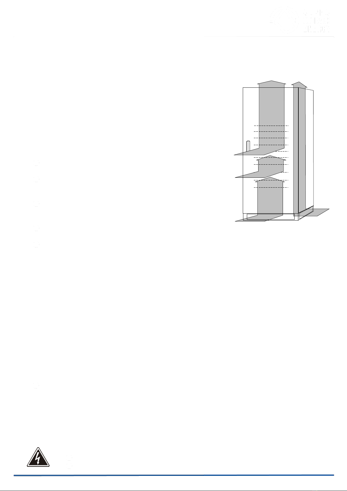
2.2 Dimensions of the premises ............................................................................................................................... 8
2.3 Cooling of the premises ...................................................................................................................................... 9
2.4 Air change for battery premises ......................................................................................................................... 9
3. TRI POWER X33 HIP IN SINGLE CONFIGURATION ......................................................................................... 10
3.1 Set-up of the electrical system ......................................................................................................................... 10
3.1.1
Input ............................................................................................................................................................... 10
3.1.2
Selectivity ....................................................................................................................................................... 11
3.1.3
Battery ............................................................................................................................................................ 12
3.1.4
neutral conductor ........................................................................................................................................... 12
3.1.5
Differential (RCD) ........................................................................................................................................... 13
3.1.6
Backfeed protection ....................................................................................................................................... 14
3.1.7
Emergency power off device (EPO) .............................................................................................................. 14
3.2 Mains, load and battery connections ................................................................................................................ 15
3.3 Connection of signals and remote commands ................................................................................................. 17
3.3.1
EPO connector (emergency power off control).............................................................................................. 17
3.3.2
REMOTE COMMANDS AND ALARMS ......................................................................................................... 17
3.3.3
RS232 ............................................................................................................................................................ 18
3.3.4
Parallel (optional) ........................................................................................................................................... 19
3.3.5
SLOTS 2-1 ..................................................................................................................................................... 19
3.3.6
REMOTE ALARMS (2 optional cards) ........................................................................................................... 19
3.3.7
MODEM (optional) ......................................................................................................................................... 19
3.3.8
MULTI I / O (optional) .................................................................................................................................. 20
3.3.9
REMOTE PANEL (OPTIONAL) ..................................................................................................................... 20
3.3.10
Dual Bus System – UGS (optional). .............................................................................................................. 20
3.3.11
SWOUT and SWMB aux - External temperature sensor (optional). .............................................................. 21
3.4 Start-up procedure ............................................................................................................................................ 24
3.4.1
Battery operation check ................................................................................................................................. 25
3.5 Operating modes .............................................................................................................................................. 26
3.5.1
On - line - factory setting ................................................................................................................................ 26
3.5.2
Standby-on / Smart active .............................................................................................................................. 26
3.5.3
Standby-off (with mains present the load is not powered) ............................................................................. 27
3.5.4
Stabilizer (operation in on-line mode without battery) ................................................................................... 27
3.5.5
Frequency converter (from 50 to 60Hz or vice versa) ................................................................................... 27
3.6 Personalizations ............................................................................................................................................... 28
3.7 Procedure to transfer the load from UPS onto maintenance bypass. .............................................................. 28
3.8 UPS and load shutdown ................................................................................................................................... 29
3.9 Block diagram ................................................................................................................................................... 30
3.10 Components of the block diagrams .................................................................................................................. 31
4. TRI POWER X33 HIP IN PARALLEL CONFIGURATION ................................................................................... 34
4.1 Introduction ....................................................................................................................................................... 34
4.2 Electrical system set-up .................................................................................................................................... 35
4.2.1
Input ............................................................................................................................................................... 35
4.2.2
Differential ...................................................................................................................................................... 35
4.2.3
Emergency power off device (EPO) .............................................................................................................. 35
4.2.4
External maintenance bypass ........................................................................................................................ 36
Page 5 to 54