Alpha A1-14-24-P Installation and operating instructions

Alpha™
Level 2 Interactive
Home EV Charging Station
User Manual & Installation Guide

Manual Revision 1.0
April 27, 2023
Table of Contents
INTRODUCTION .......................................................................................................................1
Product Specications............................................................................................................. 1
Important Safety Instructions ................................................................................................ 2
General Product Care and Use Information......................................................................... 2
Alpha Level 2 EV Charger Overview....................................................................................... 3
INSTALLATION.........................................................................................................................4
Service Wiring Requirements ................................................................................................ 4
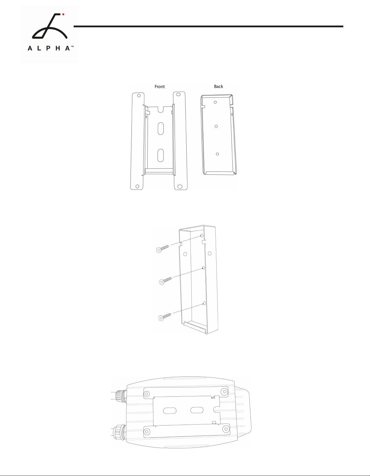
Install Charging Station ........................................................................................................... 5
Adjust Maximum Output Current DIP Switches................................................................... 8
Optional Hardwire Connection .............................................................................................. 10
Install EasyEVPlug .................................................................................................................... 11
OPPERATION............................................................................................................................12
Indicator Light .......................................................................................................................... 12
Connect and Charge................................................................................................................ 13
Stop Charging........................................................................................................................... 13
Lock Screen............................................................................................................................... 14
Home Screen............................................................................................................................ 14
Charger Fault ........................................................................................................................... 15
SMART CHARGING FEATURES.................................................................................................16
Users ......................................................................................................................................... 16
Charging Schedule................................................................................................................... 17
Energy Meter ............................................................................................................................ 18
Reports...................................................................................................................................... 18
Maximum Amperage............................................................................................................... 19
Set Date and Time ................................................................................................................... 20
Version Info .............................................................................................................................. 20
SETTINGS ..................................................................................................................................21
Wi-Fi .......................................................................................................................................... 21
OCPP Connections .................................................................................................................. 21
USB Firmware Update ............................................................................................................ 21
Ethernet ................................................................................................................................... 21
Volume ...................................................................................................................................... 21
Camera...................................................................................................................................... 21
Delete Users & Reset............................................................................................................... 21
Brightness ................................................................................................................................ 22
Warranty Info ........................................................................................................................... 22
Language .................................................................................................................................. 22
Themes...................................................................................................................................... 23
USB SOFTWARE UPDATE .........................................................................................................24
WARRANTY...............................................................................................................................25
Model Number A1-14-24-P
A1-6-24-P
EVSE Level Level 2
Maximum Output Rating 40Amps (9.6kW)
Alternate Adjustable Output Ratings 32A; 7.68 kW – For use with 40A Circuit Rating
24A; 5.76 kW – For use with 30A Circuit Rating
16A; 3.84 kW – For use with 20A Circuit Rating
Charge Cable Length 24ft (7.3m)
Electrical Circuit / Input Power
Requirements
Circuit Requirement: Dedicated Single Phase 208-
240VAC, 50/60 Hz. Branch Breaker: Double pole.
Circuit Conductors: Line 1, Line 2, Earth / Ground.
Input Power Connection Standard: Plug-in NEMA 6-50 or NEMA 14-50 Plug.
Plug is removable for Hardwire Connection.
Installation Rating: NEMA 3R, Indoor/Outdoor Rated.
Operational Ratings:Temperature: -22⁰F to 122⁰F (-30⁰C to 50⁰C); Humidity: 95% RH
noncondensing
Mounting: Wall Mounted
Overall Dimensions EVSE: 10.25 x 6.25 x 3.75 inches (26.0 x 16.0 x 9.3
cm)
Display and Indicators 7-inch touch screen interactive display
LED Indicator Light

1
INTRODUCTION
Product Specications
Alpha is an interactive, touch-screen Level 2 EV Charger. The 7-inch touch-screen color display
gives you direct interaction with the charger to control settings, monitor real-time charging,
create a charging schedule, set maximum power, and more.
The 25ft (7.62M) output cable is compatible with all J1772 Electric Vehicles. Alpha provides up to
10 KW of power to your vehicle and can be adjusted for 16A-40A Maximum Current Output.
Model Number A1-14-24-P
A1-6-24-P
EVSE Level Level 2
Maximum Output Rating 40Amps (9.6kW)
Alternate Adjustable Output Ratings 32A; 7.68 kW – For use with 40A Circuit Rating
24A; 5.76 kW – For use with 30A Circuit Rating
16A; 3.84 kW – For use with 20A Circuit Rating
Charge Cable Length 24ft (7.3m)
Electrical Circuit / Input Power
Requirements
Circuit Requirement: Dedicated Single Phase 208-
240VAC, 50/60 Hz. Branch Breaker: Double pole.
Circuit Conductors: Line 1, Line 2, Earth / Ground.
Input Power Connection Standard: Plug-in NEMA 6-50 or NEMA 14-50 Plug.
Plug is removable for Hardwire Connection.
Installation Rating: NEMA 3R, Indoor/Outdoor Rated.
Operational Ratings:Temperature: -22⁰F to 122⁰F (-30⁰C to 50⁰C); Humidity: 95% RH
noncondensing
Mounting: Wall Mounted
Overall Dimensions EVSE: 10.25 x 6.25 x 3.75 inches (26.0 x 16.0 x 9.3
cm)
Display and Indicators 7-inch touch screen interactive display
LED Indicator Light

2
Important Safety Instructions
This User Guide contains instructions and warnings that must be followed when installing and
using the Alpha Electric Vehicle Supply Equipment (EVSE). Before installing or using the EVSE,
read this document including any WARNING and CAUTION markers.
This document provides instructions for the charging station and should not be used for any
other product. Consult with a licensed contractor, licensed electrician, or trained installation
expert to ensure compliance with local building codes and safety standards.
• Read all the instructions before using this product.
• Before installation or use of this product consult with a licensed electrician to ensure
compliance with local building codes and safety standards.
• Children should not use this device.
• Do not put ngers into the EV connector.
• Do not touch live electrical parts.
• Do not use this product if the exible power cord, EV cable, or enclosure is ragged, broken,
cracked, open, or shows any other indication of damage.
• Disconnect the power supply before installing, adjusting, or repairing the charging station.
General Product Care and Use Information
• The Alpha EVSE does not require regular maintenance. Inspect the unit periodically to ensure
that all parts remain in good working order and no damage exists.
• Do not attempt to disassemble, repair, tamper with, or modify any components inside the
device. Contact United Chargers for any repairs.
The exterior of the charging station is water-resistant (NEMA 3R Indoor/Outdoor Rated).
To ensure proper maintenance of the charging station, follow these guidelines:
• Periodic cleaning may be required, depending on local conditions. Only use an automotive
grade soft cleaning cloth damp with soap and water to remove accumulated dirt and dust. Do
not use cleaning solvents.
• Ensure the charging connector is put back in the holster and the power cable is stored on the
charging station after use to avoid damage.
• When moving or lifting the unit, always grasp and carry by the charging station body. Never
attempt to lift, move, or carry the unit by any of the electrical cables.

3
Alpha Level 2 EV Charger Overview
1
2
3
4
5
1. Status Indicator Light
2. Touch Screen Interface
3. Input Plug: NEMA 14-50 or
NEMA 06-50
4. Latch Release Button
5. J1772 Output Cable

4
INSTALLATION
Service Wiring Requirements
Prior to mounting, consult a certied electrician about an electrical source that can support the
following:
The Circuit must be a DEDICATED CIRCUIT 208-240 VAC, 50-60 Hz, Single Phase.
Requirements govern that only 80% of the circuit rated load may be utilized. Use the following
Maximum Amperage Settings depending on the circuit breaker rating:
Circuit Rating Maximum Charging Station Output
50A 40A
40A 32A
30A 24A
20A 16A
• A Double Pole Circuit Breaker of the circuit rating must be used.
• The Charging Stations can connect a Standard NEMA 6-50 or 14-50 Receptacle, or the unit can
be hardwired.
• A cable with a dedicated grounding conductor connected to the equipment ground terminal
block must be used.
CAUTION: The service wiring in this section are specic to North America only. Before installing
the Charging Station, identify the type of utility service connection onsite. If unsure about the
type of connection available at the service panel, contact your utility service provider.
WARNING: Disconnect the power supply to the charging station before installing, adjusting, or
repairing the charging. Failure to do so may result in physical injury or damage to the power
supply system and the charging station.

5
Install Charging Station
Prior to mounting, determine the location of an acceptable mounting support:
• The charging station must be anchored into a mounting support such as a 2” x 4” stud or a
solid concrete wall. DO NOT mount this unit directly to a stucco/drywall/wall board.
• Mount the unit between 24 inches (0.6 m) and 48 inches (1.2 m) from the ground. The NEMA
outlet should be located more than 18” above the ground or as dened by applicable, local
electrical safety codes and standards.
Mounting Screw Recommendations:
• For nished walls supported by wood studs, use #14 or M6 tapping screws. (Included).
• For masonry walls, use M6 mechanical screws. (Commercially available)
Parts and Tools required for installation:
Part Size Source
Mounting Bracket 255 x148 x 36 mm Included with product
Robertson-Head Screw (x2) #14 Included with product
Socket cap screw (x4) 5/16” Included with product
Side Bracket Included with product
Side Cover Screws 40mm Included with product
Allen Key 3/16” Commercially Available
Robertson Head Screwdriver #14 Commercially Available

6
1. Separate the front and back pieces of the mounting bracket by pushing down on the notch.
2. Secure the back piece of the mounting bracket to the wall or other suitable structure using the
Robertson-head screws.
3. Attach the front piece of the mounting bracket to the back of the charging station using the
Socket-cap screws and washers. Ensure the top of the mounting bracket is matched with the top
of the charging station.

7
4. Mount the charger on the wall by securing the front piece of the mounting bracket to the back
piece. Align the notches and press down to secure the charger.
5. Position the Side Cover over the mounting bracket. Use the Side Cover screws to secure the
two pieces together.
6. Plug in the power cord to the NEMA 14-50 or NEMA 6-50 Wall Outlet/Receptacle.

8
Adjust Maximum Output Current DIP Switches
Note: Only change the Maximum Current DIP Switch settings if your local electrical code
requires a physical switch for compliance. If the building code does not require a physical switch
use see “Set Amperage” on page 19.
To set the Maximum Output Current through the DIP Switches:
1. Ensure the unit is unplugged. Ensure Charging Station is facing up on a at surface.
Remove the plastic protective cover.
2. Use a Phillips Head screwdriver to remove the 6 screws on the front of Alpha. Carefully place
the front cover to the side without damaging the communication cable.
3. Locate the DIP Switches on the PCB. The DIP Switch is a 3-position switch on the secondary
circuit board, located behind the USB cable.

9
4. Remove protective cover from DIP Switches
5. Use the following combination of switch settings to adjust the maximum current:
40A Maximum Current
(Factory Default Setting)
32A Maximum Current
24A Maximum Current
16A Maximum Current
Switch
1 2 3
Maximum Current
Setting

10
Optional Hardwire Connection
CAUTION: Do Not attempt to hardwire the Alpha unless you are qualied to do so. If you are not
qualied, contact a licensed electrician.
1. Choose a copper wire conduit in accordance with all applicable, local, and electrical safety
codes and standards.
2. Choose a terminal ring with the following characteristics:
• Recommended Wire Strip length: 8mm (0.32”)
• Width of the terminal block opening: 10.2mm (0.41”)
3. Using the appropriate tool, clamp the wire terminal to the copper wire. For non-insulated
terminals, use a heat shrink tube to cover the non-insulated portion of the terminal.
4. Remove the plastic protective cover from the front of Alpha.
5. Use a Phillips Head screwdriver to remove the 6 screws on the front of alpha. Carefully place
the front cover to the side without damaging the communication cable.
6. With the front cover placed to the side, use a Philips Head screwdriver to release terminal
screws of the 6-50 or 14-50 Plug cable. Loosen the Strain Relief Fitting and remove the Plug.
Remove the Strain Relief connector.
7. Insert the wire end passing through the conduit and insert them into the input wiring hole.
(Use Red wire for L1, Black wire for L2, Green wire for G). Attach the wire terminal to the
corresponding terminal block. Use the following wire and torque force when connecting to
input terminal block:
Terminal Conductor Screw Rating Torque
L1 8 AWG M4 75C copper wire max 1.8Nm | 16
LBF.IN
L2 8 AWG M4 75C copper wire max 1.8Nm | 16
LBF.IN
G8-10 AWG M4 75C copper wire max 1.8Nm | 16
LBF.IN

11
Install EasyEVPlug
The EasyEVPlug™ Holster or Tesla EasyEVPlug™ Holster is the new innovative method to protect
your plug and manage your cord. It has the following features:
• No need to aim – awless plug even in the dark.
• Your EV holster will always be in a convenient location.
• Saves space – special angle for less wall clearance.
• Integrated cable management – holds up to 25 feet of cable.
The EasyEvPlug holster can be installed at any location near the charging station.
1. Hold back of holster against the mounting surface.
Fasten Phillips head screws through back holes. Use
anchors if attaching directly to drywall. (x4)
2. Insert charging connector into holster.
3. Wrap cable on top of EasyEvPlug.

12
OPPERATION
Indicator Light
The Indicator Light is located at the top right corner of the screen. Alpha uses the following
indicator lights for the charger status:
Indicator Light Description Denition
Yellow Steady Initialization
Cyan Flashing Update in Progress
Blue Steady Ready
Blue Flashing Vehicle Detected
Green Flashing Charging in Progress
Green Steady Charging Complete
Red Flashing Fault (See “Charger Fault” on
page 15)

13
Indicator Light Description Denition
Yellow Steady Initialization
Cyan Flashing Update in Progress
Blue Steady Ready
Blue Flashing Vehicle Detected
Green Flashing Charging in Progress
Green Steady Charging Complete
Red Flashing Fault (See “Charger Fault” on
page 15)
Connect and Charge
1. Insert the J1227 charging Connector into the EV and ensure the connector is fully seated/
locked in place.
2. Select the Start Now button from the charging screen.
Stop Charging
1. Press down on the latch release button. Ensure latch release button is fully compressed.
2. Remove the Charger Connector from the EV
3. Return the connector to the holster.

14
Lock Screen
The lock screen is the rst screen you will encounter.
Select the Touch to Unlock button to enter to the Home
Screen.
If a PIN Code has been set the charger will prompt the
user to enter the PIN Code. For more information on
setting a PIN see “Users” on page 16.
Home Screen
All functions of Alpha can be accessed through the
Home Screen.
Touch an icon to access the function.
Select the Home button to go back to the Home
Screen at any time.

15
Charger Fault
When the Charger experiences a fault the indicator light
will ash red, and the error screen will display.
Reset Charger
In the instance of a fault, it is recommended that you
perform a reset:
1. Unplug the charging Connector from your EV.
2. Power off the Charging Station by unplugging it or
switching the upstream circuit breaker to the “OFF”
position.
3. Wait 1-2 minutes and then power the charger back
on.
4. Confirm the Fault light is no longer present.
Fault Codes
The indicator light will flash, and the buzzer will sound when the unit is in fault mode.
The number of red flashes indicates the type of fault:
LED Indicator # of Flashes Error Description
Red Flashing 1Lost ground - AC Line1
Red Flashing 2GFCI High Leakage
Red Flashing 3Relay is stuck
Red Flashing 4GFCI Low Leakage
Red Flashing 5High temperature of the module
Red Flashing 6High temperature of the relay-
Red Flashing 7Pilot state is Status E
Red Flashing 8Pilot state is Status F
Red Flashing 9Diode error
Red Flashing 10 Over Current
Red Flashing 12 Application Error
If fault remains contact United Chargers technical support. Include the fault error code and
number of red flashes.
https://autochargers.zendesk.com/hc/en-ca

16
SMART CHARGING FEATURES
Users
Only accessible by Master User
The Users screen allows you to set multiple proles with
PIN code access.
Master user is the default. Two additional users can be
added. Master does not have any PIN code by default.
Set Users:
1. Select the User icon from the main menu.
2. Enter a User ID for Master, User 1, or User 2.
3. Enter a PIN Code for Master, User 1, or User 2.
4. Select the Home button to go back to the main
menu. Your settings will be saved.
Lock Charger:
Select the Lock button on the home screen.
The charger will display the lock screen. Once locked the
charger will require the PIN code to access.
Login as a User:
Entered the PIN Code created for the user. The charger
will login as that user.
Always make sure to Lock the charger after use.

17
Charging Schedule
Only accessible by Master User.
Set Charging Schedule
1. Select the Schedule icon from the home
screen.
2. Use the arrows to adjust the hour and minute of the
Start Time. Select AM or PM. Charging will start at
the specied time stop at the specied time.
3. Set the On/O toggle to ON.
4. Press the Set button. Note: Set the schedule in both
weekdays and weekends to use both.
5. Select the Home button to go back to the main
menu. Your settings will be saved.
Override Charging Schedule
1. Connect J1772 connector to the vehicle.
2. Select Charge Now or Ignore Schedule from the
charging screen.
Start Now: The charging session will begin immediately
and end at the scheduled time.
Ignore Schedule: The charging session will begin
immediately and ignore the scheduled stop time for 1
complete charging session.

18
Energy Meter
1. Select the Energy Meter icon from the main
menu.
2. The Energy Meter screen will display the following
power consumption statistics:
• Charging Time
• Output Voltage
• Output Current
• Power
Power Consumption statistics from the last charging
session. If a charging session is in progress, it will display
real-time Power Consumption statistics.
Reports
1. Select the Report icon from the main screen.
2. Select the user Master, User1, or User2.
3. Use the arrows to select the last two digits of the
Year and Month.
4. Select the Read button.
5. The report screen will display the total session time
and Total kWh used from that session.
Other manuals for A1-14-24-P
1
This manual suits for next models
1
Table of contents