Alpha SMG-00LI-01 User manual

1018-354-B1-001, Rev. A (05/2018)
AlphaGateway SMG-00LI-01 Quick Start Guide
The SMG-00LI-01 is a strand-mounted HFC-powered, DOCSIS 3.0 LoRaWAN Gateway that utilizes the power, backhaul
and real-estate of the Broadband Access Network’s aerial coax network to enable LoRaWAN communications.
This device complies with part 15 of the FCC Rules. Operation is subject to the following two conditions: (1) This device
may not cause harmful interference, and (2) this device must accept any interference received, including interference that
may cause undesired operation.
This product has been inspected by regulatory for use as described in the manual. If your intended use is dierent, it
is your responsibility to ensure your combination conforms to your local regulatory requirements and the Power Supply
remains within its environmental specications.
ATTENTION:
4
1
2
3
5
6
7
8
6
6
6
Contains FCC ID: 2ALEPT0004564
9
1. AlphaGateway SMG-00LI-01, Vertical Orientation (PN: 018-354-20-001)
2. Active GPS Antenna (PN: 670-025-19)
3. LoRaWAN Antenna Ports
4. Coaxial F Connector Port (provides power to the SMG via power passing tap)
5. Status LEDs (located on bottom of unit)
6. Strand Mount Brackets (PN: 746-627-23-001)
7. Ground Lug Connection
8. 2-in-1 Combo Antenna, CH2P900 (PN: 670-024-19)
9. LoRa Antenna Cables, 50” (PN: 876-275-19), 75” (PN: 876-274-19)
4
1
2
3
5
6
7
8
9

2018-354-B1-001, Rev. A (05/2018)
SMG-00LI congurations:
• SMG-00LI-01-00SL with 3” Strand Brackets, Vertical Orientation (PN: 018-354-20-001)
• SMG-00LI-01-00S2 with 2” Strand Brackets, Horizontal Orientation (PN: 018-354-22-001)
Bracket Kits:
• 3” Strand Mount Bracket Kit for Vertical Orientation (PN: 746-627-23-001)
• 2” Strand Mount Bracket Kit for Horizontal Orientation (PN: 746-627-30-001) includes:
• 2” Strand Mount Bracket Kit for SMG-00LI (PN: 746-627-22-001)
• 2” Strand Mount Bracket Kit for 2-in-1 Combo Antenna (PN: 746-627-24-001)
• Right-Angle Adaptor for GPS Antenna, Horizontal Orientation (PN: 659-014-10)
Antenna Kits:
• External Dipole Antenna Kit (PN: 746-627-41-001) includes:
• (2) External Dipole Antenna ET915NJMR (PN: 670-016-19)
• (1) Antenna Cable 50” (PN: 876-275-19)
• (1) Antenna Cable 75” (PN: 876-274-19)
• (2) Strand Mount Bracket Kit for External Dipole Antenna (PN: 746-627-31-001)
• 2-in-1 Combo Antenna Kit (PN: 746-627-40-001) includes:
• (1) 2-in-1 Combo Antenna CH2P900 (PN: 670-024-19)
• (1) Antenna Cable 50” (PN: 876-275-19)
• (1) Antenna Cable 75” (PN: 876-274-19)
A vertical SMG-00LI installation congured with the 2-in-1 Combo Antenna requires two sets of the 3” Strand Mount
Bracket Kits (PN: 746-627-23-001).
NOTICE:

3018-354-B1-001, Rev. A (05/2018)
Pre-Installation
Prior to Installation:
• Provision the SMG’s DOCSIS Modem and RF MAC Address. This can include, but is not limited to:
• Assign a cable modem conguration le with the CPE enabled, and the bandwidth set properly.
• Set up a billing account (if applicable)
• Install a power-passing tap on the hard coax.
Required Tools and Materials (User-Supplied):
• Torque Wrench
• 3/8” (10mm) Socket
• 1/2” (13mm) Socket
• 13/16” (21mm) Open-End Wrench
Standard Installation
1. Using the hex head bolts, lock washers, and at washers, secure the strand brackets (PN: 746-627-23-001) to the
SMG (PN: 018-354-20-001), torquing to 44.3 – 53.1 in-lbs (5 – 6 N-m). Verify proper orientation as shown in the
image below.
Hex head bolt
Flat washer
Lock washer
Bracket
SMG
Main enclosure bolts are required to be torqued to 44.3 – 53.1 in-lbs (5 – 6 N-m).
NOTICE:

4018-354-B1-001, Rev. A (05/2018)
2. Hang both brackets on the strand through the clamps on the bracket as shown. For thicker 3/8” strands, reverse
the orientation of the clamp so that the larger concave side faces the strand. Insert the carriage bolt through the
back of the bracket and tighten the hex head nut, lock washer, and at washer against the clamp on the front of
the bracket, torquing to 79.7 – 88.5 in-lbs (9 – 10 N-m). Repeat for the second bracket.
3. Using the hex head bolts, lock washers, and at washers, secure the strand brackets to the dual antenna module,
torquing to 44.3 – 53.1 in-lbs (5 – 6 N-m).
Bracket
Strand
Carriage bolt
Hex head nut
Lock washer
Flat washer
Clamp
Hex head bolt
Flat washer
Lock washer
Bracket
Antenna

5018-354-B1-001, Rev. A (05/2018)
4. Hang the antenna on the strand about 36” from the ports on the side of the SMG. For thicker 3/8” strands, reverse
the orientation of the clamp so that the larger concave side faces the strand. Insert the carriage bolt through the
back of the bracket and tighten the hex head nut, lock washer, and at washer against the clamp on the front of
the bracket, torquing to 79.7 – 88.5 in-lbs (9 – 10 N-m). Repeat for the second bracket.
5. Attach the antenna cables to the SMG Antenna ports on one end and to the antenna housing on the other. Torque
connectors to 15 – 20 in-lbs (1.7 – 2.3 N-m).
6. Properly ground the SMG by connecting a #6 AWG wire from the grounding lug on the outside of the enclosure
to either a driven ground rod or the strand ground on the pole to which the unit is mounted. Apply anti-oxidant
compound (e.g. Noalox® or equivalent) to the ground connection. Torque to 44.3 in-lbs (5 N-m).
7. Proceed to the “Start-Up and Verication” section.
Ground Lug
Connection
36”

6018-354-B1-001, Rev. A (05/2018)
Horizontal Installation
1. Attach the GPS Antenna (PN: 670-025-19) to the SMG (PN: 018-354-22-001) using a 13/16” wrench and the
included right angle adapter (PN: 659-014-10) as shown in the image below. Torque to 15 in-lbs (1.7 N-m).
2. Using the hex head bolts, lock washers, and at washers, secure the strand brackets (PN: 746-627-22-001) to the
SMG, torquing to 44.3 – 53.1 in-lbs (5 – 6 N-m). Verify proper orientation as shown in the image below.
3. Hang both brackets on the strand through the clamps on the bracket as shown. For thicker 3/8” strands, reverse
the orientation of the clamp so that the larger concave side faces the strand. Insert the carriage bolt through the
back of the bracket and tighten the hex head nut, lock washer, and at washer against the clamp on the front of
the bracket, torquing to 79.7 – 88.5 in-lbs (9 – 10 N-m). Repeat for the second bracket.

7018-354-B1-001, Rev. A (05/2018)
4. Using the hex head bolts, lock washers, and at washers, secure the strand brackets (PN: 746-627-24-001) to the
dual antenna module, torquing to 44.3 – 53.1 in-lbs (5 – 6 N-m).
5. Hang the antenna on the strand about 36” from the ports on the side of the SMG. For thicker 3/8” strands, reverse
the orientation of the clamp so that the larger concave side faces the strand. Insert the carriage bolt through the
back of the bracket and tighten the hex head nut, lock washer, and at washer against the clamp on the front of
the bracket, torquing to 79.7 – 88.5 in-lbs (9 – 10 N-m). Repeat for the second bracket.
6. Attach the antenna cables to the SMG Antenna ports on one end and to the antenna housing on the other. Torque
connectors to 15 – 20 in-lbs (1.7 – 2.3 N-m).
7. Properly ground the SMG by connecting a #6 AWG wire from the grounding lug on the outside of the enclosure
to either a driven ground rod or the strand ground on the pole to which the unit is mounted. Apply anti-oxidant
compound (e.g. Noalox® or equivalent) to the ground connection. Torque to 44.3 in-lbs (5 N-m).
8. Proceed to the “Start-Up and Verication” section.

8018-354-B1-001, Rev. A (05/2018)
3. With each antenna secured, hang the brackets on the strand at about 36” and 60” away from the ports on the side
of the SMG. For thicker 3/8” strands, reverse the orientation of the clamp so that the larger concave side faces the
strand. Insert the carriage bolt through the bottom of the bracket and tighten the hex head nut, lock washer, and
at washer against the clamp on the top of the bracket, torquing to 79.7 – 88.5 in-lbs (9 – 10 N-m). Repeat for the
second bracket.
4. Attach the antenna cables to the SMG Antenna ports on one end and to each antenna on the other. Torque
connectors to 15 – 20 in-lbs (1.7 – 2.3 N-m).
5. Properly ground the SMG by connecting a #6 AWG wire from the grounding lug on the outside of the enclosure
to either a driven ground rod or the strand ground on the pole to which the unit is mounted. Apply anti-oxidant
compound (e.g. Noalox® or equivalent) to the ground connection. Torque to 44.3 in-lbs (5 N-m).
6. Proceed to the “Start-Up and Verication” section.
External Dipole Antenna Installation
1. Follow the standard installation steps 1 and 2 for hanging the SMG on the strand.
2. Attach each external dipole antenna to a strand mount bracket (PN: 746-627-31-001) using the included
hardware, as shown below. Torque to 79.7 – 88.5 in-lbs (9 – 10 N-m).
Hex head nut
Lock washer
Flat washer
Hex head bolt

9018-354-B1-001, Rev. A (05/2018)
Start-Up and Verification
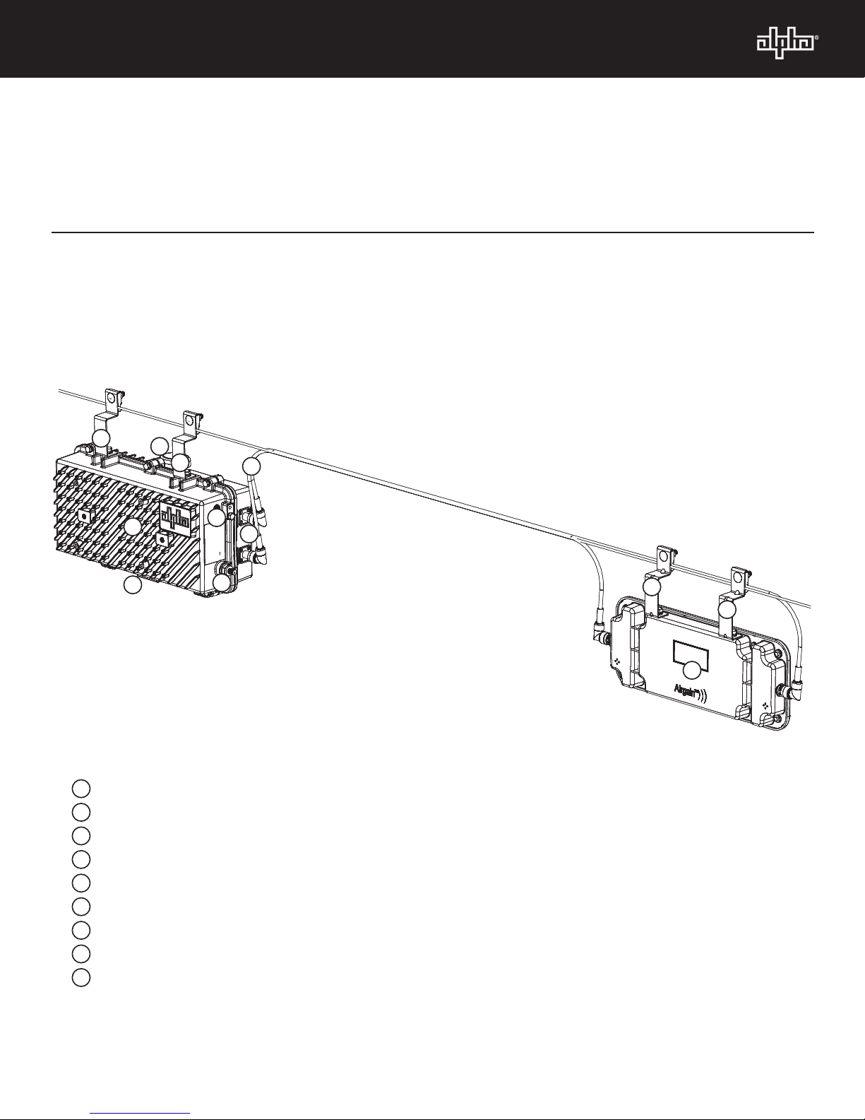
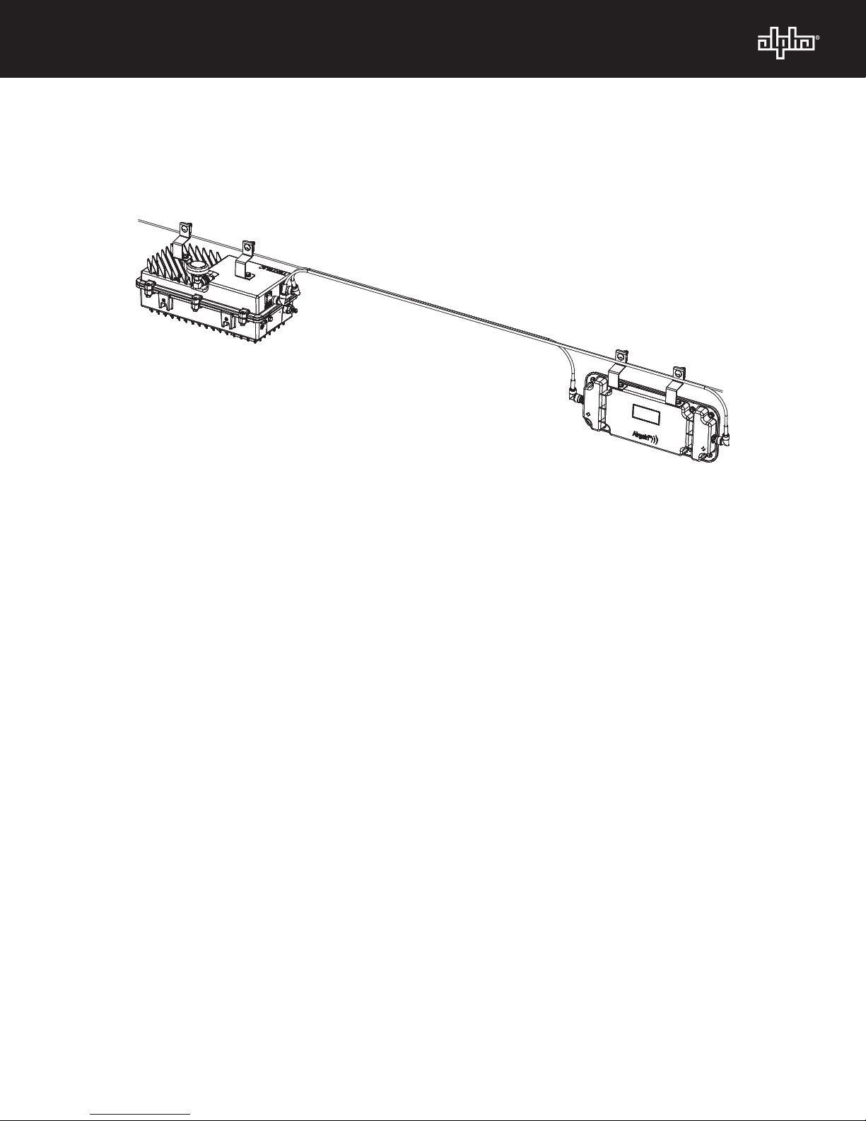
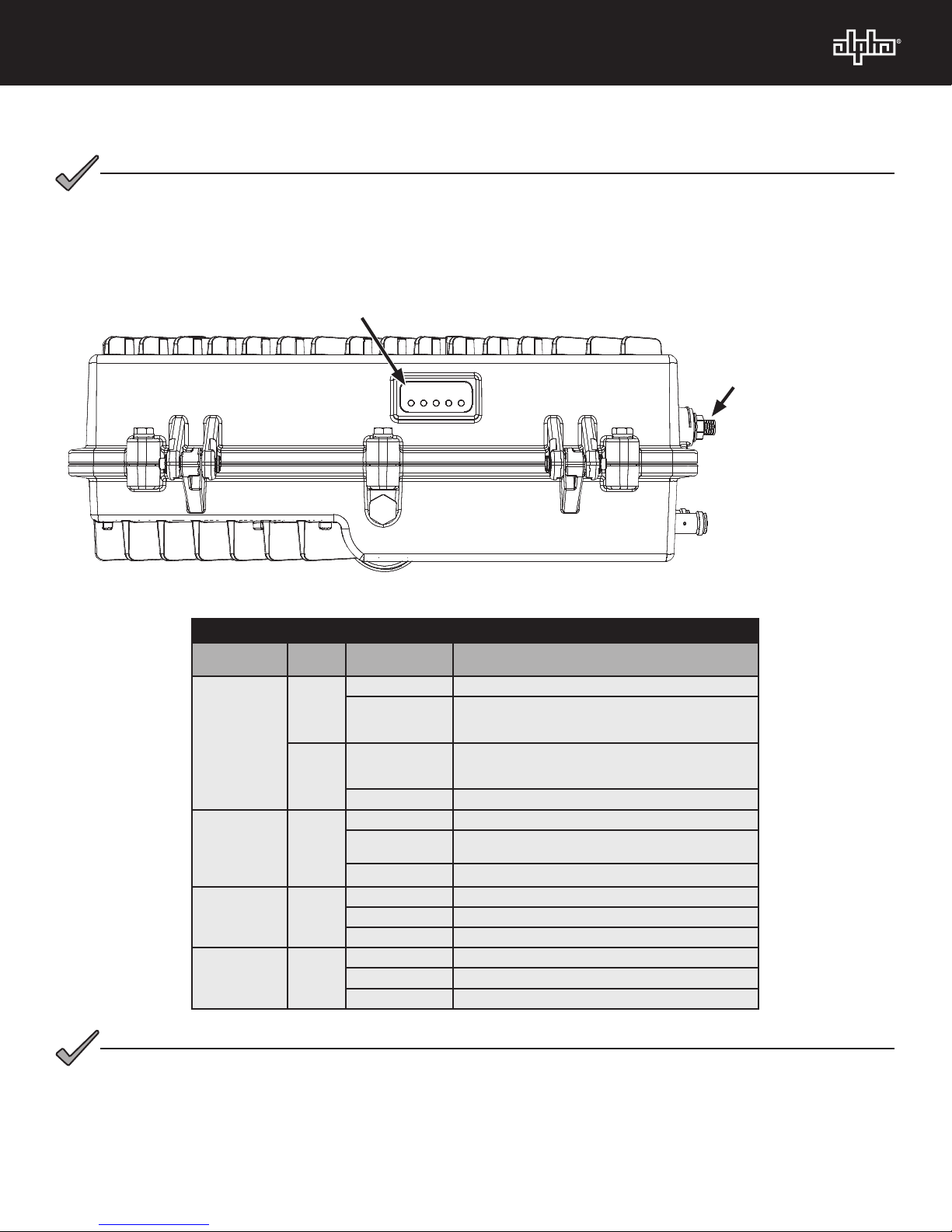
1. Connect the powered-coax from the coaxial F connector port to the power-passing tap. When installing the coax
to the F Connector, torque to 35 in-lbs (4.0 N-m).
2. Verify that the unit powers up by looking at the DOCSIS Modem “POWER” LED.
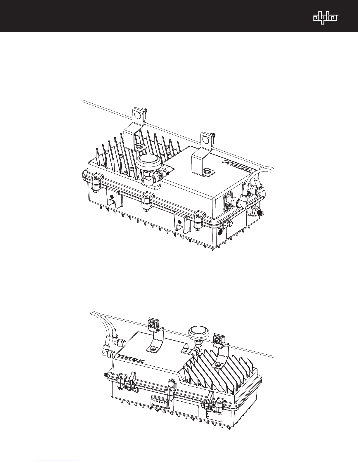
Coaxial F Connector
Port (Provides power
to the SMG via a
power passing tap as
well as data backhaul
and status monitoring
to the HFC network)
Status LEDs
DS
US
ONLINE
LoRa
RF levels at the power-passing tap need to be balanced according to WiFi HFC Plant RF Design Specications.
NOTICE:
Status LEDs and Indications
LED or
Connector Status Behavior Indication
LoRa
GREEN
OFF / ON Module is initializing
ON
Module is operational with an application (e.g. Packet
forwarder) running. LoRaWAN uplink and downlink packets
are supported.
RED OFF / ON
Failure related to interfaces - technician to check
connections, run interface Built in Self Tests (BIST), check
software versions and upgrade if required.
ON Unit is in fault condition and requires service
ONLINE:
(Online status) GREEN
OFF No Communications Activity
OFF / ON Flashes while performing early authentication, IP
connectivity, BPI intialization.
ON Online and Operational
US: Upstream
ranging and
registration lock
GREEN
OFF No power, upstream frequency undetermined
OFF / ON Power on, downstream locked, upstream frequency ranging
ON Initial CM ranging completed
DS: Downstream
RF Carrier
detection and
lock
GREEN
OFF No Power / Downstream Carrier
OFF / ON Power on, downstream carrier frequency searching
ON Downstream carrier lock
For LoRaWAN operational details refer to the SMG-00LI-01 Technical Manual (PN: 018-354-B0-001).
NOTICE:

Alpha Technologies Alpha reserves the right to change specications without notice.
Alpha is a registered trademark of Alpha Technologies.
For more information visit www.alpha.com
© 2018 Alpha Technologies Inc. All Rights Reserved.
018-354-B1-001, Rev. A (05/2018)
Worldwide Corporate Oces
North America
Tel: +1 360 647 2360
Fax: +1 360 671 4936
Europe
Tel: +49 9122 79889 0
Fax: +49 9122 79889 21
Latin America
Tel: +561 792.9651
Fax: +561 792.7157
Asia Pacic
Tel: +852 2736.8663
Fax: +852 2199.7988
Other manuals for SMG-00LI-01
1
Table of contents
Other Alpha Gateway manuals