Alpha DCX Series User manual

DCX™Series
Top Terminal Battery Disconnect System
Installation and Operation Manual
Effective: January 2021

2C048-699-30 R03, Rev. B (01/2021)
The following sections contain important safety information that must be followed during the installation and maintenance
of the equipment and batteries. Read all of the instructions before installing or operating the equipment, and save this
manual for future reference.
There may be multiple warnings associated with the call out. Example:
ATTENTION provides specic regulatory/code requirements that may aect the placement of equipment and /or
installation procedures.
ATTENTION:
NOTICE provides additional information to help complete a specic task or procedure.
NOTICE:
ELECTRICAL HAZARD WARNING provides electrical safety information to PREVENT INJURY OR DEATH
to the technician or user.
WARNING! ELECTRICAL HAZARD
FUMES HAZARD WARNING provides fumes safety information to PREVENT INJURY OR DEATH to the
technician or user.
WARNING! FUMES HAZARD
FIRE HAZARD WARNING provides ammability safety information to PREVENT INJURY OR DEATH to the
technician or user.
WARNING! FIRE HAZARD
This WARNING provides safety information for both Electrical AND Fire Hazards
WARNING! ELECTRICAL & FIRE HAZARD
CAUTION provides safety information intended to PREVENT DAMAGE to material or equipment.
CAUTION!
GENERAL HAZARD WARNING provides safety information to PREVENT INJURY OR DEATH to the
technician or user.
WARNING! GENERAL HAZARD
Safety Notes
Alpha Technologies Services, Inc. considers customer safety and satisfaction its most important priority. To reduce the
risk of injury or death and to ensure continual safe operation of this product, certain information is presented dierently in
this manual. Alpha®tries to adhere to ANSI Z535 and encourages special attention and care to information presented in
the following manner:

3C048-699-30 R03, Rev. B (01/2021)
DCX™ Series
Top Terminal Battery Disconnect System
Installation and Operation Manual
C048-699-30 R03, Rev. B
Eective: January 2021
© 2021 by Alpha Technologies Services, Inc.
Disclaimer
Images contained in this manual are for illustrative purposes only. These images may not match your installation.
Operator is cautioned to review the drawings and illustrations contained in this manual before proceeding. If there are
questions regarding the safe operation of this powering system, please contact Alpha Technologies Services, Inc. or your
nearest Alpha representative.
Alpha® shall not be held liable for any damage or injury involving its enclosures, power supplies, generators, batteries or
other hardware if used or operated in any manner or subject to any condition not consistent with its intended purpose or is
installed or operated in an unapproved manner or improperly maintained.
Contact Information
Sales information and customer service in USA
(7AM to 5PM, Pacic Time): 1 800 322 5742
Complete Technical Support in USA
(7AM to 5PM, Pacic Time or 24/7 emergency support): 1 800 863 3364
Sales information and Technical Support in Canada: 1 888 462 7487
Website: www.alpha.com

4C048-699-30 R03, Rev. B (01/2021)
Contents
1.0 Purpose and Applicability . . . . . . . . . . . . . . . . . . . . . . . . . . . . . . . . . . . . . . . . . . . . . . . . . . 5
1.1 Product Model . . . . . . . . . . . . . . . . . . . . . . . . . . . . . . . . . . . . . . . . . . . . . . . . . . . . . . . . . . . . . . . . . . . . 5
2.0 Theory of Operation . . . . . . . . . . . . . . . . . . . . . . . . . . . . . . . . . . . . . . . . . . . . . . . . . . . . . . . 5
2.1 Circuit Breaker Trip Ratings . . . . . . . . . . . . . . . . . . . . . . . . . . . . . . . . . . . . . . . . . . . . . . . . . . . . . . . . . . 5
2.2 Mounting Congurations. . . . . . . . . . . . . . . . . . . . . . . . . . . . . . . . . . . . . . . . . . . . . . . . . . . . . . . . . . . . . 5
2.3 Monitoring Options . . . . . . . . . . . . . . . . . . . . . . . . . . . . . . . . . . . . . . . . . . . . . . . . . . . . . . . . . . . . . . . . . 6
3.0 Unpacking and Inspection . . . . . . . . . . . . . . . . . . . . . . . . . . . . . . . . . . . . . . . . . . . . . . . . . 6
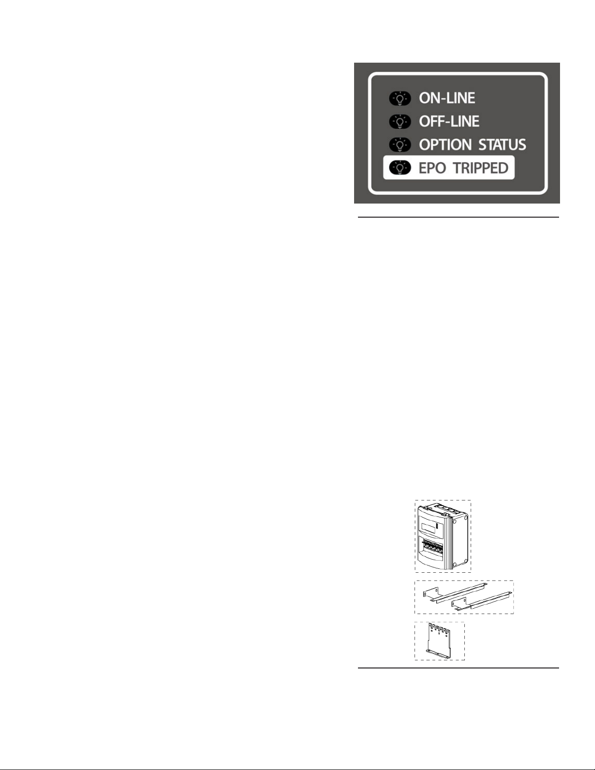
3.1 Package Contents . . . . . . . . . . . . . . . . . . . . . . . . . . . . . . . . . . . . . . . . . . . . . . . . . . . . . . . . . . . . . . . . . 6
4.0 Installation . . . . . . . . . . . . . . . . . . . . . . . . . . . . . . . . . . . . . . . . . . . . . . . . . . . . . . . . . . . . . . . . 6
4.1 Installation Kit Options . . . . . . . . . . . . . . . . . . . . . . . . . . . . . . . . . . . . . . . . . . . . . . . . . . . . . . . . . . . . . . 6
4.2 Installation Preparation. . . . . . . . . . . . . . . . . . . . . . . . . . . . . . . . . . . . . . . . . . . . . . . . . . . . . . . . . . . . . . 7
4.2.1 Elevated Operating Ambient . . . . . . . . . . . . . . . . . . . . . . . . . . . . . . . . . . . . . . . . . . . . . . . . . . . . . 7
4.2.2 Reduced Air Flow. . . . . . . . . . . . . . . . . . . . . . . . . . . . . . . . . . . . . . . . . . . . . . . . . . . . . . . . . . . . . . 7
4.2.3 Mechanical Loading. . . . . . . . . . . . . . . . . . . . . . . . . . . . . . . . . . . . . . . . . . . . . . . . . . . . . . . . . . . . 7
4.2.4 Circuit Overloading . . . . . . . . . . . . . . . . . . . . . . . . . . . . . . . . . . . . . . . . . . . . . . . . . . . . . . . . . . . . 7
4.2.5 Reliable Earthing . . . . . . . . . . . . . . . . . . . . . . . . . . . . . . . . . . . . . . . . . . . . . . . . . . . . . . . . . . . . . . 7
4.2.6 Disconnect Device . . . . . . . . . . . . . . . . . . . . . . . . . . . . . . . . . . . . . . . . . . . . . . . . . . . . . . . . . . . . . 7
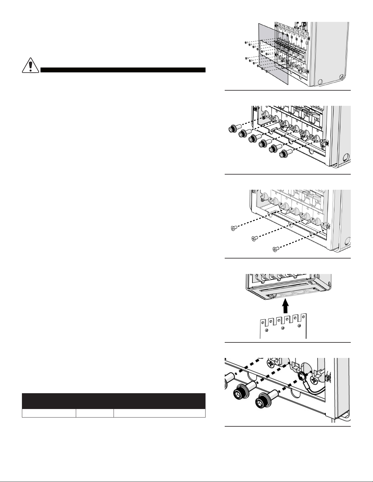
4.3 Battery Top Terminal Mount . . . . . . . . . . . . . . . . . . . . . . . . . . . . . . . . . . . . . . . . . . . . . . . . . . . . . . . . . . 8
4.3.1 Termination Bus Assembly. . . . . . . . . . . . . . . . . . . . . . . . . . . . . . . . . . . . . . . . . . . . . . . . . . . . . . . 8
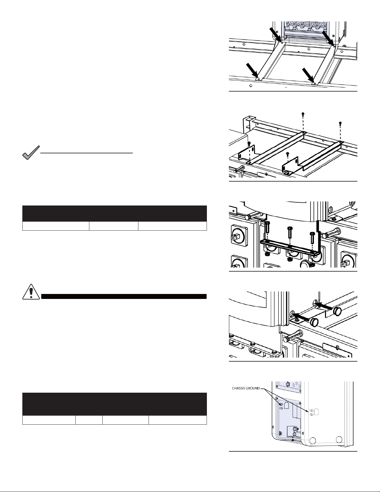
4.3.2 Battery Top Mounting Brackets . . . . . . . . . . . . . . . . . . . . . . . . . . . . . . . . . . . . . . . . . . . . . . . . . . . 9
4.4 Chassis Ground . . . . . . . . . . . . . . . . . . . . . . . . . . . . . . . . . . . . . . . . . . . . . . . . . . . . . . . . . . . . . . . . . . 10
4.5 Battery Positive Connection . . . . . . . . . . . . . . . . . . . . . . . . . . . . . . . . . . . . . . . . . . . . . . . . . . . . . . . . . 11
4.6 EPO Emergency Power O Switch Option. . . . . . . . . . . . . . . . . . . . . . . . . . . . . . . . . . . . . . . . . . . . . . 11
4.7 Alarm Contacts . . . . . . . . . . . . . . . . . . . . . . . . . . . . . . . . . . . . . . . . . . . . . . . . . . . . . . . . . . . . . . . . . . . 11
4.8 Auxiliary Power Port . . . . . . . . . . . . . . . . . . . . . . . . . . . . . . . . . . . . . . . . . . . . . . . . . . . . . . . . . . . . . . . 11
4.9 Electrical Test . . . . . . . . . . . . . . . . . . . . . . . . . . . . . . . . . . . . . . . . . . . . . . . . . . . . . . . . . . . . . . . . . . . . 11
4.10 Output Connections . . . . . . . . . . . . . . . . . . . . . . . . . . . . . . . . . . . . . . . . . . . . . . . . . . . . . . . . . . . . . . 12
4.11 Safety Covers . . . . . . . . . . . . . . . . . . . . . . . . . . . . . . . . . . . . . . . . . . . . . . . . . . . . . . . . . . . . . . . . . . . 13
4.12 Fuse Replacement . . . . . . . . . . . . . . . . . . . . . . . . . . . . . . . . . . . . . . . . . . . . . . . . . . . . . . . . . . . . . . . 13
5.0 Product Specications . . . . . . . . . . . . . . . . . . . . . . . . . . . . . . . . . . . . . . . . . . . . . . . . . . . .14
6.0 Models and Accessories . . . . . . . . . . . . . . . . . . . . . . . . . . . . . . . . . . . . . . . . . . . . . . . . . .15
Appendix A: Mechanical Drawings . . . . . . . . . . . . . . . . . . . . . . . . . . . . . . . . . . . . . 17
A.1 DCX Battery Disconnect Isometric View . . . . . . . . . . . . . . . . . . . . . . . . . . . . . . . . . . . . . . . . . . . . . . . 17
A.2 DCX Battery Disconnect Dimensions. . . . . . . . . . . . . . . . . . . . . . . . . . . . . . . . . . . . . . . . . . . . . . . . . . 18
A.3 DCX Chassis Ground Locations . . . . . . . . . . . . . . . . . . . . . . . . . . . . . . . . . . . . . . . . . . . . . . . . . . . . . 19

5C048-699-30 R03, Rev. B (01/2021)
1.01.0 Purpose and ApplicabilityPurpose and Applicability
This document covers the installation and operation of the DCX™Series top terminal battery disconnect system.
1.11.1 Product ModelProduct Model
This document applies to Alpha products in the following model congurations:
Table 1. DCX Model Congurations - Switch Only Versions (No Current Limiting)
DESCRIPTION PART NUMBER
400A DCX Battery Disconnect; -48VDC; w/shunt C016 -1001-10
600A DCX Battery Disconnect; -48VDC; w/shunt C016 -1003-10
800A DCX Battery Disconnect; -48VDC; w/shunt C016-1005-10
1000A DCX Battery Disconnect; -48VDC; w/shunt C016 -1007-10
1200A DCX Battery Disconnect; -48VDC; w/shunt C016 -1009 -10
Table 2. DCX Model Congurations - Magnetic Trip Versions
DESCRIPTION PART NUMBER
400A DCX Battery Disconnect; -48VDC; w/shunt C016 -198-10
600A DCX Battery Disconnect; -48VDC; w/shunt C016 -195-10
800A DCX Battery Disconnect; -48VDC; w/shunt C016-199-10
1000A DCX Battery Disconnect; -48VDC; w/shunt C016 -196 -10
1200A DCX Battery Disconnect; -48VDC; w/shunt C016-207-10
For a list of mounting kit and accessory part numbers, refer to Section 6 on Page 17.
2.02.0 Theory of OperationTheory of Operation
The DCX disconnect product family includes multiple amperage ratings and installation mounting schemes to provide a
DC or Battery source disconnect device for use in Telecom +24 or -48VDC systems as well as solar-alternate energy
or other DC applications. The primary application for the DCX system is to provide over-current protection for battery
sourced equipment and wiring. The secondary function is to provide a service disconnect in order to maintain batteries or
to shut down the battery source connection in an emergency.
2.12.1 Circuit Breaker Trip RatingsCircuit Breaker Trip Ratings
The DCX product family includes circuit breaker trip ratings of 400, 600, 800, 1000, and 1200A. The electrical
conguration allows for both positive and negative connected systems as factory congured options. The DCX system
includes a circuit breaker or switch, an internal input and output copper bus structure, a steel inner housing, a circuit
board, and a ame retardant plastic outer housing.
2.22.2 Mounting CongurationsMounting Congurations
Several dierent mounting bracket option kits provide battery top terminal mounting congurations for numerous battery
manufacturer's cell congurations.
This manual suits for next models
10
Table of contents
Other Alpha Industrial Equipment manuals