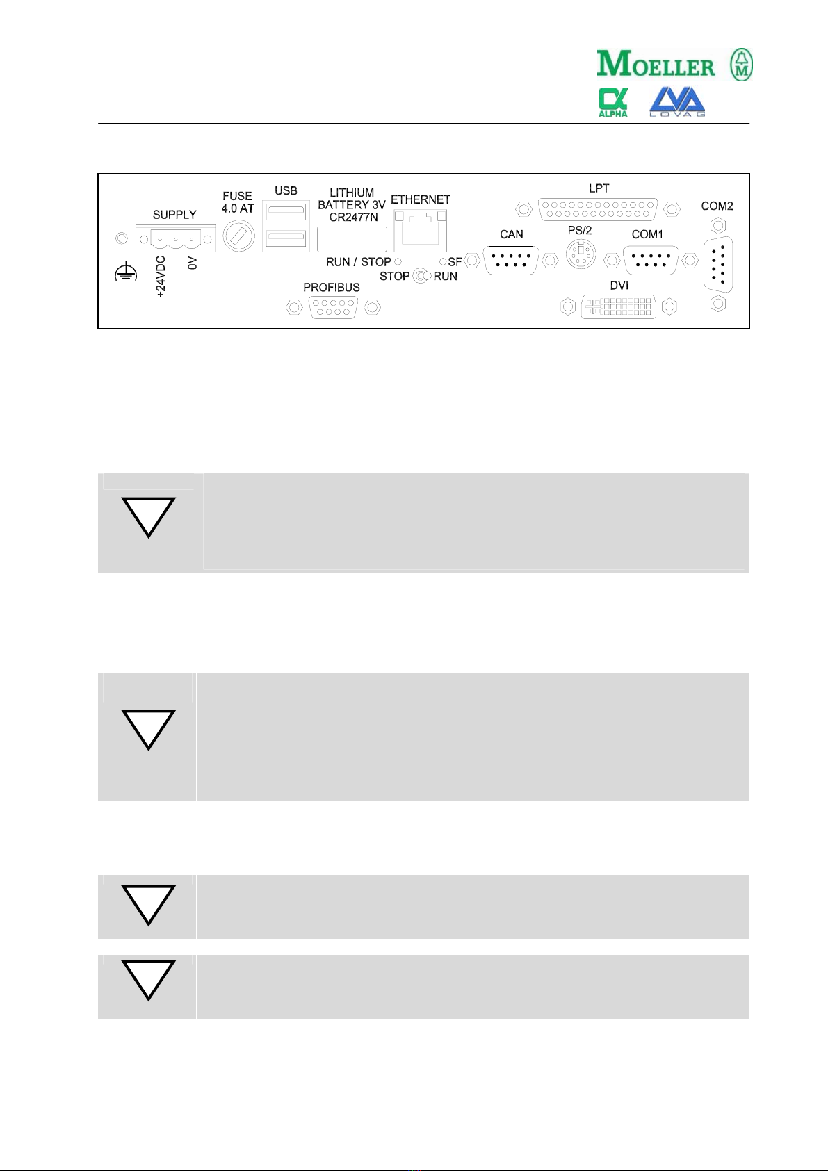
Alpha Moeller XVC-601-GTR Series User manual

06/04 AWA2720-2144
1/4
Montageanweisung
Installation Instructions
XVC-601-GTR-...
XVC-601-GTI-...
XCC-601-DVI-...
AWB2720-1522D
AWB2720-1522GB
Lieferumfang – Packing list
Gerät XVC-601-GTx, Konterrahmen, Dichtung, Gerät XCC-601-DVI, SV-Stecker
4 Befestigungsmuttern, SV-Stecker Device XCC-601-DVI, Power-Supply connector
Device XVC-601-GTx, fixing frame, seal,
4 securing nuts, Power-Supply connector
Frontplatten-Ausschnitt / Abmessungen - Front cutout / dimensions
Ausschnitt – cutout
[mm]
Abmessungen
– dimensions
[mm]
A B BxHxT / WxHxD
XVC-601-GTx-10 329 +0/-1 238 +0/-1 345 x 260 x 109
XVC-601-GTx-12 344 +0/-1 262 +0/-1 361 x 279 x 109
XVC-601-GTx-15 410 +0/-1 315 +0/-1 427 x 332 x 109
XCC-601-DVI - - 284 x 170 x 77
Manual
Das Gerät ist für den industriellen
Einsatz geeignet (ÆEN 61000-6-
2/3)
The device is suitable for use in
industrial environment (ÆEN
61000-6-2/3)
A
B
B
XCC
-
601
-
...
XVC
-
601
-
...

06/04 AWA2720-2144
2/4
Montageanweisung
Installation Instructions
Montage – Mounting
1. Das XVC-601 von vorne in den Ausschnitt der Fronttafel schieben.
Push the XVC-601 from the front into the cutout of the front panel.
2. Die Frontdichtung muss zwischen Frontplatte und Fronttafel flach und rundum gleichmässig
aufliegen.
The front seal must be level and evenly positioned between the front plate and the front panel.
3. das Gerät im Ausschnitt zentrieren.
Centering the device in the cutout
4. Das Gerät mit dem mitgelieferten Befestigungsrahmen von der Rückseite her gleichmässig mit
den 4 Sicherungsmuttern festschrauben (maximal bis der Frontrahmen umlaufend an der
Fronttafel anliegt).
Secure the device from the rear with the supplied fixing frame. For this use the 4 securing nuts
which should be tightened evenly from the rear until the front frame is flush with the front panel all
round.
Die Geräte der Reihe XCC-601 werden alle in einem Schaltschrank eingebaut. Die Befestigung erfolgt
durch 4 Schrauben an den Befestigungswinkeln im Schaltschrank. Der Einbau sollte senkrecht mit den
Stecker nach unter erfolgen, um eine Luftkonvektion zu ermöglichen.
All XCC-601 series devices are mounted in a control panel. They are fastened with 4 screws at the
strapping in a control panel. The device should be mounted vertically with connectors on the lower side to
allow air convection.
Zur Vermeidung einer Überhitzung des Gerätes während dem Betrieb ist
folgendes zu beachten:
- Allfällige Kühlschlitze müssen frei sein, um die Systemkühlung zu gewährleisten
- Vermeiden Sie die direkte Sonneneinstrahlung auf die Front (XVC-devices)
- Der Neigungswinkel zum senkrechten Einbau darf max. ± 35° betragen
The following must be ensured in order to prevent the device from overheating
during operation:
- The cooling slots must always be free in order to ensure the proper cooling of
the system.
- Avoid the exposure of the flat screen to direct sunlight.
- The mounting angle must not exceed ± 35° from the vertical, if these conditions
cannot be met, the mounting of an external fan is recommended.
Achten Sie auf einwandfreien Sitz der Dichtung an der Fronttafel. Bei Geräten mit
Runddichtung müssen die beiden Enden der Dichtung an der Geräteunterseite
bündig montiert werden.
Vermeiden Sie Drehmomente grösser 0.5 Nm, das Gerät könnte sonst beschädigt
werden.
Die Fronttafel darf eine maximale Dicke von 5mm nicht überschreiten.
Ensure that the seal is fitted correctly on the front panel. For devices with a round
seal the two ends must be at the lower side of the device and should fit together
without a gap.
Avoid tightening torques of greater than 0.5 Nm as this could otherwise damage
the device.
The thickness of the front panel must not exceed 5 mm.

06/04 AWA2720-2144
3/4
Montageanweisung
Installation Instructions
Anschlüsse – Connections
24VDC Stromversorgung – 24VDC Power supply
Das XVC/XCC-601 ist ein Gerät der Schutzklasse 3. Die Systemversorgung hat mit
Sicherheitskleinspannung SELV 24VDC (safety extra-low voltage) zu erfolgen. Die Versorgung ist NICHT
galvanisch getrennt.
The XVC/XCC-601 device belongs to protection class 3. The system power supply must be provided with
a 24VDC SELV voltage. The power supply is NOT isolated.
Es darf nur die spezifizierte Sicherung eingesetzt werden.
Eine zu gross dimensionierte Sicherung kann die Zerstörung des Geräts oder der
externen Komponenten zur Folge haben!
Only the specified fuse must be used.
An over-dimensioned fuse can result in the destruction of the device or of the
external components!
Batterie - Battery
Das Gerät beinhaltet eine 3V Lithium Batterie.
The device contains a 3V Lithium battery.
Achtung! / Caution!
Es besteht Explosionsgefahr, wenn die Batterie durch einen falschen Typ ersetzt
wird! Die Batterie darf nur durch instruiertes Service-Personal ersetzt werden.
Gebrauchte Batterien müssen fachgerecht entsorgt werden.
Risk of explosion if battery is replaced by an incorrect type. Replacement of
battery must be done by instructed service personal only.
Used batteries should be disposed via specialized dealers.
Schnittstellen – Interfaces
An nachfolgende Schnittstellen angeschlossene Kabelleitungen sind von
niederspannungsführenden Leitungen getrennt zu verlegen.
Cables connected to the following interfaces must be laid separately from the
low-voltage cables.
Für einen störungsfreien Betrieb müssen zwingend abgeschirmte Kabel
verwendet werden.
To ensure disturbance-free operation, it is strongly recommended to use cables
with shield.

06/04 AWA2720-2144
Moeller GmbH, Industrieautomation, D-53105 Änderungen 06/04 AWA2720-2144 4/4
© 2004 by Moeller GmbH vorbehalten
Montageanweisung
Installation Instructions
COM1/COM2-Schnittstelle - COM1/COM2-Interface
Diese Schnittstelle ist nicht galvanisch getrennt. Der GND-Anschluss liegt direkt auf dem
Gehäusepotential.
This interface is not isolated. The GND connection is implemented directly on the housing potential.
Ethernet-Schnittstelle – Ethernet interface
Der Ethernet-Anschluss ist PC-kompatibel (RJ45 10/100MBit). Die Verbindung zu einem HUB erfolgt über
ein 1:1 Cat 5 Kabel mit RJ45 Anschlüssen. Für eine direkt Verbindung zu einem anderen Gerät wird ein
ausgekreuztes Kabel benötigt (crosslink cable).
The Ethernet-Interface is PC-compatible (RJ45 10/100MBit). For the connection to a HUB a standard
Ethernet cable (1:1) is required. For a direct connection to another device a crosslink cable is required.
DVI-Schnittstelle - DVI-Interface (XCC-601-DVI...)
Die DVI-Schnittstelle entspricht dem Single Link DVI-D Standard und dient zum Anschluss eines DVI-
Panels.
The DVI-Interface is compatible to the DVI-D Standard and is used to connect a DVI-Panel.
LPT-Schnittstelle - LPT-Interface
Die LPT-Schnittstelle ist PC-kompatibel (Centronix) und dient zum Anschluss eines Druckers mit einem
Standard Druckerkabel. Die LPT Schnittstelle ist nicht galvanisch getrennt.
The LPT Interface is PC-compatible (Centronix) and is used to connect a printer via a standard printer
cable. The LPT-interface is not isolated.
PS/2-Schnittstelle - PS/2-Interface
Der Tastatur-Anschluss ist PC-kompatibel (PS/2) und dient zum Anschluss einer Standard PC-Tastatur.
Die PS/2 Schnittstelle ist nur für Test und Servicezwecke vorgesehen.
The keyboard terminal is PC-compatible (PS2) and is used to connect a standard PC keyboard. The PS/2
interface is only provided for testing and service tasks.
USB-Schnittstelle - USB-Interface
Die USB Schnittstelle wird derzeit nicht unterstützt.
The USB Interfaces is not supported at the moment.
CAN Signal
1 -
2 CAN LOW
3 CAN GND
4 -
5 -
6 CAN GND
7 CAN HIGH
Sub-D 9 Pol 8 -
male 9 -
Profibus Signal
1 -
2 -
3 RXD/TXD+
4 -
5 GND
6 +5V
7 -
Sub-D 9pol 8 RXD/TXD-
female 9 -
COM1 Signal
1 DCD-
2 RXD
3 TXD
4 DTR-
5 GND
6 DSR-
7 RTS-
Sub-D 9pol 8 CTS-
male 9 RI-
COM2 (XCC-601) Signal
1 -
2 RXD
3 TXD
4
12VDC
5 GND
6 -
7 -
Sub-D 9pol 8 -
male 9
12VDC
5
94
83
72
61
5
94
83
72
61
5
94
83
72
61
1
6
2
7
3
8
4
9
5
This manual suits for next models
2