Alpha ARS-SM01 User manual


1
INTRODUCTION
The ARS-SM01 sensor kit is used to detect whether there are obstacles behind the vehicle to visually and audibly assist the driver when the
vehicle is moving backwards. This product is extremely useful when the vehicle is reversed into a parallel, perpendicular, or an angled parking
space.
PACKAGE CONTENTS
The following items are included in the package:
Master & Slave Sensors Buzzer
BGC Button
NOTE: If any of the items, mentioned above, are not included in the packaging or are damaged in any way, contact your reseller immediately.

2
PRECAUTIONS
The ARS-SM01 is a product that assists drivers in normal parking conditions. The responsibility to control the vehicle and avoid collisions still
belongs to the driver.
INSTALLATION PRECAUTIONS
cMake sure that the surface of the inner bumper is as clean and smooth as possible before installing the sensors onto it. Any dents or
scratches could degrade the performance of the radar.
dThe proper installation order is, install the cables first, then connect them to the power/ground connections, then connect the sensors to the
cables, and then attach the sensors to the bumper.
eMake sure that the surface of the outer bumper, especially in front of the radar sensors, is as clean as possible. Dirt, clay, snow, stickers, or
any other item in front of the sensors could interfere with its normal operation.
fIf the bumper was damaged due to an impact, the position, stability, and angle of the sensors must be checked for any visible offset from its
original installation. A recalibration might be required.
gIf the bumper was repainted, a recalibration must be performed. Minor performance changes like the maximum achievable detection distance
might occur.
APPLICATION PRECAUTIONS
cNormal operation of the sensors will be interfered with or obstructed when the vehicle is being towed another vehicle.
dAbnormal operation might occur when the reversing speed limit of 15 km/h is exceeded.
eThe position of the sensors, the properties of the bumper, and the surroundings like different types of ground surfaces might promote
abnormal operation of the sensors.
x If the vehicle transports a heavy load or passes over a ditch cover or a large reflection, false alarms might occurs at a larger distance
from the vehicle.
x Low obstacles might not be detected if the sensors were installed too high or tilted upwards too much.
INSTALLATION
The ARS-SM01 can be installed onto the inside of the rear bumper of most vehicles. To start the installation, unbox the ARS-SM01 and
remove the rear bumper from the vehicle.
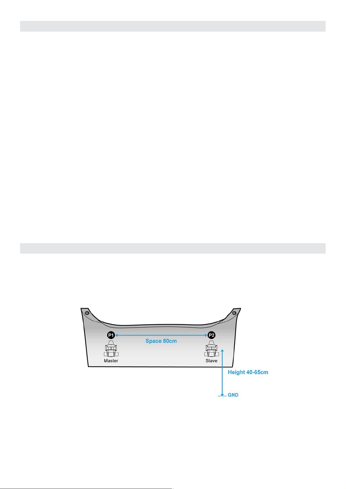
Install the Master sensor onto the inside left corner of the rear
bumper.
Install the Slave sensor onto the inside right corner of the rear
bumper.
The distance between the two sensors must be 80 cm. The height of the sensors must be between 40 cm and 65 cm from the ground.

3
The flat side of the sensors must point to the back of the of the vehicle with the
curved side to the front. The cables must point up.
The sensors must be installed at a 90-degree angle, perpendicular to the ground.
The installation angle (±θ) depends on the height of the bumper from the ground.
Installation Height (±10 cm) Installation Angle (θ)
40 cm 0° to 5°
45 cm -5° to 5°
50 cm -5° to 0°
55 cm -5° to 0°
60 cm -10°
65 cm -10°
If the inside of the bumper is uneven, the gap between the sensor and the
uneven bumper should not be more than 1 mm.
The sensors will receive power from the reverse light of the vehicle. Connect the power (12V) and ground cables to the power (12V) and
ground cables of the reverse light.
When installation is complete, the bumper can be re-installed onto the vehicle. No electronic/electric products or equipment that contain metal
should be between the sensors and the area of detection.
INITIALIZATION
To initialize the ARS-SM01, after the installation, clear the area behind the vehicle (1 meter) of any obstructions and press the BGC toggle
switch. BGC stands for Background Check. The initialization process is as follows:
x With the vehicle turned on, power the reverse lights by shifting the gear stick/selector (manual/automatic) into the reverse position.
x Toggle the BGC switch to the on (I) position.
x Wait until the buzzer makes a sound for longer than 1 second.
x Toggle the BGC switch to the off (O) position.
x Wait until the buzzer sound stops (about 3 seconds).
After the buzzer sound stopped, the initialization process is complete and the ARS-SM01 is ready for use.
Cable
Side View
+θ
-
θ
0 ~ 1 mm

4
DETECTION AREA
The ARS-SM01 can detect obstacles in the area behind the vehicle (maximum distance 5m). The buzzer will sound when an object is detected
within the detection area and increase the sound intensity as the object gets closer to the vehicle. The sensor detection area is illustrated in the
figure below:
TECHNICAL SPECIFICATIONS
Power Supply 9V to 18V Power Consumption Less than 0.9 Watt (average)
Dimensions (L x W x H) 45 mm x 39 mm x 34.8 mm Weight 18 gram
Operating Temperature -40°C to 85°C Storage Temperature N/A
Operating Humidity 10% to 90% (Non-condensing) Storage Humidity 0% to 95% (Non-condensing)
Frequency Range 77 GHz to 81 GHz Signal Range 20 cm to 500 cm
FOV (Horizontal) 130° FOV (Vertical) 50° (10° default tilt upwards)
Cable Length (Master-Slave) M-197 cm / S-147 cm Cable Length (Slave-Buzzer) 150 cm
Cable Length (Slave-BCR) 120 cm
5 m

5
Warning Statement
FCC 15b devices (15.105)
This equipment has been tested and found to comply with the limits for a Class B digital device, pursuant to part 15 of the FCC rules. These
limits are designed to provide reasonable protection against harmful interference in a residential installation. This equipment generates, uses
and can radiate radio frequency energy and, if not installed and used in accordance with the instructions, may cause harmful interference to
radio communications. However, there is no guarantee that interference will not occur in a particular installation.
If this equipment does cause harmful interference to radio or television reception, which can be determined by turning the equipment off and on,
the user is encouraged to try to correct the interference by one or more of the following measures:
Reorient or relocate the receiving antenna.‐
Increase the separation between the equipment and receiver.‐
Connect the equipment into an outlet on a circuit different from that to which the receiver is connected.‐
Consult the dealer‐or an experienced radio/TV technician for help.
FCC Part 15.21 information for user
You are cautioned that changes or modifications not expressly approved by the party responsible for compliance could void your authority to
operate the equipment.
FCC Part 15.19
This device complies with Part 15 of the FCC Rules. Operation is subject to the following two conditions: (1) this device may not cause harmful
interference and (2) this device must accept any interference received, including interference that may cause undesired operation
Table of contents
Popular Radar manuals by other brands

Endress+Hauser
Endress+Hauser Micropilot FMR62B PROFINET with Ethernet-APL technical information

Telephonics
Telephonics RDR-1600 installation manual

JRC
JRC RADAR 1500 MKII instruction manual

Magnetrol
Magnetrol pulsar RX5 Installation and operating manual

Furuno
Furuno FRS1000 Quick operating guide

Carmanah
Carmanah G Series Cabinet Door Replacement Guide

Endress+Hauser
Endress+Hauser Micropilot FMR66B PROFINET with Ethernet-APL technical information

DITEC
DITEC AXP2 installation manual

RHYTHM
RHYTHM HAWKEYE FREEWAYS Maintenance Guide

Blickfeld
Blickfeld Qb2 Quick start manual

Blackbe;rry
Blackbe;rry RADAR-L installation guide

IDS GeoRadar
IDS GeoRadar STREAM DP user manual