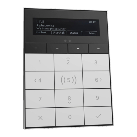
alphatronics AlphaVision ML User manual

Alphatronics b.v. –Watergoorweg 71 –3861 MA Nijkerk –Tel: +31 33 2459944 –Fax: +31 33 2453149
www.alphatronics.eu
Service Manual
for the installer

Installer manual AlphaVision ML Rev. 3.60 01-01-2015 2
CONTENTS
INTRODUCTION ....................................................................................................................................... 7
Purpose of this manual..................................................................................................................... 7
ALPHAVISION ML SPECIFICATIONS.......................................................................................................... 7
GENERAL GUIDELINES ........................................................................................................................... 12
GUIDELINES GRADE 2 ............................................................................................................................ 13
INSTALLATION........................................................................................................................................ 14
Installing the AlphaVision ML control panel................................................................................... 14
Applying power to the AlphaVision ML .......................................................................................... 14
Connections on the AlphaVision ML main board ........................................................................... 16
Explanation about jumpers, LED’s and fuses on the AlphaVision ML ............................................ 17
Connecting the AlphaVision ML to a LAN connection.................................................................... 18
Connecting the AlphaVision ML to a analog (PSTN) telephone line............................................... 18
Connecting hard-wired inputs to the AlphaVision ML control panel ............................................. 18
Inputs with EOL............................................................................................................................... 19
Connecting outputs on the AlphaVision ML ................................................................................... 19
Relay outputs.................................................................................................................................. 19
Open Collector outputs .................................................................................................................. 19
LS output......................................................................................................................................... 20
Vocal support for users................................................................................................................... 20
Keypads for the AlphaVision ML..................................................................................................... 21
Connecting LCD keypads to the AlphaVision ML............................................................................ 21
Connecting LED keypads to the AlphaVision ML ............................................................................ 22
Connecting an external Proximity Reader to the AlphaVision ML ................................................. 23
Address settings for the Proximity Reader..................................................................................... 23
Visualizing address settings of the proximity reader...................................................................... 23
Changing address settings of the proximity reader........................................................................ 24
OC output on the proximity reader ................................................................................................ 24
Connecting a AlphaVision Input + 8OC module.............................................................................. 24
Connecting an AlphaVision I/O module including a power supply ................................................ 25
Wireless expansion module (wireless detectors and keyfobs) ...................................................... 27
PSTN expansion .............................................................................................................................. 28
GSM/GPRS expansion..................................................................................................................... 28
Replacing an AlphaVision NG for a AlphaVision ML ....................................................................... 29
POWER CONSUMPTION AND BATTERY CALCULATIONS ....................................................................... 30
Power consumption........................................................................................................................ 30
Example calculation for minimal battery capacity ......................................................................... 31
Maximum distance between an expansion module and its power supply.................................... 32
Battery test and mains failure ........................................................................................................ 34
Telephone line test ......................................................................................................................... 34
STARTING UP THE ALPHAVISION ML..................................................................................................... 34
Programming the AlphaVision ML with a computer ...................................................................... 34
OPERATING THE ALPHAVISION ML........................................................................................................ 35
Incorrect or incomplete code (V2.00 and above)........................................................................... 36
Entry/Exit mode (V2.00 and above) ............................................................................................... 36
Description of the LED’s on the keypad.......................................................................................... 37
LCD/Proximity keypad .................................................................................................................... 38
Enrolling Proximity tags in the LCD/Prox keypad ........................................................................... 38

Installer manual AlphaVision ML Rev. 3.60 01-01-2015 3
Arming- and disarming with a proximity tag on a LCD/Proximity keypad ..................................... 38
LED keypad...................................................................................................................................... 38
Proximity Reader ............................................................................................................................ 38
Arming- and disarming via the external Proximity Reader............................................................. 39
Access control via the external Proximity Reader .......................................................................... 39
Acoustic signals of the AlphaVision ML .......................................................................................... 39
PROGRAMMING .................................................................................................................................... 40
USER MENU ........................................................................................................................................... 41
Date and Time................................................................................................................................. 42
Time switch (V3.20 and above) ...................................................................................................... 43
Users ............................................................................................................................................... 43
Guard code ..................................................................................................................................... 45
Days of the week ............................................................................................................................ 45
Sections........................................................................................................................................... 45
User name....................................................................................................................................... 45
Duress code .................................................................................................................................... 45
Telephone number ......................................................................................................................... 46
Speech and sound........................................................................................................................... 46
Open zones ..................................................................................................................................... 47
Maintenance................................................................................................................................... 47
Walktest zones................................................................................................................................ 47
View open zones............................................................................................................................. 48
Test LED & LCD................................................................................................................................ 48
IP connection .................................................................................................................................. 48
Installer access................................................................................................................................ 48
Send testreport............................................................................................................................... 48
Access via APP (V2.00 and above) .................................................................................................. 48
APP key ........................................................................................................................................... 48
Bypassing ........................................................................................................................................ 49
Information present........................................................................................................................ 49
INSTALLER MENU .................................................................................................................................. 50
INPUTS MENU........................................................................................................................................ 51
Zone type ........................................................................................................................................ 53
Zone options ................................................................................................................................... 55
Doorbell option............................................................................................................................... 55
Bypass ............................................................................................................................................. 56
Zone sections .................................................................................................................................. 56
Inactivity ......................................................................................................................................... 56
Zone characteristics........................................................................................................................ 56
ENROLL MENU....................................................................................................................................... 56
Enroll wireless zones....................................................................................................................... 57
Enroll wirelesss keyfobs.................................................................................................................. 58
Erase wireless Keyfobs.................................................................................................................... 58
Keyfob name................................................................................................................................... 58
Wireless options ............................................................................................................................. 59
OUTPUT MENU...................................................................................................................................... 60
LS output......................................................................................................................................... 61
Entry/Exit buzzer............................................................................................................................. 62
Trouble buzzer ................................................................................................................................ 62

Installer manual AlphaVision ML Rev. 3.60 01-01-2015 4
Alarm relay output 1 and 2............................................................................................................. 62
Open collector output 3 and 4........................................................................................................ 63
Outputs 5-8 (V3.00 and above) ...................................................................................................... 63
KNX outputs (V3.50 and above)...................................................................................................... 63
Activate trigger output via a PIN-code, keyfob or (mobile) phone ............................................... 64
Quick arming................................................................................................................................... 68
Bypass ............................................................................................................................................. 68
Auto-reset (1-3 times) .................................................................................................................... 68
Panic alarm ..................................................................................................................................... 68
Duress code .................................................................................................................................... 68
Partial arming.................................................................................................................................. 68
Complete arming ............................................................................................................................ 69
Aux button ...................................................................................................................................... 69
Backlight and section LED screensaver option ............................................................................... 69
Arming- and disarming in historical log.......................................................................................... 69
Configuration .................................................................................................................................. 69
Jamming detection ......................................................................................................................... 70
House Identity................................................................................................................................. 70
Usercodes (V2.00 and higher) ........................................................................................................ 70
EN50131 mode (V2.00 and higher) ................................................................................................ 70
LS on walktest (V2.00 and higher) .................................................................................................. 71
Supervision Loud Alarm (V2.00 and higher) ................................................................................... 71
Doorbell via LS (V3.00 and higher) ................................................................................................. 71
EOL Resistor (V3.20 and higher) ..................................................................................................... 71
Total/Partial arming (V3.50 and higher)......................................................................................... 72
Keyswitch option (V3.60 and higher) ............................................................................................. 72
Battery monitoring (V3.60 and higher) .......................................................................................... 72
TIMERS MENU ....................................................................................................................................... 73
Alarm cancel ................................................................................................................................... 73
Inactivity ......................................................................................................................................... 73
Supervision alarm ........................................................................................................................... 74
Entry- and Exit delay times ............................................................................................................. 74
Siren (LS) time................................................................................................................................. 74
LS/AL1 delay.................................................................................................................................... 74
Outputs 1 to 8 activation time........................................................................................................ 74
230V power failure reporting delay (V3.50 and higher)................................................................ 76
DIALER ................................................................................................................................................... 76
PSTN/GSM REPORTING ......................................................................................................................... 78
Central station reporting 1 / 2 ........................................................................................................ 79
Central station telephone number ................................................................................................. 79
Account number ............................................................................................................................. 79
Protocol........................................................................................................................................... 79
Dial attempts .................................................................................................................................. 79
Private telephone settings.............................................................................................................. 80
Private telephone reporting ........................................................................................................... 80
Private telephone number.............................................................................................................. 80
Protocol........................................................................................................................................... 81
Dial attempts .................................................................................................................................. 81
Stop dial sequence for private reporting (v2.00 and higher) ......................................................... 81
Alarm messages .............................................................................................................................. 81
Central station messages................................................................................................................ 81

Installer manual AlphaVision ML Rev. 3.60 01-01-2015 5
Private telephone messages........................................................................................................... 82
Test report ...................................................................................................................................... 82
Time test report.............................................................................................................................. 82
Diverse options ............................................................................................................................... 82
Telephone line monitoring ............................................................................................................. 82
GSM active...................................................................................................................................... 82
Pincode Simcard ............................................................................................................................. 82
SMS-Servicenumber ....................................................................................................................... 82
Roaming allowed ............................................................................................................................ 83
Acceptance mode ........................................................................................................................... 83
GSM/GPRS Fault codes (V2.00 and higher) .................................................................................... 83
IP/GPRS REPORTING.............................................................................................................................. 83
General LAN settings ...................................................................................................................... 87
Own IP-address............................................................................................................................... 87
MAC-address................................................................................................................................... 87
Subnetmask .................................................................................................................................... 87
Gateway IP-address ........................................................................................................................ 87
Local port number .......................................................................................................................... 87
Messages ........................................................................................................................................ 87
IP Configuration .............................................................................................................................. 88
DNS settings.................................................................................................................................... 88
General GPRS settings .................................................................................................................... 88
GPRS settings .................................................................................................................................. 88
Roaming allowed ............................................................................................................................ 88
SIM Card PIN code .......................................................................................................................... 88
GPRS always active ......................................................................................................................... 89
Standard Dialer D1 settings ............................................................................................................ 89
Standard D1 active.......................................................................................................................... 89
Monitoring station IP address ........................................................................................................ 89
Monitoring station port number .................................................................................................... 89
Monitoring station account number .............................................................................................. 89
Polling interval ................................................................................................................................ 89
Test report interval......................................................................................................................... 89
Communication method................................................................................................................. 89
Backup Dialer D2 settings ............................................................................................................... 90
The programming options for Backup D2 are equal to the options used for Standard D1............ 90
Diverse LAN/GPRS settings ............................................................................................................. 90
Connecting to the APP (V3.00 and higher) ..................................................................................... 91
GPRS backup transmission.............................................................................................................. 92
REMOTE SERVICE................................................................................................................................... 92
Remote service through the GSM plug-on board........................................................................... 92
Remote service PSTN/GSM............................................................................................................. 93
Remote connection via IP(LAN) ...................................................................................................... 93
Download code............................................................................................................................... 94
SPEECH RECORDING .............................................................................................................................. 94
REPORTING TO PRIVATE (MOBILE) TELEPHONE............................................................................. 94
MAINTENANCE ...................................................................................................................................... 95
View open zones............................................................................................................................. 96
Zone walktest.................................................................................................................................. 96
View zones ...................................................................................................................................... 97
Field strength explanation.............................................................................................................. 97

Installer manual AlphaVision ML Rev. 3.60 01-01-2015 6
Walktest zone ................................................................................................................................. 97
Test LED & LCD................................................................................................................................ 97
Test outputs.................................................................................................................................... 97
Reset user code............................................................................................................................... 98
Default factory settings .................................................................................................................. 98
IP connection .................................................................................................................................. 98
CONNECTING A COMPUTER ........................................................................................................... 98
Transmit testmessage (V2.00 and higher)...................................................................................... 98
Test Mode (V3.20 and higher) ........................................................................................................ 98
INSTALLATION CODE....................................................................................................................... 98
RESET INSTALLER AND SUPERVISOR CODE..................................................................................... 99
DIAGNOSE TOOL ............................................................................................................................. 99
EVENT LOG...................................................................................................................................... 99
Firmware upgrade (bios flash) of the AlphaVision ML ................................................................. 100
DEFAULT PROGRAMMING ALPHAVISION ML...................................................................................... 105
Codes ............................................................................................................................................ 105
Installation menu.......................................................................................................................... 105
APPENDIX A: DETECTOR DEPLOYMENT........................................................................................ 107
APPENDIX B: KEYFOB TRANSMITTER ASSIGNMENT ..................................................................... 108
APPENDIX C: SOCIAL ALARM TRANSMITTER ................................................................................ 108
APPENDIX D: EVENT CODES ......................................................................................................... 109
APPENDIX E: KEYPAD ADDRESSING .............................................................................................. 114
APPENDIX F: EXPANSION MODULE ADDRESSING ........................................................................ 114
APPENDIX G Declaration of conformity Telit GSM/GPRS module................................................ 115
APPENDIX H Installing the FLASH program................................................................................... 116

Installer manual AlphaVision ML Rev. 3.60 01-01-2015 7
INTRODUCTION
Purpose of this manual
The purpose of this manual is to provide the installer step by step instructions for installing and
programming the Alpha Vision ML security system. The manual is intended to make installers familiar with
the operation and construction of the AlphaVision ML and its components.
The AlphaVision ML was designed and tested in accordance with the applicable standards on stability,
reliability and immunity to electrical interferences from the environment.
General guidelines
Frequently check the Alphatronics website for the latest tips and instructions, www.alphatronics.nl /
security installers and click on the button "Service & Support. Contact the sales department to receive a
username and password.
When the ML Alpha Vision is part of security installation for which a certificate should be issued, follow the
instructions carefully in this guide regarding comments "for a grade 2 installation it .... ' (see also the Grade
2 installation instructions).
ALPHAVISION ML SPECIFICATIONS
Versions: The AlphaVision ML is available in a synthetic casing and a metal casing, both with the same
power and battery pack (2700mAh) for use up to grade 2 installations.
Identification: On the inside of each enclosure a label is applied, enabling the device to be identified. On
each label the name of the manufacturer, type, batch number (starting with a capital B, B014 for example,
batch number 014), the security grade and the environmental class is mentioned.
For the synthetic casing of the AlphaVision ML the label is placed on the inside of the lid. For the keypad the
label is placed on the inside of the rear shell. For the metal casing of the AlphaVision ML and the I/O module
the label is placed on the rear inside of the cabinet.
Labels must not be removed!
If the installation does not meet to grade 1 or grade 2 the labels MUST be removed!
The individual label with serial number must never be removed.
For the PSTN and GSM plug-on dialers loose identification labels are provide with each plug-on dialer.
These labels should be placed in the cabinet of the control panel if the installation complies with grade 1 or
grade 2.
Applications: Residential, retail and light commercial applications.
Partitions: 8 separate partitions possible.
Zones: Standard 12 hard-wired zones and expandable up to 100 hard-wired zones using Input or I/O
modules. A maximum of 32 wireless zones using a wireless expansion module can be connected.
Expansion modules (a maximum of 4 modules can be connected):
Input + 8 o.c. module for 8 hard-wired zones and 4 open collector outputs.
I/O module including 3A power supply for 8 hard-wired zones, 2 potential free relay outputs, 2 open
collector outputs and a speaker (LS) output.
Wireless expansion module for incorporating wireless detectors and keyfob transmitters.

Installer manual AlphaVision ML Rev. 3.60 01-01-2015 8
Zone names: Standard Library with a choice of 28 standard zone names or freely programmable per zone.
Speech reporting: If the control panel is equipped with a speech plug-on board alarm and status
information can be transmitted as speech messages to fixed or mobile telephone numbers.
2-way voice capability: If the control panel is equipped with a speech plug-on board which is connected to a
keypad (max. 1 piece) containing an integrated microphone and speakers (art.nr. 004121) or an external
speakerphone, a remote 2-way voice connection can be established.
Zone types: Direct, Delayed 1-5, 24-hour quiet, 24-hour loud, Fire, Social alarm, Hold up, Sabotage,
Follower, Follower Delayed, Emergency door, Technical alarm, Gas, Water, Temperature, Direct dialer input
and Key switch.
Zone characteristics: N.C.(normally closed), N.O. (normally open), End of Line (N.O.), End of Line (N.C.),
Wireless and Not active. For specifications about End of Line resistors see chapter “Inputs with EOL
resistors”.
Outputs:
Loudspeaker (LS) output 8 ohm 15W
2 potential free relay outputs (max. current through the contact is 300mA @ 12VDC)
2 open collector (O.C.) outputs 200mA. The maximum cable length on this output may not exceed
3m.
4 terminals for (outgoing) +12V power supply, divided in a 3-pole terminal connector (secured by a
500mA polyfuse) and an extra +12V terminal connector next to the outputs (also secured by a
500mA polyfuse).
RS-485 bus (including a +12V terminal, secured bu a 500mA polyfuse)
The +12V connectors provide a continuous supply between 9.0 and 15.5 VDC and each can deliver a total
current consumption of 500mA. The total (of all +12V connections) power consumption for a grade 2 system
may not exceed 500mA. If a higher power consumption is necessary, it must be solved by means of an
additional power supply, for example with the aid of an I/O module. The maximum ripple on the output
voltage is 250mV.
User codes: Max. 90 user codes (more than one user code can be programmed as a supervisor code), duress
code option, 1x installer code. Users have the choice of using a PIN-code or Proximity tag (optional). The
total of both PIN-codes and proximity tag’s is 90. PIN-code 000000 is an invalid code. Based on 6-digit PIN-
codes there are 999,999 valid codes possible. If the duress code option is used, there are 499,999 valid
codes. The code of a proximity pass is automatically translated into a 6-digit PIN code
Keypads: Minimum 1 piece and maximum 8 pieces LCD or LCD/PROXIMITY keypads can be connected. One
keypad can be equipped with a speaker and microphone (art.nr. 004128).
Proximity Reader: Maximum 1 external proximity reader can be connected. The proximity reader can only
be used in combination with one or more LCD/PROX keypads to be able to enroll proximity tag’s (may not
be used in grade 2 installations).
Keyfobs: Optional 8 pieces wireless keyfobs for arming/disarming the AlphaVision ML if it is equipped with a
wireless expansion module.

Installer manual AlphaVision ML Rev. 3.60 01-01-2015 9
Dialer:
Integrated IP dialer for alarm reporting to a central station equipped with a RC-4001 IP receiver
card. Protocol: SIA-HS IP (data).
2 central station IP-addresses (can only be programmed by the installer)
Transmission via GPRS with GPRS plug-on dialer for alarm reporting to a central station equipped
with a RC-4001 IP receiver card. Protocol: SIA-HS IP (data).
GPRS plug-on dialer can also be used as a back-up transmission channel for the integrated IP dialer.
2 central station IP-addresses (can only be programmed by the installer)
Alarm reporting via analog (PSTN) using the PSTN plug-on dialer.
Protocol: XSIA (with text), SIA-2, Contact ID, Private with alarm tone, Private with speech (optional
using a speech plug-on board) and SMS text message.
2 central station numbers (can only be programmed by the installer)
4 Private telephone numbers (can be programmed by the end-user)
Alarm reporting via GSM using the GSM plug-on dialer.
Protocol: XSIA (with tekst), SIA-2, Contact ID, Private with alarm tone, Private with speech (optional
using a speech plug-on board) and SMS text message.
GSM plug-on dialer can also be used as a back-up transmission channel for the plug-on PSTN dialer.
4 Private telephone numbers (can be programmed by the end-user)
Programming: Freely programmable via the keypad or local / remote programming using a
computer/laptop with AlphaTool service software.
Historical log: 250 log events which can be viewed via the keypad or via AlphaTool software. All messages
have equal priority. For multiple simultaneous events no events are missed or unnoticed. Stored data
remains (even by prolonged power failure) at least 10 years, unless it is overwritten by more recent events.
Backup battery: In the synthetic casing a rechargeable NiMh battery pack min. 1600mAh (maximum
2700mAh) is present. In the metal cabinet a lead acid battery (NP12V-7,0Ah) can be placed. For installations
with a higher current drain a NP12-12Ah lead acid battery can also be placed in the metal casing.
Attention: For grade 2 installations a NiMH batterypack of 2700mAh must be used. When fully discharged
the battery pack will be charged up to 80% within 25 hours.
Service: The Alpha Vision ML does not have “serviceable” parts. When defects (in consultation) are detected
the main board of the control panel must be replaced. The battery pack must be replaced after the
expected life (3-5 years) during the annual maintenance check. The same applies for the batteries of the
wireless detectors. See the instruction manual of these detectors.
The value of the fuse in the 230V terminal block is S1.6A L250V (1.6 A slow 5x20mm).
SPECIFICATIONS AlphaVision I/O module
Versions: The Alpha Vision I/O module is supplied in a metal case with a power supply, without battery for
use up to grade 3. The maximum battery capacity is 17Ah.
Identification: On the inside of the casing a label is applied so that the device can be identified. The label
contains the name of the manufacturer, the type number, a batch number (starting with a capital B, for
example B014 for batch number 014), the security grade and environmental class.

Installer manual AlphaVision ML Rev. 3.60 01-01-2015 10
The label of the I/O module is placed in the metal housing on the inside back wall of the back casing.
Labels should not be removed!
If the installation does not meet grade 1, 2 or 3 labels MUST be removed or otherwise made clear
that the installation of non-compliant!
The separate serial number label must never be removed.
Application: Residential and industrial market.
Zones: 8 wired zones
Outputs AlphaVision I/O module:
Speaker (LS) output 8 ohm 15W
2 floating relay contacts (maximum current through the contact is max 300mA @ 12VDC)
6 Open Collector (OC) outputs, 200mA maximum load. On these outputs the connected cable may
not exceed 3m. The outputs 3 and 4 are protected with a poly fuse of 200mA, the outputs 5 to 8
contain a serie resistor of 27E / 0.1 W.
4 connections (outgoing) +12 V supply voltage, divided into 2 pieces 2-pole connector (containing a
750mA fuse)
The +12 V terminal blocks provide a continuous supply voltage between 9.0 and 14.5 VDC. The total (all
+12 V connectors) power consumption from the I/O module for a grade 3 installation may not exceed
450mA. If more power is required, this must be solved through an external power supply, for example using
an additional I/O module. The maximum ripple on the output voltage is 250mV.
Backup battery: in the metal casing there is room for a 7Ah or 17Ah lead acid battery.
Service: The Alpha Vision I/O module does not have any “serviceable” parts. When defects (in consultation)
are detected the pcb board of the I/O module must be replaced. The battery must be replaced after the
expected life (3-5 years) during the annual maintenance check.
The value of the fuse in the 230V terminal block is S1.6A L250V (1.6 A slow 5x20mm). The value of the fuse
in the red battery wire is F5A 250V (5A fast 6x32mm).
The AlphaVision ML, I/O module and associated boards apply with the following European standards:
EMC omission EN301489-3 2002
EMC immunity EN50130-4 2003
Radio EN300220-3
Telephone (PSTN) TBR21 1998
Safety class European norm EN60950
Security class*) European norm EN50131-1 according to “grade 2 – low
to medium risk” and “environmental class II – Indoor
general”
*) The requirements for a grade 2 system, such as those expressly mentioned in this manual, should be
strictly followed

Installer manual AlphaVision ML Rev. 3.60 01-01-2015 11
Test institute: the testing and approval in accordance with above mentioned standards were performed by
Telefication BV, Zevenaar, The Netherlands (see www.telefication.com).
Casing control panel: Synthetic casing; 238 x 188 x 92 mm (H x W x D), including battery pack. Weight:
1156gr, including batterypack.
Metal cabinet; 400 mm x 255 mm x 120 mm (H x W x D), excluding lead acid battery. Weight: 5300gr,
including batterypack.
Casing I/O module: Metal cabinet; 400 mm x 255 mm x 120 mm (H x W x D), excluding lead acid battery.
Weight: 5300gr, including batterypack.
Keypad: ML/LCD PROX, synthetic casing; 165mm x 125mm x 26mm (H x B x D). Weight: 271gr.
PSTN plug-on board: No casing, is plugged directly onto the AlphaVision ML mainboard. Print dimensions:
80mm x 50mm x 11mm (H x B x D). Weight: 45gr.
GSM plug-on board: No casing, is plugged directly onto the AlphaVision ML mainboard. Print dimensions:
110mm x 42mm x 19mm (H x B x D). Weight: 32gr.
Working temperature: 0° C to +40° C
Storage temperature: -20° C to +60° C
Humidity: 85% relative humidity
Power: Type A (power supply with back-up, PRIMARY (nominal input voltage / frequency), 230 VAC / 50 Hz
(+10% / -15%). At full load primarily up to 0.5A is consumed (@ 230VAC). SECONDARY 16VDC/1.9A (± 3%),
maximum ripple / noise is 250mV. The power supply complies with EN60950.
Battery: The maximum battery capacity, which is used in combination with the Alpha Vision ML can be
2700mAh (rechargeable battery type Sanyo 12V 2.7 Ah NiMH).
Low Battery: Low battery voltage is detected when the voltage of the battery drops below 10.7VDC (± 10%)
(SD low voltage).
Power output : For all terminals where an output voltage is available (the +12 V terminals) the following
applies: maximum voltage is 15.5 VDC, nominal voltage is 12VDC and minimum voltage is 9VDC.
Max. output current: Taking into account the power consumption of the Alpha Vision ML pcb board and the
maximum charging current of the battery, the maximum continuous power for other components
connected may be 65mA. If more power is desired or necessary, an I/O module with its own power supply
must be installed.
Current drain: The mainboard consumes 133mA in idle state with an LCD panel (backlight not illuminated)
connected 15mA. For extra details, see the chapter on power consumption and cabling .
The main board of the AlphaVision ML is equipped with an integrated IP dialer, 12 hard-wired inputs (zones
1 to 12) and 4 outputs. The four outputs are composed of two potential free relay contacts and two open
collector outputs. The AlphaVision ML is always delivered with a LCD or LCD/PROXIMTY keypad.

Installer manual AlphaVision ML Rev. 3.60 01-01-2015 12
GENERAL GUIDELINES
Regularly consult the Alphatronics website for the latest tips and instructions. These can be found at
www.alphatronics.nl / security installer under the "Service and Support button.
All components of the AlphaVision ML must be installed indoors (in non-humid areas) at an operating
temperature of 0 ° C to 50 ° C. This also applies for the control panel itself. Only the AlphaVision Proximity
Reader may be installed outside at an operating temperature of -20 ° C to + 50 ° C.
Ground connection AlphaVision ML in a metal casing: Always ensure a proper grounding of the alarm
system and connected components equipped with a metal casing. If there are doubts about the grounding
check it very carefully. Proper grounding is essential for the proper disposal of electrical disturbances!
For the RS-485 bus cabling always use FTP (FTP = foiled twisted pair FTP, "screened with twisted-pairs",
data cable 2x2x0, 5mm + shielding). The RS-485 bus is used for communication between expansion modules
and keypad connected to the AlphaVision ML. Always make sure that the shield of the RS-485 cable is
connected to earth on one side, for example in the control panel cabinet. When using the metal cabinet
directly above the cable entry hole there are earth screws available.
The RS-485 bus of the AlphaVision ML is a 4-wire bus. A 4-core FTP cable is always composed of two pairs
(for example: red + blue twisted together and green + yellow twisted together), make sure that a pair (for
example red and blue) is used for power (+12 V and 0V) and the other pair (for example yellow and green)
for data communication (A and B). The power supply for the RS-485 bus (+12 V and 0V) is obtained directly
from the main board of the Alpha Vision ML. Use of standard security cable or connecting the RS-485 cable
incorrectly can cause communication problems between the central and connected components. In
installations where a long RS-485 bus (over 500m) is present, is not permitted to make star connections
between the Alpha Vision ML and other components. Make sure all components are connected in one line.
The bus should never exceed than 1200m.
Make sure that the AC power supply and the secondary DC voltage are fully separated, both outside and
inside the cabinet of the AlphaVision ML control panel. Avoid cable ducts and pipes were AC power cables
are present. This certainly applies for areas where motors or fluorescent lights are present or three-phase
power cables are present. If this is unavoidable, make sure shielded security cable is used. Grounding is
usually made from the control panel. Always avoid grounding loops. Avoid long lengths of cable inside the
casing of the AlphaVision ML and make sure no cables are placed over the main board.

Installer manual AlphaVision ML Rev. 3.60 01-01-2015 13
GUIDELINES GRADE 2
The Alpha Vision ML may be used in certified installations, according to 'Grade 2'. In this case, the
requirements listed in this guide regarding grade 2 must be strictly followed.
Note: Some components may not be used in a grade 2 system, such as:
004314 Input + 8 o.c. module *)
004318 Wireless Interface
004326 Prox Reader **)
004209 Wireless Expansion Module
004380 Key SA840-7-A20 LED keypad
007092 MCT-234 keyfob
006335 MCM-140 commander
*) Use instead the 009830 I/O Module (same pcb as the I/O module but without power supply)
**) The Prox Reader can be used for providing access, as long as the requirement installation and location of
the Prox Reader is correctly followed and the Prox reader cannot interfere with the proper operation of the
Alpha Vision ML control panel.
The maximum configuration of the Alpha Vision ML consists of: an Alpha Vision ML control panel, 8 keypads,
1 Proximity Reader, 4 zone expansion modules (I/O modules), a PSTN plug-on module, a GSM / GPRS plug-
on module and (an optional) a speech module.
When the Alpha Vision ML is used in synthetic casing, a battery pack of at least 2700mAh must be used.
When the Alpha Vision ML in metal casing is used, a battery pack of at least 2700mAh must be used and also
the same power supply which is used in the Alpha Vision ML in plastic housing (Art.code 200074 AlphaVision
ML / Alpha Vision ML supply 1.9 A / 16 VDC).
The auto-reset function for a grade 2 compliant system must be set to RESET AFTER 3x.
Notification requirements: a grade 2 compliant installation must be in accordance with Table 10 EN 50131-
1 (2006) selected from options A, B or C.
Option A: 2 audible signaling devices unpowered (for example speakers on the LS output)
alarm dialer ATS2
Option B: 1 self powered siren (with strobe) with own backup power supply
alarm dialer ATS2
Option C: primary alarm dialer ATS2
backup alarm dialer ATS1
If in doubt about applicability and / or regulations, contact the sales department of Alphatronics.
In certified installations (grade 2) dipswitch 3 must be OFF, see dipswitch settings. When placing a battery
pack, the GPRS / GSM module and the PSTN module, the assembly instructions on double-sided tape and /
or foam must strictly be followed.
Consult regularly the Alphatronics website for the latest tips and instructions and any additional guidance
on grade 2. These can be found on www.alphatronics.nl / security installers under "Service and Support”.

Installer manual AlphaVision ML Rev. 3.60 01-01-2015 14
INSTALLATION
Mount the control panel in the fusebox or in a suitable location
(within a protected area) to a steady background. Install the
AlphaVision ML near to an electrical outlet and a network
connection or analog phone line depending on the selected alarm
transmission. Take into consideration any sources of electrical
disturbances which could influence the AlphaVision ML.
The AlphaVision ML control panel must have a 230V mains supply
and if required an IP or PSTN telephone connection. The
AlphaVision ML is equipped with an integrated IP dialer. If the IP
dialer is used it should be connected to a free network (LAN)
connection as close to the modem / router as possible. The
AlphaVision ML also has the possibility to transmit alarms via PSTN,
GSM or GPRS. Here an additional PSTN plug-on dialer or GSM /
GPRS plug-on dialer is required
Installing the AlphaVision ML control panel
To mount the casing of the control panel the lid must be removed first.
Remove the 4 screws / bolts on the lid of the plastic / metal casing. Put
the lid aside.
The control panel casing can be mounted to a flat stable surface in a
secured (fusebox) area. The plastic casing has a slot at the back of the
casing where a K25 duct can be installed for cable entry. The metal
cabinet is raised from the wall which makes it possible to place cables
behind the cabinet and lead them through the opening in the bottom of
the cabinet. Place the bottom of the cabinet against the wall and mark
the drilling holes. Drill the holes with a 6mm drill and place the anchors.
Attach the unit firmly against the surface using screws.
Applying power to the AlphaVision ML
The AlphaVision ML comes with a switching power supply 230VAC/16VDC, 1,9A and a NiMH batterypack
(min. 1600mAh, for grade 2 a 2700mAh batterypack is required) .
The switching power supply must be fixed with dubble-sided tape to the back of the casing. If the switching
power supply needs to be replaced at any point the switching power supply must be fixed with new dubble-
sided tape.
When placing the batterypack the batterypack should be fixed with dubble-sided tape to the back casing of
the AlphaVision ML.
In the metal cabinet, the primary side of the switching power supply is equipped with a fuse terminal block.
Connect a 230VAC power supply voltage. When connecting the 230VAC power supply you should also
connect earth (ground) to the middle terminal of the connector. The middle terminal of the connector is
also connected to the metal.

Installer manual AlphaVision ML Rev. 3.60 01-01-2015 15
It is highly recommended when using a metal cabinet to connect the earth (ground) so that any outside
interference cannot affect the operation of the AlphaVision ML. Now connect the battery pack. Most
battery packs are partially charged and need to charged for a number of hours to be fully charged.
Depending on the overall power consumption of the entire AlphaVision ML system it may be required to
place a larger battery pack. To calculate the total power consumption, see chapter "Battery power and
consumption".
When applying power to the AlphaVision ML a tamper alarm will occur if the cabinet is opened. This can be
prevented by setting dipswitch 4 to ON or pressing the tamper switch and holding it closed when powering
up. On newer versions of the main board a jumper is present next to the tamper switch to keep it closed. In
existing installations that are already powered up and the cabinet is closed a tamper alarm can be
prevented by first entering the INSTALLER MENU before opening the cabinet.
►!Do not forget to remove the jumper next to the tamper spring when closing the cabinet!
►!Do not forget to put dipswitch 4 back to the OFF position when closing the cabinet!

Installer manual AlphaVision ML Rev. 3.60 01-01-2015 16
Connections on the AlphaVision ML main board
Connectors for
speech plug-on
Connection for
wireless module
Loudspeaker
output
Power
supply
LAN
connection
12 hardwired
inputs EOL
Bus
(
(Alphn)
Alarm output AL1 + AL2
(Potential free contact NO/NC,
selectable by jumpers below)
OC3 (Tamper switch
OC4 (200mA) collector)
(
OC
(Alphn)
Tamper switch
White connector for
battery-pack
RS-485 bus
Connectors for PSTN
plug-on
Connectors for
GSM/GPRS
RS-232 connector
(
(Alphn)

Installer manual AlphaVision ML Rev. 3.60 01-01-2015 17
Explanation about jumpers, LED’s and fuses on the AlphaVision ML
The AlphaVision ML board is equipped with several jumpers, LED’s and fuses. In the drawing below this is
explained.
Jumper settings
J1 - Watchdog OFF, short-circuit the 2 pins during firmware flash via RS-232 (not LAN) with Renesas tool
J2 - Reset pin, can temporarily be short-circuited to reset the main board.
J43 - Flash position (2 left pins connected) and Run position (2 right pins connected)
J44 - Write Protect position (2 left pins connected) and Write Enable position (2 right pins connected)
J24 + J25 –Pull-up resistors RS-485 bus (should always be present)
J45 –place jumper for NiMH battery pack (synthetic cabinet) remove for lead acid battery (metal cabinet)
+12VDC
0V
(
(Alphn)
Voor het flashen van
nieuwe firmware
Voor intern gebruik.
Niets aansluiten
8 Be12 hardwired inputs
EOL
Bus
(
(Alphn)
KA
elde ingangen
EOL (End of Line)
Dipswitch 1 (left) to
Dipswitch 4 (right)
LED 1: LAN transceiver
LED 2: GPRS dialer
LED 3: IP message in Buffer
LED 4: RUN
OP6: LAN Activity
OP7: Link
J45: charging circuit;
connect Alarm output
AL1 + AL2
(Potential free contact NO/NC,
selectable by jumpers below)
OC3 (200mA) (Open
OC4 (200mA)
collector)
(
OC
(Alphn)
both pins for NiMH
batterypack
J24 and J25, RS-LAN
connection
resistors
F5 polyfuse
1,1A (for +12V out)
J43: Flash / Run
J44: Write protect
Watchdog LED
us
(
(Alphn)
F3 polyfuse
500mA (for RS-485 bus)
Polyfuse
F1 =500mPower supply
n 2) F7 en F8=200mA (OC3
and 4)
F4 polyfuse 750mA
J(1): Watchdog uit
J(2): Reset jumper

Installer manual AlphaVision ML Rev. 3.60 01-01-2015 18
Dipswitch settings on the AlphaVision ML
Dipswitch number
Setting
Description
1
OFF
(default)
‘Normal’ position
ON
When dipswitch 1 is set to ON and the AlphaVision ML is powered
up, the default (factory) settings will be programmed into the
AlphaVision ML.
2
OFF
(default)
‘Normal’ position. The programmed IP settings are valid.
ON
The AlphaVision ML can be reached through IP address
192.168.0.48 and web server port 80.
3
OFF
Remote service via IP is entirely blocked regardless of the settings
in the programming (Installer menu/Dialer/Remote Service/IP
configuration/Connect via IP –YES/NO). When trying to establish
a IP connection the AlphaVision ML will not answer. This is the
most secured position.
Warning: for a certified installation dipswitch 3 must be set to
OFF!
ON
(default)
Remote service is possible depending on the settings in the
programming (Installer menu/Dialer/Remote Service/IP
configuration/Connect via IP –YES/NO).
4
OFF
(default)
Dipswitch 4 should always be in the OFF position.
ON
If Dipswitch 4 is put in the ON position the internal tamper switch
on the main board is bridged. Do not forget to put the dipswitch
back to the off position when closing the cabinet !
Connecting the AlphaVision ML to a LAN connection
The AlphaVision ML is equipped with an integrated IP dialer for alarm reporting to a central station. Connect
a network cable between the LAN connector of the AlphaVision ML print and a free network (LAN) port on
the modem / router of the ISP (Internet Service Provider). Make sure the LAN connection is made directly
on the modem /router of the ISP and not on a switch somewhere in the network.
Using the LAN connection, the AlphaVision ML can transmit alarm signals to a central station and the
installer can connect to the control panel to perform remote service and programming.
Connecting the AlphaVision ML to a analog (PSTN) telephone line
The AlphaVision ML can be extended with a plug-on analog (PSTN) dialer. The PSTN dialer is equipped with a
priority circuit. Connect the incoming telephone line to the telephone line connection (LINE) of the dialer.
Connect all telephone devices to the output connector of the priority circuit which is marked with “SET”. For
both connectors (LINE and SET) only the two middle wires are used. By connecting the priority circuit
correctly the dialer will always have access to the telephone line even if the line is engaged.
Connecting hard-wired inputs to the AlphaVision ML control panel
The AlphaVision ML has 12 inputs onboard for the connection of 12 hard-wired zones. The inputs can be
programmed as N.C. (Normally closed), NO (normally open) or EOL (end-of-line) inputs (choice of NC =
normally closed or normally open = NO).
The supply voltage for the 12 hard-wired zones can be obtained through the +12 V and 0V terminals on the
main board. All zones (1 through 44) have a default programming set to "not active".
If more than 12 hard-wired inputs are necessary this can be done by using zone expansion modules, the
maximum number of zones is 44. The wired expansion modules are available in two versions: Input module
+ open collector (o.c.) outputs (art.nr. 009831) and an I/O modules include power supply and outputs in a
metal cabinet (art.nr. 004312). Besides hard-wired extension module a wireless extension module is

Installer manual AlphaVision ML Rev. 3.60 01-01-2015 19
available for connecting wireless zones. How to connect the expansion modules is explained further on in
this manual.
Inputs with EOL
If hard-wired zones are connected in the end-loop-resistance principle
(EOL, end-of-line) there is continuous monitoring if the cable between
the control panel and the detector is still intact. At the end of the cable,
in the casing of the detector or magnetic contact, a 1k8 resistor placed in
series with the input. Over the alarm contact of the detector a 10k
resistor is placed. Over the tamper contact a resistor is usually NOT
placed. Optionally a 39k resistor can be placed over de tamper contact.
Detector with EOL resistors
►!Alphatronics has magnetic contacts with built-in EOL (end of line) resistors!
The 39k resistor, which was previously used (but not required)
for tamper, can be used from software V3.0 and above in the
AlphaVision ML to detect masking (usually called "anti-
masking"). Masking detection can be set per zone and is set
by choosing the zone characteristic "EOL NC antimasking" or
"EOL NO antimasking". Make sure that the 39k resistor is
installed over the masking contact in the detector. When the
detector is idle the loop resistance is 1k8. If the detector
detects masking (blocking the detector so a anti-masking alarm
occurs), then the loop resistance is 1k8 + 39k = 40k8. If also
an alarm occurs then the loop resistance is 1k8 + 10k + 39k = 50k8
Detector with EOL + AM resistors
►!From firmware version 3.2 and above various EOL resistor values can be connected
Connecting outputs on the AlphaVision ML
The AlphaVision ML control panel has four outputs. Outputs 1 and 2 (terminals AL and C) are floating relay
contacts (max. 30VDC/750mA), outputs 3 and 4 (terminals OC3 and OC4) are open collector outputs (max.
200mA).
Relay outputs
The potential free relay contacts (Output 1 and 2) may be connected as normally open (NO) or normally
closed (NC), depending on the position of J8 and J15 dipswitches. If connected as normally open (NO), in idle
state there is no connection between the AL and C terminal of that relay output. If an alarm occurs then the
relay contact will close and there will be a connection between the AL and C terminal.
Open Collector outputs
Outputs 3 and 4 are open collector (OC) outputs, both have maximum load of 200mA. The open collector
output should be seen as a transistor switch, which when activated the output is pulled to ground (0V). In
the deactivated state, the output is high impedance.
When the o.c. output is used to activate a LED for status purposes, a current limiting resistor in series with
the LED should be included. The cathode side of the LED is connected to the O.C. output and the anode side
should be connected through a series resistance (for instance 1K2) to the 12 V.
+ 12V 0VALARM TAMPER
1K8
10K
INPUT 0V
+ 12V 0VALARM TAMPER
1K8
10K
INGANG 0V
MASKING
39K

Installer manual AlphaVision ML Rev. 3.60 01-01-2015 20
An open collector output can also be used to drive a relay. Ensure that the maximum coil current through
the relay when using OC3 and OC4 does not exceed 200mA. One side of the coil is connected to output OC3
or OC4 and the other side of the coil to the +12 V. It also recommended to place a 1N4001 diode over de
relay contact of the relay module. The cathode side (minus –sign) must be connected to the +12V side and
the anode (positive + sign) must be connected to the o.c. output side.
►!From firmware version 2.01 and higher all relay and o.c. outputs in case of a tamper alarm will only
be activated when the system is armed. If the system is disarmed only the loudspeaker (LS) output
will be activated !
LS output
The ML Alpha Vision is equipped with a loudspeaker (LS) output. The speaker output is suitable for
connecting an internal loudspeaker with 8 ohm speaker (15W). An internal speaker has the advantage (as
opposed to a siren with its own siren driver) that when a zone is programmed as a fire zone, and a fire alarm
occurs, a slow-whoop sound will be heard from the speaker. If both burglary and fire is detected, the fire
alarm has a higher priority and the slow-whoop sound will be heard.
The cable used between the loudspeaker must be a 4-core cable. Two wires are for the loudspeaker signal
and the other 2 wires are used for a tamper loop to detect that the loudspeaker was opened or removed
from the mounting surface. The tamper loop must be programmed as tamper in the AV-ML.
►!From firmware version 2.01 and higher all relay and o.c. outputs in case of a tamper alarm will only
be activated when the system is armed. If the system is disarmed only the loudspeaker (LS) output
will be activated !
►! From software V2.04 and higher the LS output can also generate a doorbell signal. Once a zone that
is characterized as 'doorbell' is disrupted when the system is disarmed a short signal of approx. 1
second will be generated.
Speech plug-on board
The AlphaVision ML can be expanded with a speech plug-on board. The speech board is used for reporting
(only PSTN and GSM) voice messages to private telephone numbers, for vocal support of the users and for
2-way voice connections with the AlphaVision ML.
The speech board is a plug-on PCB including an SD card
that already contains a large number of standard voice
messages such as zone names, alarm information,
failures, etc. If the Alpha Vision ML is equipped with a
keypad (max. 1) with integrated microphone and
speakers (art.nr. 004128), or the installer has a service
microphone (art. 004221), then custom speech texts can
be recorded. The speech board contains speaker
(SPEAKER) and a microphone (INPUT) terminal
connections. The speech board contains three LEDs
(OP1, OP2 and OP3). The yellow OP1 LED flashes every 2
seconds to indicate that the speech board is operational.
If a voice message is played then the green OP2 LED will momentarily light up. When recording a voice
message, the red OP3 LED will light up. The 2-pins connector on the speech board has no function and is for
future use.
Vocal support for users
The plug-on speech board has a microphone and speaker connection. The microphone connection is mainly
used for recording custom speech texts or for listening into the premises. On the microphone connection, a
keypad with integrated microphone (art.nr. 004128) or an external (electret) microphone can be connected.
Other manuals for AlphaVision ML
1
Table of contents
Other alphatronics Security System manuals
Popular Security System manuals by other brands

Cobra
Cobra P1703-141 manual

Bender
Bender COMTRAXX MK2430 manual

American Dynamics
American Dynamics Intellex DV16000 Installation and operating instructions

iSmartAlarm
iSmartAlarm iCamera Quick installation manual

Utilitech
Utilitech UT-6168 installation instructions

Rear view safety
Rear view safety MobileMule 2100 manual