Contents
SPCC
ECAC
IIIS
hae
5
se
app
eictinrc
Soy
Sarthe
enc
Ben
te
en
rome
as
at
Steg
Baek
actus
ade
ooh
ethene
ok
ag
BB
eae
Bea
2
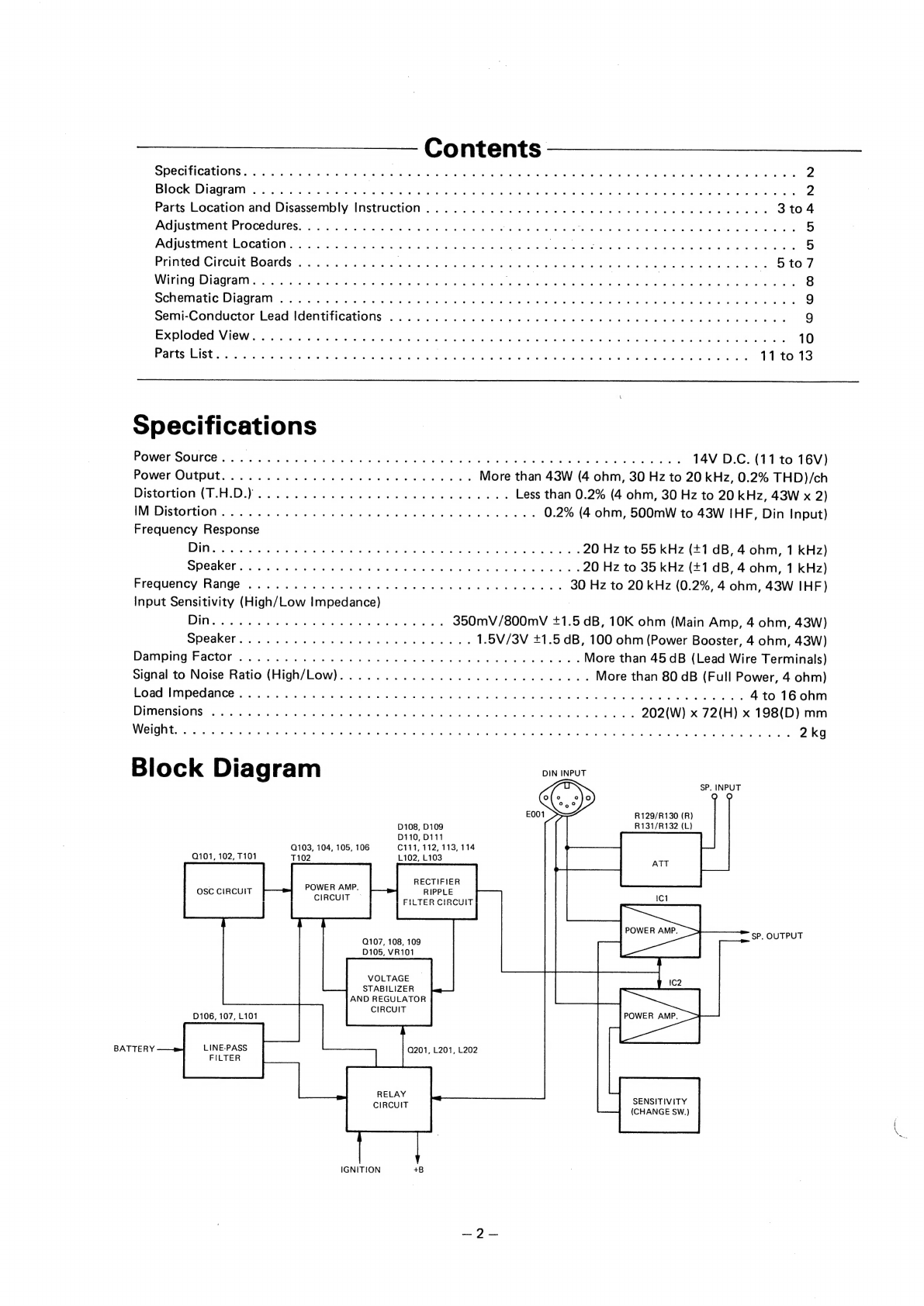
Block
Diagram
.............
sass
teste
eae
aise
ts
ecg
ees
to
stad
sls
Gg
en
ses
eat
2
Parts
Location
and
Disassembly
Instruction.
...........
0...
0c
eee
eee
eee
ee
eee
ee
eae
3
to
4
Adjustment
Procedures.................20
000s
Medak
ances
wees
PRG
ue
Gus
aie
Geen
Bak
a
ean
oe
5
Adjustment
Location...................0
0000
cies
Wie
einre
r
es
ee
che
oh
cae
ee
av
Sit
earn
et
ene
end
ate
5
Printed
Circuit
Boards
...........
Se
Be
ee
Bee
ee
Peeper
ee
ee
ww
Sit0
7
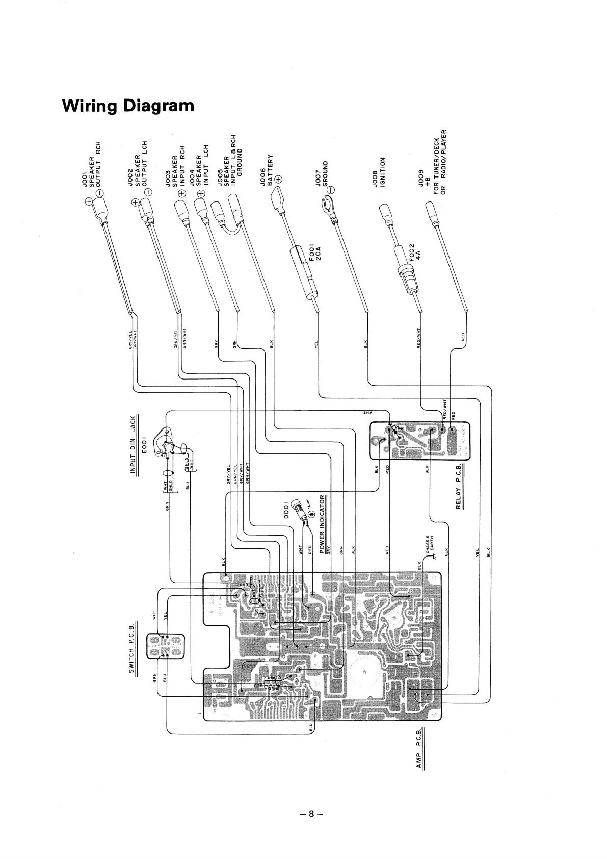
Wiring
Diagram...
2...
2.0.0.0...
0.0.02.
ee
eee
GUE
Rew
bes
te
et
eonee
are
fe
a
cits
dt
teks
oe
Goris
inch
ta
eek
8
schematic:
Didgraln-
e002
ae
es eh
oe
ek
A
ER
ee
ao
ae
eek
Be
ace
eke
w
bd
ea
oat
OS®
9
Semi-Conductor
Lead
Identifications
....
0...
00.
ee
ee
ee
ee
ee
ee
ene
9
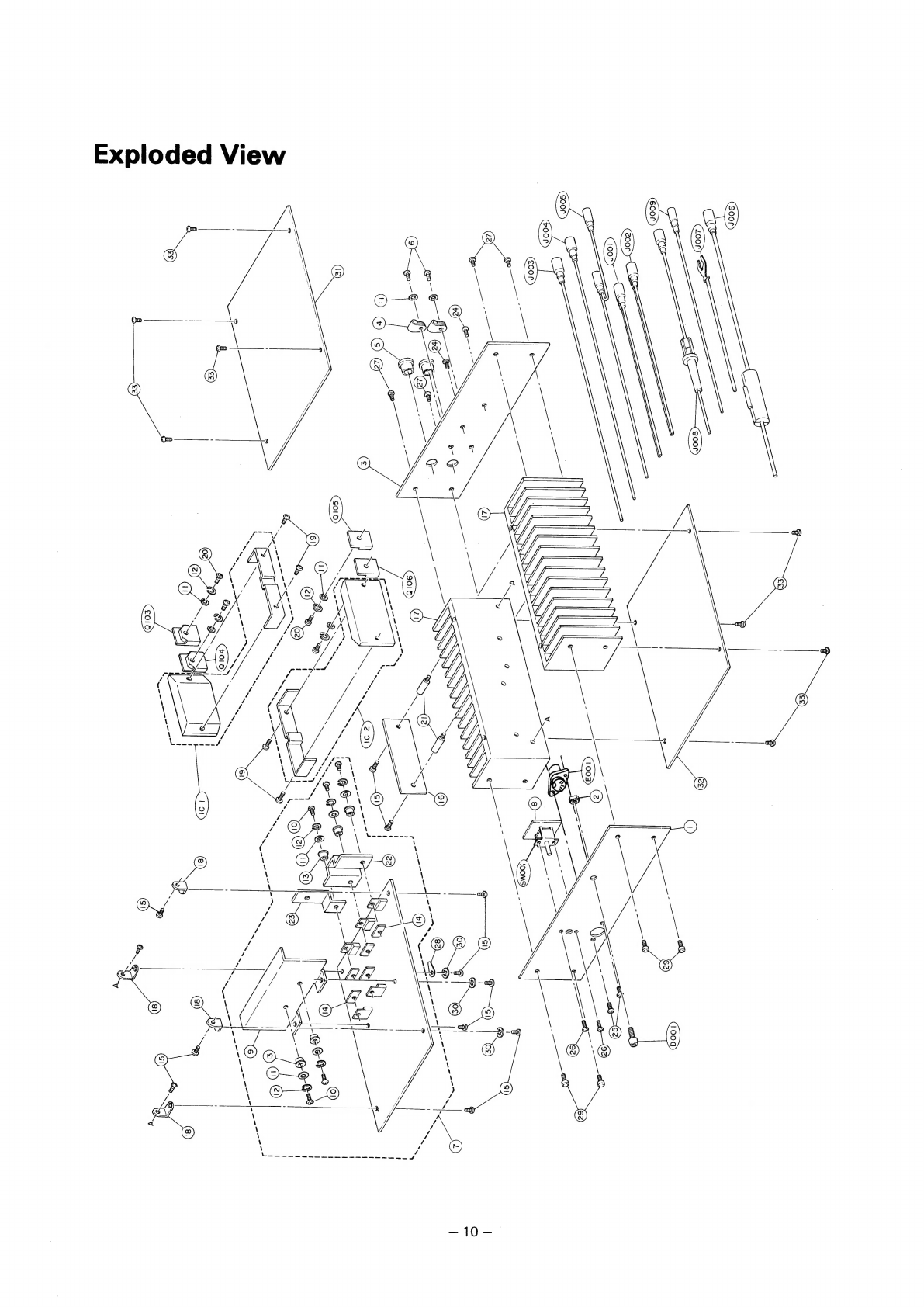
Exploded:
Views
<
4.4
4.sacteure
on
Ge
ee
ee
Ee
I
BAe
BR
0
oS
SS
hae
10
ARCS
VASE
a5:
sp.
ilaue
Goes,
ea
OS
ws
Oe
es
ae
fee
SL
Goes)
Gee
de
Me
Beas
sa
es
we,
Etc
aie
ote
ate
eS
ep
aes
es
11
to
13
Specifications
POWER
SOURCE
6
¢
8-6
veh
Okt
Gea
sees
cee
hash
ek
Som
eG
A
ele
set
en
sun
disiew
hlhl
6
eh
14V
D.C.
(11
to
16V)
Power
Output...
6
os
desk
bee
She
SA
ewe
aS
More
than
43W
(4
ohm,
30
Hz
to
20
kHz,
0.2%
THD)/ch
Distortion
EAD)
ecdch
ein
wal
Boe
we
dba
2
ed
ale
bo
ees
Less
than
0.2%
(4
ohm,
30
Hz
to
20
kHz,
43W
x
2)
IM
DDISTOMEIGN
40.0
3
4.
8
eot-ke
se
Gd
ei
ae
RS
ee
ee
ES
Wale
nd
0.2%
(4
ohm,
500mW
to
43W
IHF,
Din
Input)
Frequency
Response
ier
g
Geie
doe
aa
okt
ie
eee
te
a
A
ten
eS
ee
al
20
Hz
to
55
kHz
(+1
dB,
4
ohm,
1
kHz)
BDCaw
Ola
aut
Wise
bap
ina
att
oe
eee
ee
bas
acd
cane
ain
20
Hz
to
35
kHz
(+1
dB,
4
ohm,
1
kHz)
Frequency
Range
.........
0.0.00
c
ce
ee
eee
ee
ee
ee
eens
30
Hz
to
20
kHz
(0.2%,
4
ohm,
43W
IHF)
Input
Sensitivity
(High/Low
Impedance)
EVV
erie
tag
Ve
ras
cscs
chee
obs
See
En
Bk
Se
via
350mV/800mV
+1.5
dB,
10K
ohm
(Main
Amp,
4
ohm,
43W)
GOCAK
ED
i525
oc
ho
coe
hk
os
a
ane
ae
er
oe
1.5V/3V
+1.5
dB,
100
ohm
(Power
Booster,
4
ohm,
43W)
Damping
Factor
5-03.
%
doa owe
Be
ee
eee
be
Be
HB
bnew
See
More
than
45
dB
(Lead
Wire
Terminals)
Signal
to
Noise
Ratio
(High/Low).
...............
0.000
ee
eeae
More
than
80
dB
(Full
Power,
4
ohm)
LOad:
limped
anee
¢.i.
630
sip
Gok
ewan
eS
OS
ead
cs
bk
BOOS
EROS
ER
Rw
Me
eek
hte
4
to
16
0hm
ED
GVA
TSVOINS
sh
dees
chip,
Bess
Ne
Se
ses
rege
das daa
teks
ah
rca
te
enc
pc
sl
so
es
Se
See
San tbe les
helo
202(W)
x
72(H)
x
198(D)
mm
UCU
CIN
Ge
eM
esk,
Bt
ces
A,
Si
tay
A
Nee
tan
eg
Bd
gk
eh
nd
cy)
ase
ae
SOS
Bin
weerunticia
Ge
nda
ade
ieee
AAP
th
det
2
kg
Block
Diagram
DIN
INPUT
5
SP.
INPUT
O[
o
eo}o
O
O
hed
E001
R129/R130
(R)
D108,
D109
R131/R132
(L)
D110,
D111
Q103,
104,
105,
106
C111,
112, 113,
114
Q101,
102,
T101
T102
L102,
L103
RECTIFIER
RIPPLE
»
FILTER
CIRCUIT
POWER
AMP.
CIRCUIT
©
Q107,
108,
109
D105,
VR101
Mi
IC1
PONE
SP.
OUTPUT
_
mrs
POWER
AMP.
VOLTAGE
STABILIZER
AND
REGULATOR
CIRCUIT
/
D106,
107,
L101
\
BATTERY
LINE-PASS
Q201,
L201,
L202
FILTER
RELAY
CIRCUIT
SENSITIVITY
(CHANGE
SW.)
IGNITION
+B