manuals.online logo
Brands
  1. Home
  2. •
  3. Brands
  4. •
  5. Alpine
  6. •
  7. Amplifier
  8. •
  9. Alpine 3522S User manual

Alpine 3522S User manual

Other Alpine Amplifier manuals

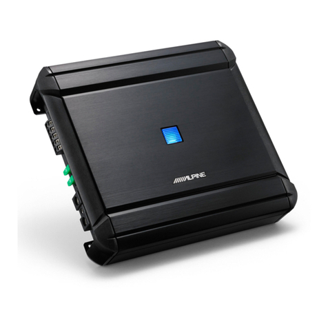
Alpine MRA-D550 - V12 Amplifier User manual

Alpine

Alpine MRA-D550 - V12 Amplifier User manual

Alpine KTA-30FW User manual

Alpine

Alpine KTA-30FW User manual

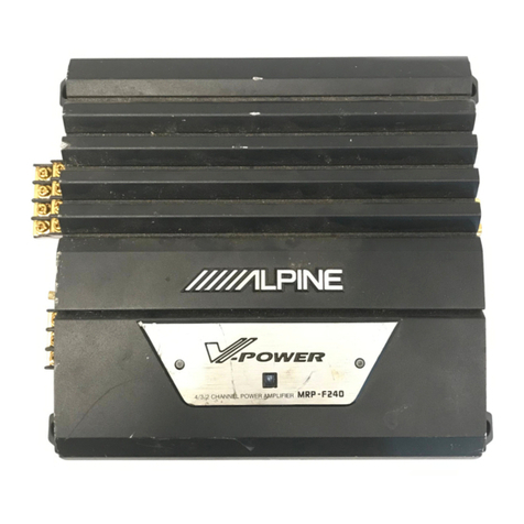
Alpine MRP-M450 User manual

Alpine

Alpine MRP-M450 User manual

Alpine MRP-M1000 - Amplifier User manual

Alpine

Alpine MRP-M1000 - Amplifier User manual

Alpine MRV-F900 - Amplifier User manual

Alpine

Alpine MRV-F900 - Amplifier User manual

Alpine MRP-F320 User manual

Alpine

Alpine MRP-F320 User manual

Alpine MRV-1507 User manual

Alpine

Alpine MRV-1507 User manual

Alpine MRD-M1001 User manual

Alpine

Alpine MRD-M1001 User manual

Alpine 3555 User manual

Alpine

Alpine 3555 User manual

Alpine PDX-2.150 User manual

Alpine

Alpine PDX-2.150 User manual

Alpine MRP-F300 User manual

Alpine

Alpine MRP-F300 User manual

Alpine PDR-M65 User manual

Alpine

Alpine PDR-M65 User manual

Alpine MRV-F300 User manual

Alpine

Alpine MRV-F300 User manual

Alpine PDR-V75 User manual

Alpine

Alpine PDR-V75 User manual

Alpine MRV-M250 User manual

Alpine

Alpine MRV-M250 User manual

Alpine PXE-M60-4 User manual

Alpine

Alpine PXE-M60-4 User manual

Alpine PDR-V75 User manual

Alpine

Alpine PDR-V75 User manual

Alpine MRV-100M User manual

Alpine

Alpine MRV-100M User manual

Alpine R2-A150M User manual

Alpine

Alpine R2-A150M User manual

Alpine PDX-M12GC User manual

Alpine

Alpine PDX-M12GC User manual

Alpine PXE-0850S User manual

Alpine

Alpine PXE-0850S User manual

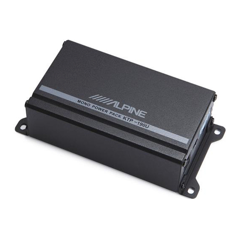
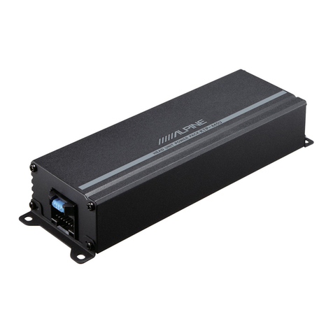
Alpine KTP-445U User manual

Alpine

Alpine KTP-445U User manual

Alpine MRV-F345 - V12 Car Amplifier User manual

Alpine

Alpine MRV-F345 - V12 Car Amplifier User manual

Alpine MRD-M1001 User manual

Alpine

Alpine MRD-M1001 User manual

Popular Amplifier manuals by other brands

Magnat Audio EDITION FOUR Owner's manual/warranty document

Magnat Audio

Magnat Audio EDITION FOUR Owner's manual/warranty document

Inter-m PA-2000A Operation manual

Inter-m

Inter-m PA-2000A Operation manual

Yamaha TX6n owner's manual

Yamaha

Yamaha TX6n owner's manual

Peavey TNT 150 user guide

Peavey

Peavey TNT 150 user guide

Bosch LBB 1903/10 Installation and user instructions

Bosch

Bosch LBB 1903/10 Installation and user instructions

Avocent Emerge DA1200D Installer/user guide

Avocent

Avocent Emerge DA1200D Installer/user guide

Redgum RGi35 operating instructions

Redgum

Redgum RGi35 operating instructions

Cambridge Audio AXA25 user manual

Cambridge Audio

Cambridge Audio AXA25 user manual

Technical Pro H1502UrBT user manual

Technical Pro

Technical Pro H1502UrBT user manual

FMS EMGZ307 operating manual

FMS

FMS EMGZ307 operating manual

Racal Instruments 5601 user manual

Racal Instruments

Racal Instruments 5601 user manual

Valcom V-1094A Technical specifications

Valcom

Valcom V-1094A Technical specifications

Cambridge Audio 851D user manual

Cambridge Audio

Cambridge Audio 851D user manual

QSC 3800 Specifications

QSC

QSC 3800 Specifications

NAD C300 owner's manual

NAD

NAD C300 owner's manual

Rotel RMB-1077 owner's manual

Rotel

Rotel RMB-1077 owner's manual

Peavey Monitor 300 Series operating guide

Peavey

Peavey Monitor 300 Series operating guide

Crown XTi 1002 Specifications

Crown

Crown XTi 1002 Specifications

manuals.online logo
manuals.online logoBrands
  • About & Mission
  • Contact us
  • Privacy Policy
  • Terms and Conditions

Copyright 2025 Manuals.Online. All Rights Reserved.

JMNLPINE.
cic
MANUAL
Bridgeable
Power
Amplifier
SOEARRES|
2
_
E
ea
ve
peat
3522S
|
Contents
Specifications
2/5
eis
s
ok
aus
wire
pede
aes
po
Oe
Wa
oa
OB
SHE
Ee
eee
oe
det
tesantien
Mat
Md
Mabk
eed
O80
Be
ec
eensee
3
FOOT
OS?
xc.
Sse
Br
a
Suda
sees
pate
Ses
oa
eee
Tate
dei
Son
GGUS
arte
ae
te
aac
ata
heat
ae
eves
at
tte
ea
ace
eich
Bienen
tear
ah
ate
nae
aeons
we
4to5
Switches
and
TerminalS
icc...
oss
asad
eeced
dwearee
Biwi
a
de
adie
a
hep
pre
re
Pee
hands
2b
Mie
GRAMS
ye
Sealed
Eee
6
Connections
...........
ese
ert
eibathe
Seats
pants
Ue
te
ateet
taelnad
ee
aaa
da
sees
Son
rae
el
Ee
6
to
9
SWitch
SettingS.4.i3-.2
inhi
tee
ae
eee
Nhe
a
teed
tga
a
eee
rardan
tee
eauntiged
4
hele
aageeieg
9
to
10
Characteristic
Curves:
aicacs
ae
ine
ca
ke
ee
ie
he
area
ted
Siel
neo
RR
Ne
Stee
aa ae
a
aa
a
we
a
id
ne
ee
ee
ed
11
eR
De
2
ERD
AMC
eee
Poa
thuttah
tre
eatin
Cepek
ctekca
Net
ene
ata
cater
yc
ts
Wien
u
tem
oa
Rice
12
Me
Ii
arnt
ede
eiecin
args
Eeranih
sud
Oe
ix
A
9b
SGN
BS
Had
BI
IRGS
ine
RA
ae
Maton
eae
WN
Te
Ge
also
aa
5
12
Pe
EVD
FAD
co
slips
woh
o
Melee
ge
ORES
deta
ete
We
dine
Cease
Menge
ewaaleer
ude
ts
LINE
grees
ees
13
TN
fateh
cae
Rieti
aU
nts
lata
Gla
ttde
Nita
cette
tel
Ooo
aa!
ote
ils
fare
hed
Ata
gat
nen
tat
A
nid
a
ded
ala
14
Pel
E
oe
sp
oeln
oe
ee
asize
At
eee
ath
atid
caclceaksed
aid
ta
Ue
dtnih
am
tah tate
ok
Wi
DU
ti
ela
alta
cae
15
NPS
es
Nc
Sehr
tah
knelate
gi
dished
es
dicta
fee
eee
we
se
We
eed
htaks
nacicna
ee
emcee
ete
Lace
15
Block:
Diagram:
<scavcwakmekt
Geek
i
eta
wept
ee
eee
oleae
tee
bP ea
Sig dee
Bat
Pasha
ae
ees
ah
ereow
Vinee
Grated
aca
Reha
17
Parts
Layout
on
P.C.
Boards
and
Wiring
Diagram
.....
6...
nett
ete
19
to
21
Schematic
Diagrams
vasa
Mae
wee
eee
a
tee
ee
oe
he
ye
Gea
eoces
hn
8
54
Ga
ee
oe
pI
aed
22
to
24
Electrical-Parts:
List’
264
¢
soe
we
oS
Rete
we
San
ue
eae
Mae
Gh
ed
ee
AAS
wae
aie
eh
a
eae
25
to
27
Cabinet
Assembly
Parts
List
2...
0...
ec
ec
eee
ee
ene
een
ene
e
ete
eens
28
Exploded
View
(Cabinet)
2.0.0.0...
cc
ccc
ccc
cece
ee
eee
e
eee
eee
e
tenn
eee
e
bette
eee
e
nes
29
to
30
Packing
Assembly
Parts
List...
6...
ccc
eee
eee
eee
eee
nen
ees
31
Packing
Method
View
..........
cece
ccc
cece
cece
eee
eee
ne
ee
nett
eaten
tee
e
ene
enna
eens
tetnees
31
Semi-Conductor
Lead
Identifications
.....
0...
een
ent
eee
e
nee
nnn
ee
ere
32
Additional
Schematic
Diagram
Inserted.
ei
te
tt
tt
‘
1
t
sl
:
f
4
|
3522S
Specifications
POWErSOULCE
diciie
sidcers,
Sodas
Raeeho
te
NEG
Sis
SP
ORNS
SoS
Aree
OE
RISES
OE
ES
Dao
R a
atiate
Sana
gia
eA
Eggs
FS.
ase
14.4V
DC
POWEr
OQULPULS
Sedce
cagteua
eae
ce
ook
ne
sbae
niin
ee
etataa
eee
ee
gees
4
ohm
2-Channel
(at
0.08%
T.H.D.)
:
25W/ch
(at
10%
T.H.D.):
35W/ch
2
ohm
2-Channel
(at
0.8%
T.H.D.)
:
30W/ch
(at
10%
T.H.D.)
:
40W/ch
4
ohm
BTL
mode
(at
0.8%
T.H.D.)
:
65W/ch
Input
Sensitivity
(at
30W/ch
Output)
...
20.0...
teen
nents
Speaker
Input
:
2V+2dB
RCA
Input
:
0.5V+2dB
Input
IMpEdaNnce:
sscscudeee
awe
dd
ahee
ob
velar
ete
eek
See
Oe
edi
alle
te
Pea
daida
eeeWae
rae
eee
eae
10£2k
ohm
Frequency
Range
(at
1KHZ41dB)
2.0.0...
ccc
eee
eee
ene
nett
eer
eee
nent
eben
ences
20Hz~40kHz
Channel
Separation
(Input
shorted,
at
D2)
oc
siete
deeds
hen
ea
oon
te
a
be
tainhcem
aa
dts
nda
eeus
55dB
S/N
Ratio
(Output
30W/ch,
Input
shorted)
00.0.6.
nnn
tte
tne
e
een
enn
tees
90dB
Residual
Noise
(Input
shorted,
4
ohm
2-channel)
.......
0.0
cece
cence
eee
eee
ene
eee
e
nee
1.2mV
Current:
Drain:
(at:
10%
TeHi
Dd!
s.2
52h
cata
enks
CAS
bin
ele
Heese
Sete
te
eae
RiwE
eee
Re
Ne
ee
4
ohm
2-Channel:
15A
2
ohm
2-Channel
:
20A
FUSE.
028
edict
dale
phcae
ad
Satin
anes
tet
ei
Gies
ele
eons
len
ea
ho
ndeck,
be
he
awtne
duals
gdlea
TRL
Rah
G
oF
15A
(Battery)
SEMICONAUCOMS:
cs:nc
er
ensetekstane
de
th
men
a
seed
cae
aw
eo
8IC’s,
25
Transistors,
2
FET’s,
13
Diodes,
4
Zener
Diodes
Dimensions:
(WICH
XD)
iccic.
8
cecscttee
Gbeacdes
Ha
Sats
ta
Roeede
de
Rho
tae
ch
ena
bee
Pea
a
Rigiee
tees
dau
Sauk
ete
22030
130mm
Weight):
s.ever
as
eaiie
oB
hea
ncigh
Abs
seen
ute
Pe
gine
dada
ting
ch
Rae
Cate
oadige
Rae
ete
Cae
E
dasa
gS
1.22kg
Note
:
Due
to
continuing
product
improvement,
specifications
and
design
are
subject
to
change
without
notice.
FEATURES
|
2/1
CHANNEL
OPERATION
The
3522S
can
be
used
as:
a.
2-channel
amplifier,
producing
30W
per
channel
into
4
Q,
or
40W
per
channel
into
2
Q.
b.
1-channel
amplifier,
producing
80
W
per
channel
into
4
Q.
MULTIMODE
CAPABILITY
Multimode
capability
allows
the
3522S
to
operate
in
its
2-channel
stereo,
and
bridged
mono
modes
simultaneously.
This-way,
the
amplifier
can
power
a
pair
of
satellite
speakers,
along
with
a
bridged
mono
subwoofer,
and/or
a
true
center
channel
speaker.
3,
2,
OR
1
CHANNEL
OPERATION
Thanks
to
its
Multimode
capability,
the
3522S
can
simultaneously
drive
a
pair
of
satellite
speakers
in
stereo,
along
with
a
bridged
mono
subwoofer
(and/or
center
channel
speaker)
for
a
total
of
3
channels.
In
addition
to
Multimode,
the
3522S
can
be
driven
in
a
conventional
2-channel
mode,
or
its
two
channels
can
be
bridged
into
a
single
channel
of
considerably
higher
power
output.
ACTIVE
DIVIDING
NETWORK
A
built-in,
switchable
electronic
crossover
network
at
80
Hz,
18
dB
per
octave,
can
be
used
to
set
up
the
amplifier
for
low-pass
(subwoofer)
or
high-pass
(tweeter/midrange
satellite)
applications.
This
network
can
also
be
switched
off
to
allow
full-range
signal
amplification.
DUO-B
FEEDBACK
CIRCUITRY
This
stabilizes
the
amplifier,
removes
DC
offset,
and
offers
excellent
total
harmonic
distortion
(T.H.D.)
characteristics.
It
also
provides
low
T.1.M.,
excellent
slew
factor,
stability,
and
musicality.
NO
CURRENT
LIMITING
Absence
of
current
limiters
in
the
audio
section
ensures
low
T.1.M.,
excellent
transient
response,
and
superb
sonic
quality.
S.T.A.R.
CIRCUITRY
The
Alpine-developed
Signal
Transit
for
Accurate
Response
circuit
topology
improves
sonic
properties
by
reducing
interaction
between
different
sections
of
the
circuitry.
INPUT
MODE
SELECTOR
This
switch
allows
the
user
to
specify
the
input
signal
entering
the
ampli-
fier.
Among
other
benefits,
it
eliminates
the
need
for
RCA-type
Y-
adaptors
when
bridging
the
amplifier.
DC-TO-DC
SWITCHING
MODE
POWER
SUPPLY
Provides
excellent
power
output
throughout
the
audio
bandwidth
20
Hz
to
20
kHz.
Its
soft
clipping
characteristics
ensure
superb
transient
response
and
musicality.
EXTRA
HEAVY
DUTY
CONSTRUCTION
SPEAKER
LEVEL
INPUT
CAPABILITY
FULLY
DISCRETE,
COMPLEMENTARY
OUTPUT
CIRCUITRY
GOLD-PLATED,
SCREW-DOWN
POWER
AND
SPEAKER
TERMINALS
INDEPENDENT,
CONTINUOUSLY
ADJUSTABLE
GAIN
CONTROL
HIGH
PERFORMANCE,
LOW
NOISE,
AUDIOPHILE
QUALITY
ACTIVE
AND
PASSIVE
COMPONENTS
VOLTAGE
REGULATED/FILTERED
INPUT
STAGES
GOLD-PLATED
RCA
INPUT
CONNECTORS
THIRD-ORDER,
(18
dB
PER
OCTAVE)
CAPACITIVE/INDUCTIVE
POWER
SUPPLY
INPUT
AND
OUTPUT
FILTERING
STATUS
MONITOR
This
indicator
illuminates
in
green
when
the
amplifier
is
on
and
opera-
tional.
This
light
will
turn
orange
if
any
internal
protection
circuitry
is
activated.
in
case
of
an
installation
problem,
the
STATUS
MONITOR
can
aid
jn
troubleshooting
the
system.
SWITCHES
AND
TERMINALS
BPBSOQOQLVOOHOHO
Status
Monitor
Input
Gain
Adjustment
Control
Active
Dividing
Network
Mode
Selector
Switch
Input
Mode
Selector
Switch
RCA
Input
Connectors
Speaker
Input
Connector
Speaker
Output
Terminals
Fuse
(15A)
Battery
Lead
Terminal
Remote
Turn-On
Lead
Terminal
Ground
Lead
Terminal
(ofo)
Neg
ates
Before
making
connections,
be
sure
to
turn
the
power
off
to
all
audio
components.
Insulation
tubes
for
the
speaker
terminals
and
the
power
supply
terminals
are
supplied
with
the
3522S.
Make
sure
the
speaker
leads
and
power
supply
leads
are
routed
through
these
tubes
separately
before
making
final
connections.
CAUTION:
Always
keep
the
RCA
inputs
of
the
3522S
connected
to
a
signal
source
while
the
amplifier
is
in
operation.
@
Speaker
Output
Terminals
The
3522S
has
a
set
of
speaker
outputs.
Be
sure
to
observe
correct
speaker
output
polarity
and
phasing.
In
the
stereo
mode,
connect
the
left
and
right
speaker
outputs
to
their
respective
speakers.
Connect
the
positive
output
to
the
positive
speaker
terminal
and
the
negative
to
negative.
In
the
bridged
mode,
the
left
positive
output
is
connected
to
the
positive
terminal
of
the
speaker
and
the
right-negative
output
is
con-
nected
to
the
negative
terminal
of
the
speaker.
Do
not
use
the
negative
(-)
speaker
output
as
a
common
output
for
left
and
right
speakers.
Do
not
connect
the
speaker
outputs
to
the
vehicle's
chassis.
CAUTION:
Do
not
connect
speaker
leads
together
or
to
chassis
ground.
@
Speaker
Input
Leads
These
leads
are
input
leads
for
use
with
head
units
not
equipped
with
preamp
outputs.
When
not
using
the
RCA
Line
Input
connectors,
you
should
connect
these
wires
to
the
speaker
output
leads
of
your
head
unit.
The
3522S
accepts
input
from
high
power
or
standard
power
head
units.
®
RCA
input
Connectors
Connect
these
connectors
to
the
line
out
leads
on
your
head
unit
using
RCA
extension
cables
(sold
separately).
Be
sure
to
observe
correct
channel
connections;
Left
to
Left
and
Right
to
Right,
Front
to-Front
and
Rear
to
Rear.
@
Battery
Lead
(Yellow)
Connect
this
lead
directly
to
the
positive
(+)
terminal
of
the
vehicle's
battery.
Do
not
connect
this
lead
to
wiring
in
the
vehicle's
electrical
system.
Be
sure
to
add
a
25A
in-line
fuse
amp
as
close
as
possible
to
the
battery's
positive
(+)
terminal.
This
fuse
will
protect
your
vehicle's
electri-
cal
system
in
case
of
a
short
circuit.
If
you
need
to
extend
this
lead,
the
wire
gauge
should
be
10
AWG
or
larger.
.
SWITCHES
AND
TERMINALS
OO®d
®
cee
a.
©
O¢
0
»
[tet
Tel
et
teal]
|
(etal
s——
©
aes
@
os
?
oa
=
=
PSBOSOOPOOHHOHO
MUNPINE
as2zs,
FOE
ABLE
POWER
ane
CR
SO
©
©
i
egestas
al
Ea
ea
Ee
Maniyaaiiaainl
O
Status
Monitor
Input
Gain
Adjustment
Control
Active
Dividing
Network
Mode
Selector
Switch
Input
Mode
Selector
Switch
RCA
input
Connectors
Speaker
Input
Connector
Speaker
Output
Terminals
Fuse
(15A)
Battery
Lead
Terminal
Remote
Turn-On
Lead
Terminal
Ground
Lead
Terminal
CONNECTIONS
Before
making
connections,
be
sure
to
turn
the
power
off
to
all
audio
components.
Insulation
tubes
for
the
speaker
terminals
and
the
power
supply
terminals
are
supplied
with
the
3522S.
Make
sure
the
speaker
leads
and
power
supply
leads
are
routed
through
these
tubes
separately
before
making
final
connections.
CAUTION:
Always
keep
the
RCA
inputs
of
the
3522S
connected
to
a
signal
source
while
the
amplifier
is
in
operation.
@
Speaker
Output
Terminals
The
3522S
has
a
set
of
speaker
outputs.
Be
sure
to
observe
correct
speaker
output
polarity
and
phasing.
In
the
stereo
mode,
connect
the
left
and
right
speaker
outputs
to
their
respective
speakers.
Connect
the
positive
output
to
the
positive
speaker
terminal
and
the
negative
to
negative.
In
the
bridged
mode,
the
left
positive
output
is
connected
to
the
positive
terminal
of
the
speaker
and
the
right-negative
output
is
con-
nected
to
the
negative
terminal
of
the
speaker.
Do
not
use
the
negative
(~)
speaker
output
as
a
common
output
for
left
and
right
speakers.
Do
not
connect
the
speaker
outputs
to
the
vehicle's
chassis.
CAUTION:
Do
not
connect
speaker
leads
together
or
to
chassis
soured
@
Speaker
Input
Leads
These
leads
are
input
leads
for
use
with
head
units
not
equipped
with
preamp
outputs.
When
not
using
the
RCA
Line
Input
connectors,
you
should
connect
these
wires
to
the
speaker
output
leads
of
your
head
unit.
The
3522S
accepts
input
from
high
power
or
standard
power
head
units.
@
RCA
Input
Connectors
Connect
these
connectors
to
the
line
will
leads
on
your
head
unit
using
RCA
extension
cables
(sold
separately).
Be
sure
to
observe
correct
channel
connections;
Left
to
Left
and
Right
to
Right,
Front
to
Front
and
Rear
to
Rear.
@
Battery
Lead
(Yellow)
Connect
this
lead
directly
to
the
positive
(+)
terminal
of
the
vehicle's
battery.
Do
not
connect
this
lead
to
wiring
in
the
vehicle's
electrical
system.
Be
sure
to
add
a
25A
in-line
fuse
amp
as
close
as
possible
to
the
battery's
positive
(+)
terminal.
This
fuse
will
protect
your
vehicle's
electri-
cal
system
in
case
of
a
short
circuit.
If
you
need
to
extend
this
lead,
the
wire
gauge
should
be
10
AWG
or
larger.
CONNECTIONS
©
RCA
Input
Connectors
Let
©
(White)
Speaker
©
(White/Black)
Right
©
(Gray)
Speaker
@
Speaker
Input
Leads
©
(Gray/Black)
@
Battery
Lead
(Yellow)
©
Remote
Turn-On
Lead
(Blue/White)
©
Ground
Lead
(Black)
©
Remote
Turn-On
Lead
(Blue/White)
Connect
this
lead
to
the
remote
turn-on
or
power
antenna
(positive
trigger,
(+)
12V
only)
lead
of
your
head
unit.
@
Ground
Lead
(Black)
Connect
this
lead
to
a
clean,
bare
metal
spot
on
the
vehicle's
chassis.
Verify
this
point
to
be
a
true
ground
by
checking
for
continuity
between
that
point
and
the
negative
(—)
terminal
of
the
vehicle's
battery.
Ground
all
your
audio
components
to
the
same
point
on
the
chassis
to
prevent
ground
loops.
@
Insulation
Tube
Use
these
tubes
to
cover
the
power
and
speaker
terminals
after
connec-
tions
have
been
made.
This
will
prevent
inadvertent
shorting
of
the
terminals.
@
insulation
Tube
SEH
|
3522S
ST
TYRES
AE
OS
RRCAESSP
i
i
i
i
i
i
i
a
i
'
i]
é
i
IE
EME
YO
SES
I
TPES
OCI
IEE
SSE
PACT
LESS
POSER
STS
‘-rcunarmcmntrntntat
més
rR
IR
PHEASANTS
i
CORPO
3522S
|
“2.
CONNECTIONS
Please
check
your
head
unit
for
the
conditions
listed
below:
a.
The
head
unit
does
not
have
a
remote
turn-on
or
power
antenna
lead.
b.
The
head
unit's
power
antenna
lead
is
activated
only
when
the
radio
is
on
(turns
off
in
the
tape
or
CD
Mode).
.
The
head
unit's
power
antenna
lead
is
logic
level
output
(4)
5V,
negative
trigger
(grounding
type),
or
cannot
sustain
(+)
12V
when
connected
to
other
equipment
in
addition
to
the
vehicle’s
power
antenna.
If
any
of
the
above
conditions
exist,
the
remote
turn-on
lead
of
your
3522S
must
be
connected
to
a
switched
power
source
(igni-
tion)
in
the
vehicle.
Be
sure
to
use
a
3A
fuse
as
close
as
possible
to
this
ignition
tap.
Using
this
connection
method,
the
3522S
will
turn
on
and
stay
on
as
long
as
the
ignition
switch
is
on.
*
If
this
is
objectionable,
an
SPST
(Single
Pole,
Single
Throw)
switch,
in
addition
to.the
3A
fuse
mentioned
above,
may
be
installed
in-line
on
the
35225
turn-on
lead.
This
switch
will
then
be
used
to
turn
on
(and
off)
the
3522S.
Therefore,
the
switch
should
be
mounted
so
that
it
is
accessible
by
the
driver.
Make
sure
the
switch
is
turned
off
when
the
vehicle
is
not
running.
Otherwise,
if
the
amplifier
is
left
on
for
an
extended
period
of
time,
the
car's
battery
may
be
drained.
eed
(Blue/White)
ruse
(24)
ignition
|
l
Source
Power
|
As
close
as
ev
Antenna
SPST
Switch
eee
is
tional)
yee
(op
ignition
tap
Remote
On
To
other
Alpine
components’
Remote
On
leads
“CONNECTIONS.
2-Channel
Stereo
System
(Full
Range,
Tweeter/Midrange
Satellite,
or
Subwoofer)
Position
of
the
Position
of
the
input
Filter
Switch:
Mode
Selector
Switch:
@
Full
Range
®©
Tweeter/Midrange
Satellite
(MONO)
ST
CHi)+@)
@
Subwoofer
Position
of
the
*
Position
of
the
Input
Filter
Switch:
Mode
Selector
Switch:
CHO}MONO)
ST
CHG)-(2)
Single
Channel
System
(Full
Range,
Midrange
Satellite)
Position
of
the
*
Position
of
the
Input
Filter
Switch:
Mode
Selector
Switch:
1(MONO)
@
Full
Range
[a_]
ra]!
ease
|
CHOKMONO)
st
cHO}E
@
Midrange
Satellite
CHOMONO)
ST
CHOM+2)
|
3522S
3522S
|
Input
Mode
Selector
Switch
a)
Select
the
“ST”
position
(center)
when
the
Left
(CH
1)
and
Right
|
channels
are
used
in
stereo.
es
CH{T}(MONO)
ST
CH{[i]+
b)
Select
the
“{1]
(MONO)”
position
when
only
one
channel
(Left
or
will
be
used
for
both
outputs
of
a
stereo
system
or
the
mono
out
bridged
system.
1
CH[I}(MONO)
ST
CHE)
+[2]
c)
Select
the
‘[1]
+
[2]”
position
when
the
Left
(CH
1)
and
Right
(Cr
channels
will
be
summed
for
a
subwoofer
system.
-T
CH[i](MONO)
ST
CHE)+E2]
Input
Gain
Adjustment
Control
After
setting
your
head
unit's
volume
control
1/4
of
a
turn
down
f
maximum
output
level,
rotate
the
Input
Gain
Adjustment
Control
wit
flat
blade
screwdriver
and
adjust
the
input
gain
to
the
point
where
tt
maximum
volume
with
no
distortion.
2-Channel
Stereo
System
(Full
Range,
Tweeter/Midrange
Satellite,
or
Subwoofer)
Position
of
the
Position
of
the
Input
Filter
Switch:
Mode
Selector
Switch:
@
Full
Range
®
Tweeter/Midrange
ST
Satellite
CH(](MONO)
ST
CHL]
®
Subwoofer
‘
Position
of
the
*
Position
of
the
Input
Filter
Switch:
Mode
Selector
Switch:
Subwoofer
Single
Channel
System
(Full
Range,
Midrange
Satellite)
Position
of
the
*
Position
of
the
input
Filter
Switch:
Mode
Selector
Switch:
1(MONO)
ayes
CHE(MONO)
ST
CHO]
ations
‘dr
:
®
Midrange
Satellite
aah
fe
ag
lf
eS
OFF
HP
uP
CHE(MONO)
ST
CHE}
@®
Full
Range
|
35228
=
3352.28
|
SWITCH
SETTINGS
~—
Input
Mode
Selector
Switch
a)
Select
the
“ST”
position
(center)
when
the
Left
(CH
1)
and
Right
(CH
2)
channels
are
used
in
stereo.
el
ie
CH
[i]
(MONO)
ST
CHE}
+2]
b)
Select
the
“{1]
(MONO)”
position
when
only
one
channel
(Left
or
Right)
will
be
used
for
both
outputs
of
a
stereo
system
or
the
mono
output
of
a
bridged
system.
To
CH[T](MONO)
ST
CH[i]+2]
c)
Select
the
‘{1]
+
[2]”
position
when
the
Left
(CH
1)
and
Right
(CH
2)
-
channels
will
be
summed
for
a
subwoofer
system.
{
-—
|
—
CH(AJ(MONO)
ST
CH{t]+{2]
Input
Gain
Adjustment
Control
After
setting
your
head
unit's
volume
control
1/4
of
a
turn
down
from
the
maximum
output
level,
rotate
the
Input
Gain
Adjustment
Control
with
a
#0
flat
blade
screwdriver
and
adjust
the
input
gain
to
the
point
where
there
is
maximum
volume
with
no
distortion.
"SWITCH
SETTINGS
Active
Dividing
Network
Mode
Selector
Switch
a)
Select
the
“LP”
position
when
the
amplifier
is
used
for
the
low-pass
(subwoofer)
system.
The
frequencies
higher
than
80
Hz
will
be
cut
(ata
rate
of
18
dB
per
octave).
a
OFF
HP
LP
b)
Select
the
“HP”
position
when
the
3522S
is
used
for
the
high-pass
(tweeter/midrange)
system.
The
frequencies
lower
than
80
Hz
will
be
cut
(at a
rate
of
18
dB
per
octave).
L—
PLP
L
+
mm
OF
c)
Select
the
“OFF”
position
when
the
3522S
is
used
for
the
regular
stereo.
system
with
full-range
speakers.
The
full
bandwidth
will
be
output
without
cutting
the
high
or
low
frequencies
eee
3
OFF
HP
LP
Status
Monitor
This
indicator
lights
in
green
when
the
power
is
on.
The
3522S
has
built-
in
protection
circuitry.
If,
for
some
reason,
this
protection
circuit
is
activated,
the
indicator
turns
orange.
If
this
happens,
turn
the
system
off,
find
the
cause
of
the
problem
and
remedy
the
situation.
This
includes
checking
all
your
connections
and
wiring.
If
the
indicator
remains
Orange
when
the
system
is
turned
on,
consult
your
authorized
Alpine
dealer.
NOTE:
The
indicator
will
illuminate
in
orange
for
a
few
seconds
when
the
power
is
turned
on
as
the
turn
on
muting
circuit
is
activated.
This
is
normal.
+10—
CHARACTERISTIC
CURVE
POWER
V.S.
DISTORTION
CURVE
OUTPUT
POWER
(W)
FREQUENCY
RESPONSE
CURVE
TTT
oom
Pt
TT
ee
He
RESPONSE
(dB)
1020
50
100
200 500
IK
2
OK
=.
20K
50K
100K
FREQUENCY
(Hz)
44S
Mh
pv7e---?
EROAIC
i
ee
ee
ETT
th
RES
APH
BUTRECMEZSCEMOVET,
GARB
SACtS-EF
ty
OLTH
ELED.
BM.
SEDCLLBFANTHSZENSULOTS
ff
#
mR
a
|
i
a
HELL.
AYR
+
LIyhOBRARADT
AVR
+
Do
yKOBREANS.
TEL,
eR
YI
—9
_|
BRILL.
||
P—-2-U-KBOREDARS,
P—RA-
U-KROHREERTS,
oRHOBERI
Y
ie
oe
YI—9—BBA
|
Ny
FU—-BRU-KROBRAR
|
Ny
FU—-BRU-KRORREE
SS.
zs,
RIS.
eka—xpINS
||L_*
:
4
TE
CORK.
ba-AAWNT
US.
PESBOLA-XERATS,
UEK+
AY
+
U-K
ROA
|
UE-K-
ay
-
U-KBORBE
KB.
HBTS,
_|
RE-ADIVE-YYREPYI
|
RE—N-
FV
E-PURRBRT
|
MAAS
TEL,
Bo
—f
RE—ARRND
A-—KUTLIS,
AE-ARRERIATS.
ROY
A-KL
@
CARE
RAT
VAT
ALSNETEUMIBICS
Bo
INPUT
tiFICIEL<ATS.
AU—ARRORREERI
3,
VAT
ACSEDNETEUMBCT
Do
BRLASA.
BAH
TEL
ANE-KRUOBAT
VY
FMB
R
AF
LICE
DTU
PINAI-KOBRARRS,
AUE—ARRN
KEL.
AD
BEBERU
2-LWBRYATF
SISHGITUEL.
REOMEZS
CES
THBSBUCES,
SRULTEREASE<OY-ER-YaVT,
PINT
YH
EAA
YIAX-YaY-
RYI-(
SRO
V-ER-Y
ay
IOTRA
HSB)
COMA
ERL
@rruy4
TD
F4
NAF
4
Va-RY
KD-—J
AR
I8dB/oct.
RA
—-
TORENT
IF
4
TF
4
NFAT
RY
KOK
De
Aifie
O-NAGII-N-)
P/V
NACY
4
-B/EY
ELL
A)
MAP
MMORU
BSCE
TE
BOCVUF-
URFLPITY
DN
VAT
bGERREL
A2FLERRT
SOL
BHT,
@DU0-8
(Fa7-NK—4)
IB
f+
ik
i
OW
ILNFBEL
¢
IR
HODCH—KEBO
2
DERI
HAD
SHMIC
DIENT
ZDENKBECERILELK,
@STARY—+y
KR
EFORNOPBERS
LL.
AL-AGNERRL
ANS
0
CE
HE
(CLS
P
ILINT
DE
OSTARY—+
y
KERALELK,
COMMICEU,
SNE
HOMMEEMLACELK,
@AHE-KWOPARHL
YF
COAT
YF
ODYUDAICHL
UMBORFLATOMAOARS
TT
Jy
AES
ETH
FIO—-N—-WP
LOE
LCD
SES
BRY
AF
LHR
TET.
OAABERERU
a—Ly
OSRREOB
(RIM
VUT—S—H)
FeIREI],
ACM
CHEHIU
TSU,
RIMIIIZ
ADE
oH
ee
Ce,
AMOR
ERMC.
SMC
RHEL
Py
RODD
UM
BE
PUES,
@2E-AAH
WAPINIZI9—1'RUFa—t—-
AYR
-
IL-vteaee
AAU-hREROCTHEMETUD
FEBRLALEKUET,
ee,
Fee
NIE
?
EAD
BIC
PLC
CMBR
OSCCMHVET,
(EREKMS
SHICLSO-BFLIvOLTH
}
BeotLEBFANTHSCEMBUEDNTT.
Mh
iz
“|
ia
TEL
Ne
mt
Y
~
Da
tt
WINS
so
LEITBESBUCES,
SRULTBRKSBECOV-ER-
Vay,
PINT
Yo
Ay
+
LIyROBRRADTL
TSLNo
AvkK+
ADyhOBRBZANS.
ican
A+
U-BRORME
REE.
PAs
U-RRORREIERT
So
Ny
FT
U~BIRU
—
KOR
RAK
.
RB.
CKI-ABWNT
Do
eon
EES
a
Ky
FU-BRU-K
ROR
IE
B29
Do
MPESBOLAI-XERIETS,
UE-K
+
AY
+
U-KROBRA
REZ
DEK
AY
U-KRORRE
HERTS.
|
AE-ADAVE-FVYREPYI
HAMS
TUE.
AG-A
+4
YVE-FPYARERT
AL—ARAY
A—-KUTIS,
At—
NECRERIRT
So
4
ADE-KIBAT
YFMBNY
A
AE-HERPAES.
ANBEBBRY
2~LMBRUAT
AIZTHD
TLV.
AT
LICBDTlVEL
o
Bo
P
|INA-KOBRRAREL.
INPUT
tm
FIZIEL<
ATS.
VAT
ACEDETEUMTEICT
RU-ARROBREELST
S,
YVAFAICSPETELLMWUBICT
Bo
~YEYRYI-—(SROU-EA-YEaYIDOCRA
ESB)
IC
TBR
EA
OPOF
AD
TANNA
FAVI-AYARD-—IAR
18dB/oct.
LOA—-TORBHIP
ITF
147
F
4
NA
FAL
TRY
bh
DR
DEAR.
A-NAGTI-N-)PIM
NACI
4
—S/E
9
ELE
VY)
HAD
BCU
ET
CER
TE
SDCVLFE
VRFLODVID
A
DAF
LECMERU
AT
LEERI
SOIC
EHTT.
@0U0-8
(F27-N—Y)
OB
Fp
+
Bed
Adi
at
NFBEIB
&
(IR
AODCY
—KEBO
2
DETAIL
BENE
CLPRICDROENSLY
AZDENKBETEMLELK.
@STARU—+¥
KR
EF
ORO
CL,
ZAL-XBRNERHLEDS
0
EME
RE
ICRSP
INT
VME
OSTARY—-—+
Yb
ERALELE,
COMBICEU,
SNKCHORME
SMES?
TEC,
@ADE—KMODAZAL
VF
COAT
YFOMUDAILVMBODATFLATORAOABSTT
Sv
VPA
ETIIO-N-WP
UATE
LCA
SR
ESBEY
AF
LHROMIETT
@AABERABRUaA—L
OSRRBOR
(RIT
VUT—S—(t)
FEM,
AAT
CHER
LOU,
RINMIC
AED
REN
OBG
SE
CR
AMORRERMLT.
MMIC
e
ry
KIDD
UB
FURS,
@AE-AAA
hAPINTRI9—ANEOFa—-F—-ABybh-FL—-VPtHac—
FAMDU-P
Re
fo
CHEHATUY
RF
eEBRLALERUET,
ee
MUAPINE,
:
35228
we
sme
conta
mores
nom
©
Si/
RBEBRR
VY
U7—4—
@
ANBERBRU
a—L
@IQA-A-N—-E-
KYB
A
yy
F
®
AAE-RUBAT
VF
OStVAAEVU
+
yg
©
AE—-AANIALRII—
@QAE—ANAMT
KA—XU5A)
ONyvFU—-BRiaeF
@
UVE-h-A
vin
OP—ARF
|
3522
|
Dh
seman
ene
SS
i
BR
a
RR
Re
RENTS
IONaneANI
ange
SEE
EERE
EAC
SRS
OE
ARETE
NE
REET
EPR
ON
aA
AA
OREM
EEE
SSO
SE
SR
ESE
NS
AT
ETS
POT