Alpine Opera Eco User manual

Bed Installation Guide
and Technical Specifications
for Opera®Eco/Classic Profiling Beds
A product by Alpine HC, Azure House, Connaught Road, Kingswood, Hull. HU7 3AP
01482 210021 | servicing@alpinehc.co.uk | alpinehc.co.uk
Opera®Eco Profiling Bed Opera®Eco Low Profiling Bed
Opera®Classic Profiling Bed Opera®Classic Low Profiling Bed

1
Eco/Classic Installation Guide and Technical Specification
Contents
1. Explanations of Symbols .......................................................... 2
2. Installation and Commissioning ............................................... 3
3. Bed Operation and Maintenance .......................................... 21
4. Troubleshooting ...................................................................... 25
5. Safety Instructions.................................................................. 26
6. General Information................................................................ 30
7. Servicing.............................................................................................32
8. Technical Specification ........................................................... 36
9. Service Life and Disposal....................................................... 43
10. Guarantee................................................................................ 43
11. Opera Warranty Terms and Conditions................................ 43
12. Declaration of Conformity......................................................46

2
Eco/Classic Installation Guide and Technical Specification
1. Explanations of Symbols
DANGER
ELECTRICAL
IPX4
i
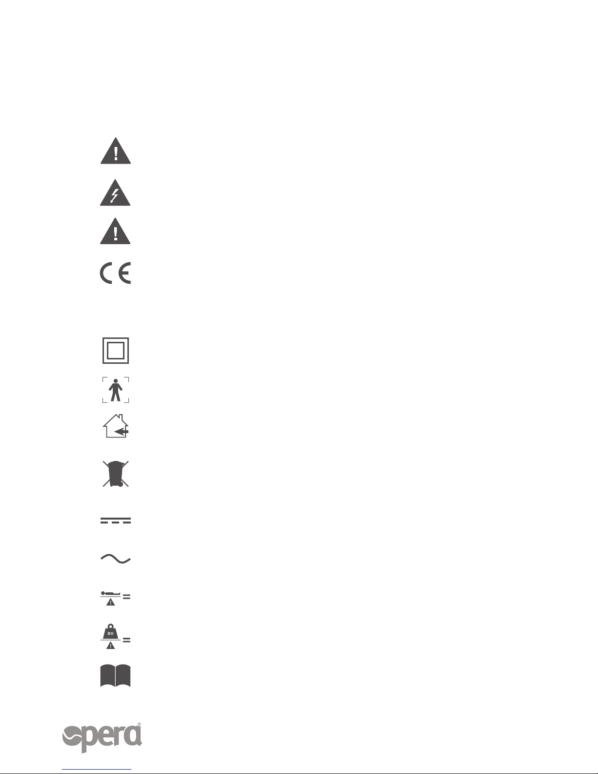
Read information with this symbol carefully and urgently follow instructions.
This information is safety-relevant.
This symbol indicates hazards due to electrical voltage. There is mortal danger!
This symbol indicates general hazards. There is danger to life and health.
Conformity mark in accordance with the Medical Device Directive (93/42 EEC).
The electrical equipment is splash-proof.
Symbol for Protection Class II device, double shock-proof.
Symbol for type B device according to DIN EN 60601-1.
This care bed may only be used indoors
This product must be disposed of in a separate refuse collection in the
European Union. Do not dispose of as normal domestic waste.
Symbol for direct current.
Symbol for alternating current.
Maximum permissible load.
Maximum patient weight.
Read instructions

3
Eco/Classic Installation Guide and Technical Specification
* These items are already fitted to the Head/Footboards
** These items are already fitted to the Mattress Platform Sections
Actual Size
2. Installation and Commissioning
OP011 Head/Footboard x 2 OP012 Side Rail x 4
What’s in the box:
OP043 Black Thumb Screws** x 4

4
Eco/Classic Installation Guide and Technical Specification
2. Installation and Commissioning
OP016 Transportation
Bracket x 2
OP014 Mattress Platform Backrest Section
N.B. Easily identifiable because it has both an actuator and
the black control box.
OP015 Mattress Platform Legrest Section
N.B. Easily identifiable because it only has one actuator.
OP017 Mattress Holding
Clip** x 4
OP018 Side Rail End
Cap x 8
OP019 Side Rail Runner* x 4
Before you begin, you will also need:
• Wall space with a plug socket nearby
• Tools: Phillips-head screwdriver; 6mm Allen Key; A pair of scissors
OP021 Power TransformerOP020 Handset

5
Eco/Classic Installation Guide and Technical Specification
Position the bed
Move the bed into the centre of the room and place
the side rail box to one side. Remove the cardboard
transportation cover.
1
Place accessories to one side
Detach the Side Rail End Caps
packet and place to one side.
2
OP018
2. Installation and Commissioning

6
Eco/Classic Installation Guide and Technical Specification
Detach transportation device
Wheel the bed parallel to a support, ideally the wall where
the bed will be finally positioned. Release the two securing
bolts on the transportation brackets. Then apply the brakes
on the castors of the head/footboard closest to the wall
(this is now the headboard).
Remove the mattress platform
Remove the mattress platform sections one at a time from
the transportation trolley by pulling them out of the holders
on the transportation brackets. Place them both to one
side, ensuring they are accessible for later steps.
3
4
2. Installation and Commissioning

7
Eco/Classic Installation Guide and Technical Specification
2. Installation and Commissioning
Check actuator pins
As part of commissioning the bed, it is
important to check the actuator pins on
the mattress platform sections are all
present and in the correct positions. Each
actuator should have two locking pins, one
at each end. Ensure each pin is in the locked
position. See below.
5
✔
✖✖

8
Eco/Classic Installation Guide and Technical Specification
Detach headboard
Remove the footboard from the transportation brackets,
leaning the headboard against the wall. Place the footboard
to one side. Then remove the transportation brackets
from the headboard and place the backrest section of the
mattress platform (OP014) in front of the headboard.
6
2. Installation and Commissioning

9
Eco/Classic Installation Guide and Technical Specification
Fit headboard to platform
Attach the backrest section of the mattress platform to the
headboard. Make sure the headboard is stood upright and
connect the backrest section by placing the steel prongs on
the platform into the grooves on the headboard. Secure in
place using the Mattress Platform Securing Bolt (pictured
below).
7
repeat
x2

10
Eco/Classic Installation Guide and Technical Specification
Connect platform sections
Connect the legrest section (OP015) to the backrest
section to complete the mattress platform. Slide the
steel side channel prongs on the backrest section into the
side channel openings on the legrest section. Ensure the
actuator on the legrest section is at the centre of the bed,
near to the control box. Pull the two sections together fully
and secure in place using the Black Thumb Screws.
8
repeat
x4

11
Eco/Classic Installation Guide and Technical Specification
Attach footboard
Attach the footboard to the end of the mattress platform
in the same way as the headboard was attached in step 6,
securing in place using the two black securing bolts.
9
Remove cable ties
Using scissors, remove the cable ties around the actuator
motors; handset control; and mattress platform, being
careful not to damage any wires. Do not remove the
cable ties found on the actuators inside the head and
footboards.
10
2. Installation and Commissioning

12
Eco/Classic Installation Guide and Technical Specification
Activate actuators
Lift the backrest profiling section fully, it should remain
upright without support. This will give you free access to
the control box. Remove the control box socket cover
using the Philips head screwdriver. Insert all four actuator
cables into the correct colour-coded sockets alongside the
handset cable and replace the cover.
11

13
Eco/Classic Installation Guide and Technical Specification
12
Fit side rail end caps
Unpack the side rails (OP012) from their box. Lay all four
side rails on the floor. Fit the plastic end caps (OP018) to
both ends of the rails. The easiest
way to put the end caps on is to
use the bottom of the side rail as a
leading edge (as pictured).
2. Installation and Commissioning
Fit side rails to headboard
At the head end of the bed, press the triangular latch to
release the side rail runner, bringing it down to its lowest
position. The steel fingers should now be at the bottom
of the channel. Fit the wooden side rails onto the side rail
runner by sliding the fingers all the way into the wood of
the side rails. The side rail runner fingers go into the top
and bottom holes of the side rail.
13

14
Eco/Classic Installation Guide and Technical Specification
2. Installation and Commissioning
Complete side rail fitting
At the footend of the bed, release the black securing bolts
and pull the footboard away from the mattress platform.
This will allow enough room to fit the wooden side rails
onto the side rail runner. Slide the fingers all the way into
the wood of the side rails. Reconnect the footboard to the
mattress platform and reconnect the black securing bolts.
14
ab
c
d
repeat

15
Eco/Classic Installation Guide and Technical Specification
Mattress holders
Clip in place the mattress holders (OP017), 2 slats
down from the top of the
backrest, and 2 slats up
from the bottom of the
legrest. Repeat for the
other side of the bed.
15
Test functions
Connect the bed to mains power. Test the controls
on the bed are working correctly, by performing the
following steps:
I. Test the height adjustment
II. Test the trendelenburg feature
III. Test the anti-trendelenburg feature
IV. Lower the bed into the lowest position
V. Test the backrest elevation
VI. Test the legrest elevation
16
2. Installation and Commissioning

16
Eco/Classic Installation Guide and Technical Specification
2. Installation and Commissioning
Confirm compliance
Measure the distance between the mattress top and the
side rails when in the up position. This distance should be
around 110mm, which is less than the maximum 120mm
stipulated in the bed rail regulations.
17
Position the bed
Once the testing has been completed satisfactorily, you are
ready to move the bed into the desired position. Turn the
castors into the bed, and apply the brakes. You are now
ready to place the mattress onto the bed.
18

17
Eco/Classic Installation Guide and Technical Specification
Installation Complete!
Remove all packaging and the transportation brackets
from the room, and you have successfully completed the
installation!
19
2. Installation and Commissioning

18
Eco/Classic Installation Guide and Technical Specification
2. Installation and Commissioning

19
Eco/Classic Installation Guide and Technical Specification
2. Installation and Commissioning
Construct the Patient Pole
Assemble the patient pole by first fitting together
the two poles by inserting the smaller end of the
crooked pole into the opening in the straight pole.
Secure by tightening the black thumb screw,
ensuring it threads through both the hole in the
straight pole and the hole in the crooked pole.
1
Secure Patient Pole to the Bed
Insert the patient pole into the holding sleeve in the
corner of the mattress platform. Slot the pole in
fully, ensuring the cylinder pins are in the notches at
the top of the sleeve.
2
This manual suits for next models
3
Table of contents
Popular Medical Equipment manuals by other brands

Limbs & Things
Limbs & Things ECOSystem 80197 user guide

Joerns
Joerns CairTurn RT User & service manual

Medline
Medline AEROMIST COMPACT HCS70004RD instruction manual

EMD Serono
EMD Serono RebiSmart 3.0 Instructions for use

ENOCHS
ENOCHS Regency Series Installation & operation manual

Joerns
Joerns Oxford 0Y0050 User instruction manual