FTRCUd-210.021
Stand 11.2018 (11/081) 1 5 21 864 01
Bedienungsanleitung
b@home-Bedienteil
Sicherheitshinweis
Dieses Gerät darf nur durch eine Elektrofachkraft geöffnet und gemäß
dem entsprechenden Schaltbild auf dem Gehäuse oder in der Bedie-
nungsanleitung installiert werden. Dabei sind die bestehenden Sicher-
heitsvorschriften zu beachten.
Safety note
Expert electricians only may open this device in due compliance with the
wiring diagram shown on the housing / represented in the corresponding
operating instructions. All expert electricians charged with the execution
of such works must comply with the relevant safety regulations currently
operative and in force.
Operating instructions
b@home control panel
Achtung! Der Betrieb in der Nähe von Geräten, welche nicht den
EMV-Bestimmungen entsprechen, kann zur Beeinflussung der
Gerätefunktionen führen. Nach der Installation ist der Betreiber,
durch die ausführende Installationsfirma, in die Funktion und Bedienung
der Regelung einzuweisen. Die Bedienungsanleitung muss für Bedien-
und Wartungspersonal an frei zugänglicher Stelle aufbewahrt werden.
Caution! The operation of the controller in the vicinity of other
devices that do not comply with the EMC directives may affect its
functions. The company charged with the installation of the device
must, after the completion of the installation works, instruct the user of the
control system into its functions and in how to operate it correctly. These
operating instructions must be kept at a place that can be accessed freely
by the operating and/or servicing personnel in charge.
Inhaltverzeichnis Table of contents, overview
1. Hinweise zur Bedienung .................................................................... 1
2. Anwendung als zentrales Bedienteil / Raumbedienteil........................1
3. Verbinden mit dem b@home-Gate.....................................................2
4. Betrieb am b@home-Gate .................................................................2
4.1 Temporäre Solltemperatureinstellung (nur bei Raumbedienteil verfüg-
bar)........................................................................................................2
4.2 Auswahl der Betriebsart / Frostschutz (nur bei Raumbedienteil ver-
fügbar)...................................................................................................2
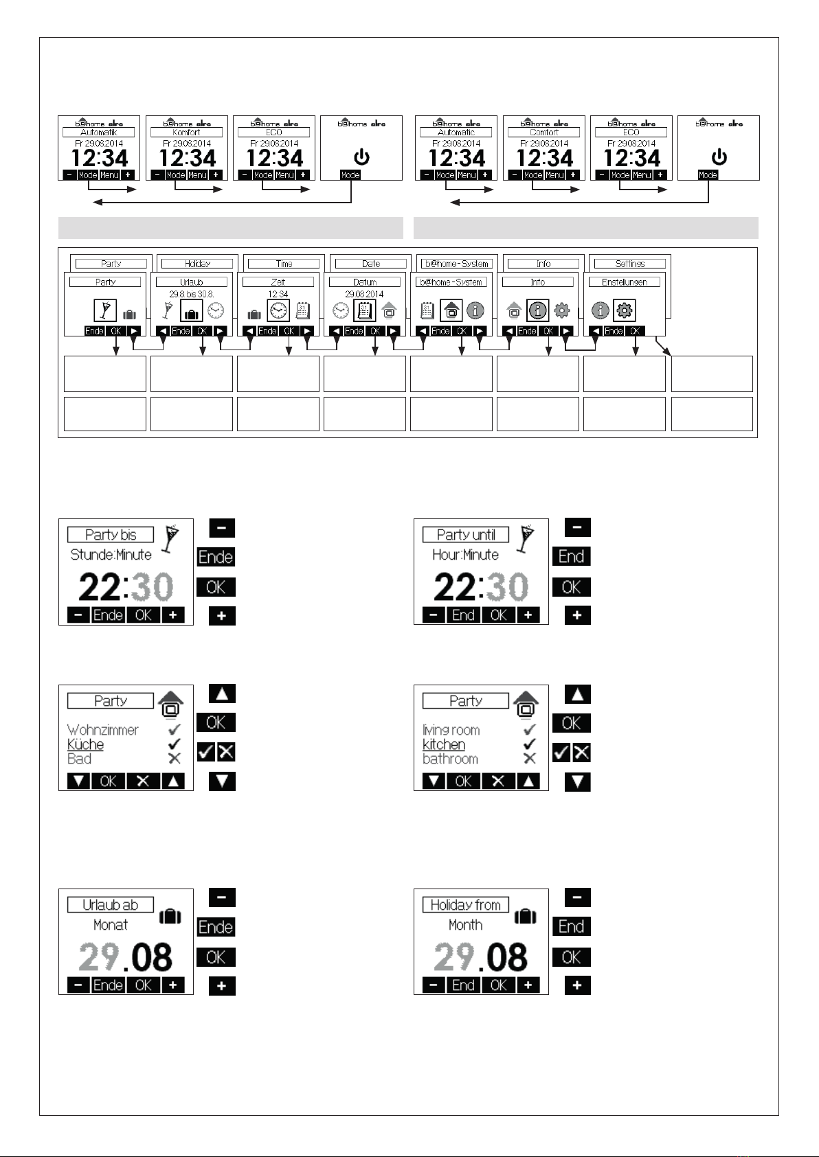
5. Hauptmenü........................................................................................3
5.1 Untermenü Party .............................................................................3
5.2 Untermenü Urlaub ........................................................................... 3
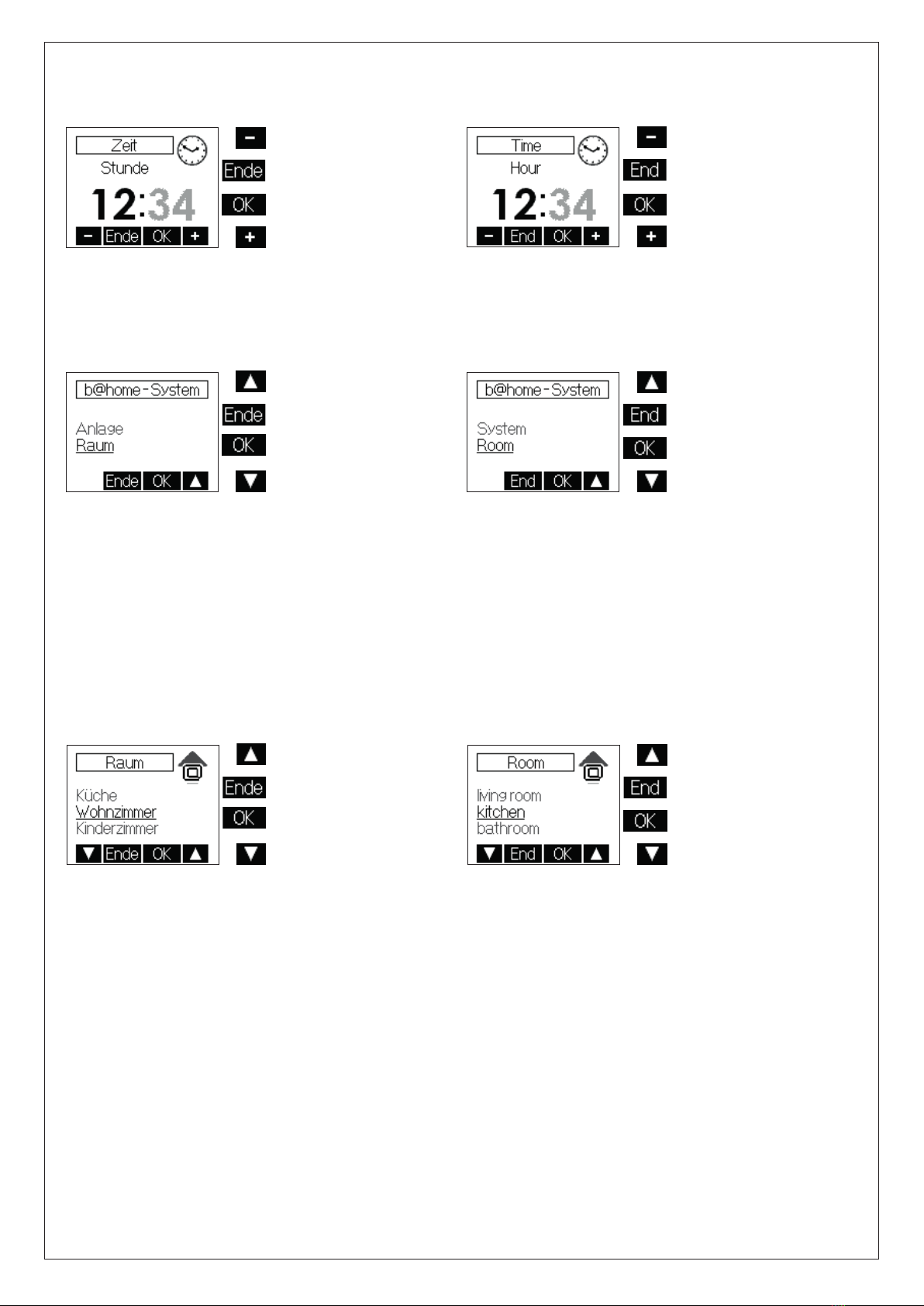
5.3 Einstellen der Uhrzeit / des Datums .................................................4
5.4 Untermenü b@home-System...........................................................4
5.4.1 Anlageneinstellungen....................................................................4
5.4.2 Raumeinstellungen .......................................................................4
5.4.2.1 Einstellung der Solltemperaturen................................................5
5.4.2.2 Eingabe der Tagesprogramme...................................................5
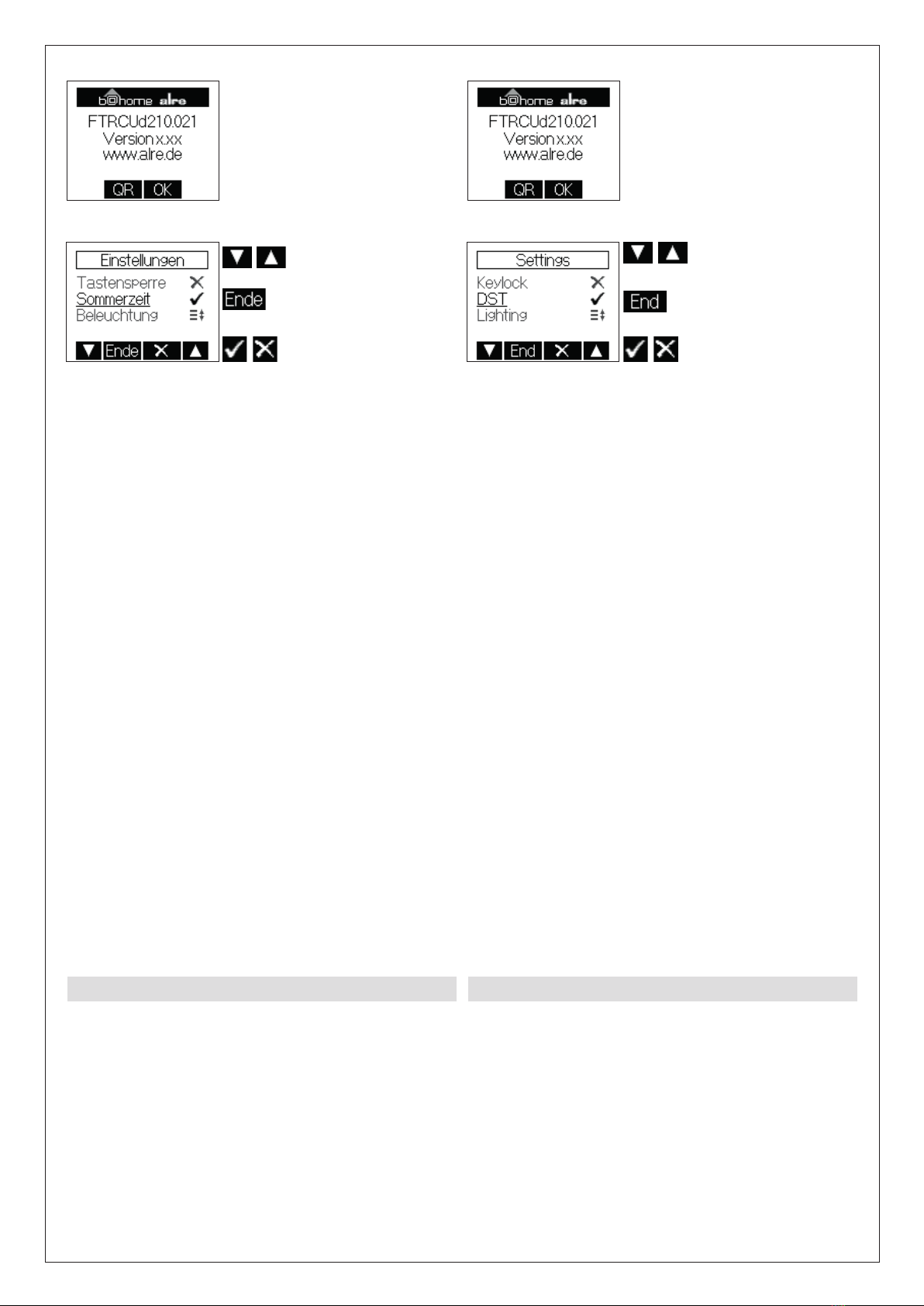
5.5 Information ......................................................................................6
5.6 Einstellungen ...................................................................................6
6. Expertenmenü ...................................................................................6
7. Montage / Anschluss .........................................................................8
8. Erstinbetriebnahme ............................................................................8
9. Anschluss- und Maßzeichnung..........................................................8
10. Technische Daten.............................................................................9
11. Zubehör ...........................................................................................9
12. Sensorkennlinie................................................................................9
13. Gewährleistung ................................................................................9
1. Operating instructions.......................................................................1
2.
Application as central control unit / unit for the control of individual rooms
..1
3. Connecting to the b@home-Gate .....................................................2
4. Use with the b@home gate...............................................................2
4.1 Temporary set temperature settings (available only if using the unit
for the control of individual rooms) ........................................................2
4.2 Selection of the operating mode / frost protection (available only if
using the unit for the control of individual rooms) ..................................2
5. Main menu .......................................................................................3
5.1 Submenu „Party“............................................................................3
5.2 Submenu „Holiday“ ........................................................................3
5.3 Setting of the time / date ................................................................4
5.4 Submenu b@home system.............................................................4
5.4.1 System settings...........................................................................4
5.4.2 Entry of settings for the control of individual rooms ......................4
5.4.2.1 Entry of the set temperatures....................................................5
5.4.2.2 Entry of the weekday programs ................................................5
5.5 Information .....................................................................................6
5.6 Settings..........................................................................................6
6. Expert menu.....................................................................................6
7. Mounting / connection......................................................................8
8. Initial start-up ....................................................................................8
9. Wiring diagram and dimensioned drawing.........................................8
10. Technical data ................................................................................9
11. Accessories ....................................................................................9
12. Sensor characteristic curve.............................................................9
13. Warranty .........................................................................................9
1. Hinweise zur Bedienung 1. Operating instructions
Das Bedienteil besitzt 4 Sensortastflächen, die durch die geprägten Ovale
gekennzeichnet sind. Ihre Funktion kann sich abhängig von der Bedie-
nung verändern und wird jeweils im Display oberhalb der Ovale angezeigt.
Das Bedienteil verfügt über eine Schutzfunktion, die ein unbeabsichtigtes
Betätigen der Tastflächen verhindert. Die Funktion wird 20 Sekunden nach
der letzten Berührung einer Tastfläche aktiv und wird durch Berühren einer
beliebigen Tastfläche für ca. 2 Sekunden wieder deaktiviert (siehe Hinweis
im Display). Die Verfügbarkeit bestimmter Menü- und Einstellfunktionen
ist von der Konfiguration des b@home-Gates abhängig. Mit Ausnahme
der temporären Solltemperatureinstellung werden alle Menü- und Einstell-
funktionen zwei Minuten nach der letzten Betätigung einer aktiven Tast-
fläche selbsttätig beendet. Noch nicht bestätigte Eingaben werden dabei
verworfen. Im genutzten Frequenzbereich beträgt die maximale erlaubte
Sendezeit eines jeden Gerätes 1 % pro Stunde (36 Sekunden). Nach Er-
reichen des 1 %- Limits darf das Gerät nicht mehr senden. Im normalen
Betrieb wird der Duty Cycle in der Regel nicht vollständig ausgenutzt. In
Einzelfall, speziell bei der Erstinstallation des Gerätes, kann durch ver-
mehrtes Senden das Limit erreicht werden. Dann stellt das Bedienteil die
Sendungen ein und zeigt einen Hinweis im Display an. Nach kurzer Zeit
(max. 1 Stunde) ist die Funktion des Gerätes wiederhergestellt.
The device is equipped with 4 touch keys, all of which have been mar-
ked by imprinted ovals. The functions allocated to them may vary in de-
pendence on the operation requirements. The related function is being
indicated on the display that exists above the corresponding keys. A spe-
cial protective function helps prevent an inadvertent activation of the touch
keys. This function is activated 20 seconds after any of the touch keys has
last been activated. Actuating any of these keys deactivates this function
again for 2 seconds (see advice indicated on the display). The availabi-
lity of certain menu and/or setting functions depends on the configura-
tion of the b@home-Gate. Except for the temporary target temperature
setting, all menu and configuration settings are automatically cancelled
two minutes after an active button was last pressed. Any entries not yet
confirmed will be discarded. In the frequency range used the maximum
transmission time for each device is 1 % per hour (36 seconds). Once the
1 % limit has been reached the device may no longer transmit. During
normal operation the duty cycle is typically not fully utilised. In some cases,
specifically when first installing the device, the limit can be reached due to
increased transmission. The control panel will then stop transmitting and
a message will appear in the display. After a short time (max. 1 hour) the
device will be functional again.
2. Anwendung als zentrales Bedienteil /
Raumbedienteil
2. Application as central control unit / unit for
the control of individual rooms
Dieses Funk-Bedienteil wurde speziell für das b@home-Gate entwickelt.
Es kann als zentrales Bedienteil oder als Raumbedienteil mit dem b@
home-Gate verbunden werden.
- Als zentrales Bedienteil stellt es einen Eingang zur zentralen Beeinflus-
sung des b@home-Gates zur Verfügung. Dieser kann, je nach Einstel-
lung, als potentialfreier Kontakteingang „ECO“, „Standby“ (Frostschutz),
„Heiz-/Kühlumschaltung“ oder als Sensoreingang „Vorlauffühler“ oder
This control unit has been specially devised for use in combination with
the b@home-Gate. It can be connected to the b@home-Gate and used
for either central control or the control of individual rooms.
- When used for central control tasks, the device provides one input that
allows to remote-control the b@home-Gate centrally from one spot. This
input can, depending on the setting, be used as a potential-free „ECO“ or
„standby“ (frost protection), heating/cooling switch-over or sensor input