Airmax 653945 User manual

Table of Contents:
INSTALLATION INSTRUCTIONS
Item #653945 - 2 HP 460v
#653946 - 3 HP 460v
#653947 - 5 HP 460v
460v Three Phase
Control Panels
Important Information ................... 2
2 - 5 HP 460v Contents & Installation ..... 3-6
2 - 5 HP 460v Wiring Diagrams ............7-9
Timer Maintenance & Operation ........10 -11
Warranty Information ....................12

ENGLISH
airmaxeco.com | 866-424-7629
2
IMPORTANT INFORMATION:
Please read these instructions thoroughly before use. Failure to follow
instructions may result in equipment damage or failure, losses, injury or death.
Electrical connections to the control panel and proper grounding (properly sized
copper conductor from the grounding terminal to the service panel or grounding
rod) are to be completed by a licensed electrician and in accordance with the National
Electric Code, local codes or ordinances.
WARNING:
To reduce the risk of electric shock or injury:
• Install only on a circuit protected by a Ground Fault Circuit Interrupter (GFCI). ALWAYS
install an acceptable safety shut-o switch between the main power source and
control panel.
• DO NOT operate the control panel if electrical cords are broken or spliced.
• ALWAYS turn o electrical power before installing, removing or servicing the control
panel components.
• DO NOT immerse the control panel in water.
• This control panel is NOT intended for use in swimming areas, or other situations
where bodily contact is made with the water. Although the control panel is designed
for outdoor use, it should never be submerged in water.
CAUTION:
To reduce the risk of equipment damage or failure:
• The control panel is NOT submersible; do not place the timer where it might contact
or fall into the water.
• DO NOT operate the control panel with a unit that exceeds the maximum voltage
indicated by the control panel specications. Operating with a unit larger than
recommended can cause damage to the control panel and will NOT be covered
under warranty.
IMPORTANT: Airmax is not responsible for equipment damage or failure, losses,
injury or death resulting from failure to follow safety precautions, misuse or
abuse of equipment.
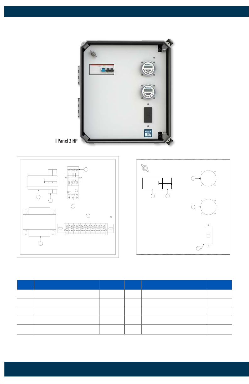
TECHNICAL SPECIFICATIONS:
ITEM NUMBER VOLTAGE PANEL DIMENSIONS MOUNTING DIMENSIONS
653945 2 HP 460v 16”w x 17 ¾”h x 8 ½”d 12”w x 18 ½”h
653946 3 HP 460v 16”w x 17 ¾”h x 8 ½”d 12”w x 18 ½”h
653947 5 HP 460v 16”w x 17 ¾”h x 8 ½”d 12”w x 18 ½”h

ENGLISH
contactus@airmaxeco.com 3
Airmax 460v Control Panel 2 HP
2 HP 460v REPLACEMENT PARTS:
ITEM DESCRIPTION PART # ITEM DESCRIPTION PART #
1 Motor GFCI Breaker (25 Amp) 652207 6 Screw Clamp Feed-Through Kit 651781
2 Control Breaker (3 Amp) 652208 7 Motor Timer 651112
3 Transformer 652209 8 Light Timer 651112
4 2 - 5 HP Contactor 651962 9 Light GFCI 651952
5 2 HP Overload Relay 652205
2 HP 460v PRODUCT CONTENTS:
1
2
3
5
6
4
Airmax
TIMER
Airmax
TIMER
7
8
9
Item
Description
1
Transformer
Control Breaker (3 Amp)
Motor GFCI Breaker (25 Amp)
Motor Starter
Motor Starter Overload
2
3
4
5
6
6
Part Number
652207
652208
652209
651962
652205
Item
Description
Part Number
Terminal Blocks (Gray)
Motor Timer
Light Timer
Light GFCI
7
8
651940
651112
651112
2
1
2 HP 480 Volt
Airmax 2 HP 480V Component Location
Terminal Blocks (Green)
652125
9 651952

ENGLISH
airmaxeco.com | 866-424-7629
4
3 HP 460v PRODUCT CONTENTS:
Airmax 460v Control Panel 3 HP
1
2
3
5
6
4
Airmax
TIMER
Airmax
TIMER
7
8
9
Item
Description
1
Transformer
Control Breaker (3 Amp)
Motor GFCI Breaker (25 Amp)
Motor Starter
Motor Starter Overload
2
3
4
5
6
6
Part Number
652207
652208
652209
651962
652206
Item
Description
Part Number
Terminal Blocks (Gray)
Motor Timer
Light Timer
Light GFCI
7
8
651940
651112
651112
2
1
3 HP 480 Volt
Airmax 3 HP 480V Component Location
Terminal Blocks (Green)
652125
9 651952
3 HP 460v REPLACEMENT PARTS:
ITEM DESCRIPTION PART # ITEM DESCRIPTION PART #
1 Motor GFCI Breaker (25 Amp) 652207 6 Screw Clamp Feed-Through Kit 651781
2 Control Breaker (3 Amp) 652208 7 Motor Timer 651112
3 Transformer 652209 8 Light Timer 651112
4 2 - 5 HP Contactor 651962 9 Light GFCI 651952
5 3 HP Overload Relay 652206

ENGLISH
contactus@airmaxeco.com 5
5 HP 460v PRODUCT CONTENTS:
Airmax 460v Control Panel 5 HP
1
2
3
5
6
4
Airmax
TIMER
Airmax
TIMER
7
8
9
Item
Description
1
Transformer
Control Breaker (3 Amp)
Motor GFCI Breaker (25 Amp)
Motor Starter
Motor Starter Overload
2
3
4
5
6
6
Part Number
652207
652208
652209
651962
651883
Item
Description
Part Number
Terminal Blocks (Gray)
Motor Timer
Light Timer
Light GFCI
7
8
651940
651112
651112
2
1
5 HP 480 Volt
Airmax 5 HP 480V Component Location
Terminal Blocks (Green)
652125
9 651952
5 HP 460v REPLACEMENT PARTS:
ITEM DESCRIPTION PART # ITEM DESCRIPTION PART #
1 Motor GFCI Breaker (25 Amp) 652207 6 Screw Clamp Feed-Through Kit 651781
2 Control Breaker (3 Amp) 652208 7 Motor Timer 651112
3 Transformer 652209 8 Light Timer 651112
4 2 - 5 HP Contactor 651962 9 Light GFCI 651952
5 5 HP Overload Relay 651883

ENGLISH
airmaxeco.com | 866-424-7629
6
2 HP, 3 HP & 5 HP 460v
INSTALLATION INSTRUCTIONS:
Airmax Control Panels are designed for outdoor use but should be mounted above any
high water levels. Holes should be drilled into the bottom of the control panel for electrical
access. We recommend using grommets to protect and seal the electrical access points and
to help keep the control panel clean.
It is recommended that you have between 460 and 495 combined volts on any two of
your incoming terminals (L1-L2, L1-L3, or L2-L3). Excessively high or excessively low
voltage could cause potential harm to the control panel or motor components.
CONNECTING ELECTRICAL WIRING:
CONNECT UNIT TO CONTROL PANEL
WARNING:
Turn o electrical power before connecting units to the control panel.
Connect to a Fountain:
• Black lead to T1 on the terminal strip
• White lead to T2 on the terminal strip
• Red lead to T3 on the terminal strip
• Green lead to the grounding terminal
Connect to Fountain Lights (optional):
• Black lead to LT1 on the terminal strip
• White lead to LT2 on the terminal strip
• Green lead to the grounding terminal
CONNECT CONTROL PANEL TO POWER SOURCE
Connect the following:
• Line 1 to L1 on the terminal strip
• Line 2 to L2 on the terminal strip
• Line 3 to L3 on the terminal strip
• Green lead to the grounding terminal
• Set or verify that the overload assembly in the control panel is set to the
motor nameplate value.
• If the fountain does not produce a pattern or if amp draw is excessive, it may
be necessary to recongure the orientation of the incoming leads on L1,
L2 & L3. Please reach out to Airmax Technical Support for troubleshooting
assistance.
L2 L3 GND T2 T3 GND GNDLT 1 LT 2
LIGHTS X
FOUNTAIN
POWER
T1L1

ENGLISH
contactus@airmaxeco.com 7
2
51
4
L1
L2
L3
MOTOR TIMER
1L1
3L2
5L3
2T1
4T2
6T3
96
95
TO FOUNTAIN
T1 T2 T3 GND
HOT NEUTRAL
TO LIGHTS
A1
A2
2
51
4
LIGHT TIMER
GFCI
LED
LIGHTS
460V
25A FLA
MIN SERVICE
25A
MIN 12AWG
COPPER
60°C
460V
3.4 RLA
MIN 12AWG
COPPER
60°C
115V
3 RLA
MIN 16AWG
COPPER
60°C
460/230VAC
to 115VAC
TRANSFORMER
GFEP 30mA
25A MOTOR
BREAKER
3A CONTROL
BREAKER
2.8 - 4.0A
OVERLOAD
2HP - 3 Phase 460V
GND
CONTACTOR
L1
L2
L3
H1 H4
T1 T2 T3
1L1
3L2
5L3
2
LT1 LT2
X2
N
3
4
1
1
N
N
GND
GND
2 HP 460v CONTROL PANEL WIRING DIAGRAM:
• Main Disconnect Supplied and Installed by Licensed Electrician
• Input Hubs Must Comply With UL 514B
*Shall Be Provided By Installer

ENGLISH
airmaxeco.com | 866-424-7629
8
3 HP 460v CONTROL PANEL WIRING DIAGRAM:
• Main Disconnect Supplied and Installed by Licensed Electrician
• Input Hubs Must Comply With UL 514B
*Shall Be Provided By Installer
2
51
4
L1
L2
L3
MOTOR TIMER
1L1
3L2
5L3
2T1
4T2
6T3
96
95
TO FOUNTAIN
T1 T2 T3 GND
HOT NEUTRAL
TO LIGHTS
A1
A2
2
51
4
LIGHT TIMER
GFCI
LED
LIGHTS
460V
25A FLA
MIN SERVICE
25A
MIN 12AWG
COPPER
60°C
460V
4.8 RLA
MIN 12AWG
COPPER
60°C
115V
3 RLA
MIN 16AWG
COPPER
60°C
460/230VAC
to 115VAC
TRANSFORMER
GFEP 30mA
25A MOTOR
BREAKER
3A CONTROL
BREAKER
4.0 - 6.3A
OVERLOAD
3HP - 3 Phase 460V
GND
CONTACTOR
L1
L2
L3
H1 H4
T1 T2 T3
1L1
3L2
5L3
2
LT1 LT2
X2
N
3
4
1
1
N
N
GND
GND

ENGLISH
contactus@airmaxeco.com 9
5 HP 460v CONTROL PANEL WIRING DIAGRAM:
• Main Disconnect Supplied and Installed by Licensed Electrician
• Input Hubs Must Comply With UL 514B
*Shall Be Provided By Installer
2
51
4
L1
L2
L3
MOTOR TIMER
1L1
3L2
5L3
2T1
4T2
6T3
96
95
TO FOUNTAIN
T1 T2 T3 GND
HOT NEUTRAL
TO LIGHTS
A1
A2
2
51
4
LIGHT TIMER
GFCI
LED
LIGHTS
460V
25A FLA
MIN SERVICE
25A
MIN 12AWG
COPPER
60°C
460V
8.0 RLA
MIN 12AWG
COPPER
60°C
115V
3 RLA
MIN 16AWG
COPPER
60°C
460/230VAC
to 115VAC
TRANSFORMER
GFEP 30mA
25A MOTOR
BREAKER
3A CONTROL
BREAKER
7.0 - 10.0A
OVERLOAD
5HP - 3 Phase 460V
GND
CONTACTOR
L1
L2
L3
H1 H4
T1 T2 T3
1L1
3L2
5L3
2
LT1 LT2
X2
N
3
4
1
1
N
N
GND
GND

ENGLISH
airmaxeco.com | 866-424-7629
10
Maintenance & Operation
of the Control Panel Timer:
RUN TIME USING THE MANUAL BYPASS
Press the MANUAL button until the line is above“ON”. This mode will bypass all
programmed settings. The MANUAL/ON mode can be used if 24/7 operation is desired.
RUN TIME USING A PROGRAM
Setting the Clock
Step 1: Press the RESET button to clear all history from
memory.
Step 2: Press and hold the CLOCK button.
Step 3: Continue to hold the CLOCK button while
pressing the DAY, HOUR or MIN button to set
the day and time.
Step 4: Release the CLOCK button.
CREATING A PROGRAM
The Airmax Digital Timer allows up to 8 ON/OFF run times.
Select the days for each run time to occur based on the 15 preset schedule of days
shown in the table. (Fig. 1 - Page 11)
Note: Ponds will receive the most benet from continual water movement. We
recommend running fountains at least 8-10 hours daily to maximize benets, unless a
secondary aeration system is in operation.
Step 1: Press the TIMER button once to display ”1on --:--“
Step 2: Press the DAY button to scroll through the preset schedule options. Mode A,
MONDAY - SUNDAY, is the default schedule.
Step 3: When the desired schedule is displayed, press the HOUR or MIN buttons to
select the ON time.
Step 4: Press the TIMER button once to switch display to“1o --:--“ Programming
without inserting an OFF time will also allow the fountain to run 24/7 if
desired.
Step 5: Press the DAY button to scroll to the program selected in step 2.
Step 6: Press the HOUR or MIN button to select the OFF time.
Step 7: Repeat steps 1-6 for each additional program desired, up to 8 programs.
Step 8: When all programs have been created press the CLOCK button to execute the
programs.
Step 9: Press the MANUAL button until the line is above AUTO.
Reset Button

ENGLISH
contactus@airmaxeco.com 11
Maintenance & Operation
of the Control Panel Timer Cont.:
EDITING A PROGRAM
Review a Program – To review the list of current programs, press the TIMER button
repeatedly to scroll through the programs. When nished press the CLOCK button
to return to the time of day.
Change an On/O Time – To adjust an On/O time, press the TIMER button to scroll
to the program you want to change. Press the DAY, HOUR or MIN buttons to adjust
the time. When nished press the CLOCK button to return to the time of day.
Add a Program – If there are not already 8 programs running, you may elect to add
an additional program by following the CREATING A PROGRAM procedure.
Remove a Program – In the event that a program needs to be removed, you will
need to RESET the timer and program only the desired schedules.
REPLACING THE BATTERY
Note: Timer settings will be retained for
approximately 1 minute once the battery is
removed. Each timer uses (1) CR2032 Lithium
Battery.
Step 1: On the back of the timer, use a small
athead screwdriver or similar to pull the battery
compartment from the timer.
Step 2: Install a new battery (print side down)
and reinstall the battery compartment.
Gently Pull Here
a. MO TU WE TH FR SA SU
b. MO
c. TU
d. WE
e. TH
f. FR
g. SA
h. SU
i. MO TU WE TH FR
j. SA SU
k. MO TU WE TH FR SA
l. MO TU WE
m. TH FR SA
n. MO WE FR
o. TU TH SA Fig. 1
DAYS FOUNTAIN IS RUNNING
PRESET MODES

ENGLISH
airmaxeco.com | 866-424-7629
12
WARRANTY:
Airmax Control Panels are covered under the system warranty
(3 Years - EcoSeries & PondSeries / 5 Years - LakeSeries)
#653899 V1
THANK YOU FOR CHOOSING:
Airmax, Inc.
15425 Chets Way Street, Armada, MI 48005
866-424-7629 | www.airmaxeco.com | contactus@airmaxeco.com
This manual suits for next models
2
Table of contents
Other Airmax Control Panel manuals
Popular Control Panel manuals by other brands

elsner elektronik
elsner elektronik KNX WS1000 Color Brief Instruction

MCM Electronics
MCM Electronics iRIS 8 user guide

EL.MO. Spa
EL.MO. Spa TA1002 user manual

Carrier
Carrier Touch Pilot 30XW-V manual

NTEK Systems
NTEK Systems DoorPad quick start guide

Teletek electronics
Teletek electronics REPEATER Installation and programming manual

Crystal Vision
Crystal Vision SW808 Controller-48V user manual

CAME
CAME TS07 Installation and setting manual

ELCOS
ELCOS CEM-380 Instruction and user's manual

Allen-Bradley
Allen-Bradley 2707-M232P3 user manual

jablotron
jablotron JA-80K Oasis installation instructions

Chamberlain
Chamberlain LiftMaster 398LM Owner's instructions